
TSB Laboratory Report LP181/2013
Table of contents
1.0 Introduction
1.1 Description of occurrence
1.1.1
On 05 July 2013, at about 2250 Eastern Daylight Time, Montreal, Maine & Atlantic Railway (MMA) freight train MMA-002 (the train), en route from Montréal, Quebec, to Saint John, New Brunswick, was stopped at Nantes, Quebec (Mile 7.40 of the Sherbrooke Subdivision), the designated MMA crew change point. At about 2350, a local resident reported a fire on the lead locomotive (MMA 5017) to the 911 emergency call centre. Subsequently the local fire department responded along with another MMA employee. Emergency shutdown procedures were initiated on the lead locomotive, and the fire was extinguished. The train, consisting of 5 head-end locomotives, 1 VB car (special purpose caboose), 1 box car, and 72 Class 111 tank cars carrying flammable liquids (petroleum crude oil, UN 1267, Class 3), was then secured on the main track on a descending grade.
1.1.2
Shortly before 0100 on 06 July 2013, the train started to move and gathered speed as it rolled uncontrolled down the descending grade into the town of Lac-Mégantic, Quebec, 7.4 miles southeast of Nantes. While travelling well in excess of the authorized speed, the train derailed near the centre of Lac-Mégantic. Numerous tank cars ruptured, and a fire ensued.
1.2 Engineering services requested
1.2.1
The Transportation Safety Board of Canada (TSB) Eastern Regional Operations – Rail/Pipeline requested that the TSB Engineering Laboratory conduct an examination of the lead locomotive’s engine to determine the cause of the engine fire.
1.3 Background
1.3.1
Lead locomotive MMA 5017 was a General Electric C30-7 built in 1979. Equipped with a 16-cylinder turbo-charged four-stroke diesel engine, the C30-7 creates 3000 horsepower and has two three-axle, three-motor trucks. This variant carries 4000 gallons of fuel, 365 gallons of coolant and 380 gallons of engine (lube) oil. The overall weight of MMA 5017 was approximately 195 tons.
2.0 Examination and analysis
2.1 Field examination
2.1.1
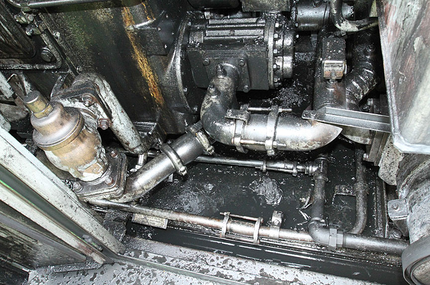
Initial field examination of the engine bay of MMA 5017 showed that engine oil had been dispersed inside the engine covers as well as outside, primarily near the turbocharger end of the engine. It could not be determined how much engine oil had been present in the engine bay prior to the fire, nor the extent to which this oil was disturbed in the act of extinguishing the fire. However, a significant amount of engine oil was observed all around the forward end of the engine (Figure 1).
2.1.2
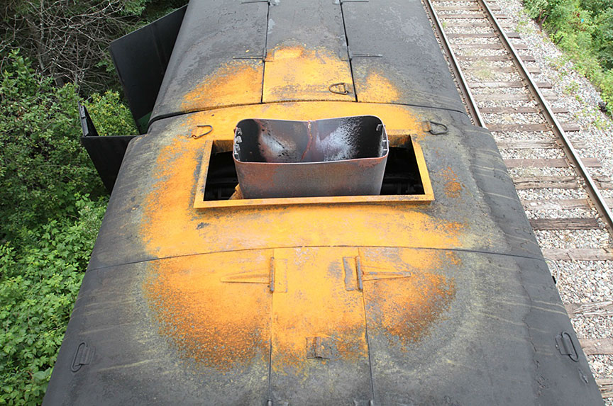
Examination of the exhaust stack and surrounding roof panels showed that the fire had been concentrated in that area (Figure 2). Fresh rust was visible where paint had been burned off portions of the roof immediately adjacent to the exhaust stack, and the stack itself was cracked. Visual inspection inside the exhaust stack indicated that the body of the turbocharger was approximately half full of a mixture of oil and water (Figure 3).

2.1.3
Removal of the valve covers revealed that the top of the number five power assembly on the right hand side (PA R5) was dry and coked, indicating that the valve train had been starved of oil for an extended period of time (Figure 4). The other power assemblies had a normal oily appearance (a representative example is shown in Figure 5 for comparison).


2.1.4
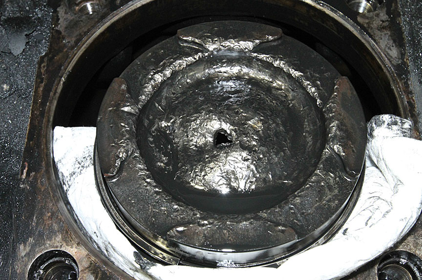
Removal of the crankcase inspection cover for PA R5 showed that the camshaft bearing between PA R4 and PA R5 was broken (Figure 6). A large section of the camshaft bearing had separated exposing the camshaft journal.

2.2 Visual examination of the engine
2.2.1
To facilitate further engine examination and a partial engine teardown, the locomotive consist was moved from Lac-Mégantic, Quebec to a maintenance facility in Saint John, New Brunswick. MMA 5017 was moved indoors and prepared for teardown. Removal of the exhaust stack allowed suction draining of the turbocharger body which contained approximately 10 liters of engine oil and 10 liters of water. The water was considered to have entered the turbocharger body as a result of firefighting operations.
2.2.2
The turbocharger exhibited missing and broken blades but could be rotated by hand, indicating that the turbo shaft bearings were in good condition (Figure 7). Rags were passed through the lower portion of the turbocharger body to look for turbine blade fragments. None were recovered.

2.2.3
After removal of the engine bay doors, the joining tube sections of the intake and exhaust manifolds were labelled and removed. Examination of the intake manifold tube and body sections showed a gradual increase in the buildup of engine oil from the front to the rear cylinders, with a more pronounced deposit on right side cylinders (Figure 8) than on left side cylinders (Figure 9). The exhaust manifold tube and body sections showed an increase in oil buildup from the rear to the front cylinders, with a greater buildup on the right side cylinders (Figures 10 and 11). This is consistent with the direction of normal air flow through the engine. A separated valve head was observed in the transition section just upstream of the turbine (Figure 12).


2.2.4
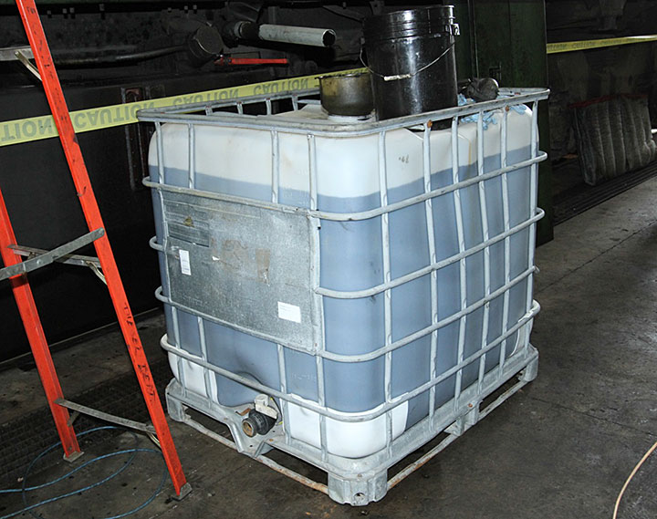
The engine oil was drained into a large plastic container to estimate the volume of oil remaining in the sump (Figure 13). Approximately 250 gallons of oil were recovered. The normal full sump volume was 380 gallons, indicating the level of engine oil was down approximately 130 gallons.
2.2.5
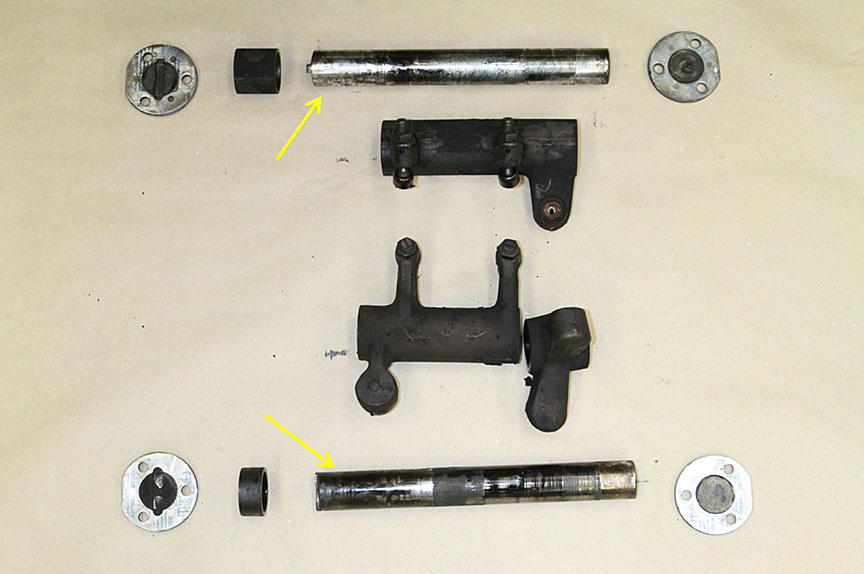
Examination of the camshaft section for PA R5 showed wear on the exhaust lobe and on the corresponding crosshead roller (Figure 14). The intake and fuel injector lobes and crosshead rollers had a normal appearance. Removal of the exhaust crossover pushrod from PA R5 showed that it was dry with fretting damage (Figures 15 and 16).


2.3 Engine teardown
2.3.1
Removal of the intake manifold body from PA R5 showed that the intake valve stems were present but bent (Figures 17 and 18). Removal of PA R5 revealed extensive damage to the piston crown, consistent with repeated interaction with the valves (Figure 19). A valve stem sized hole had been punched through the center of the piston crown and the edges of the dished portion showed batter. The remainder of the piston was unremarkable. The intake pushrod had bent (Figure 20). The combustion chamber for PA R5 was damaged (Figure 21). Both exhaust valve heads were separated from their stems; one head was found jammed in the exhaust port (Figure 22). Both intake valves were impact damaged such that they no longer seated properly. Although the rockers moved easily, removal of the rocker shafts from the PA required the use of a hammer and brass drift, consistent with partial seizure. The shafts and bearings were dry on either end where they mated with the PA. The center portions of the shaft had a paste-like coating of oil residue (Figure 23).


2.3.2
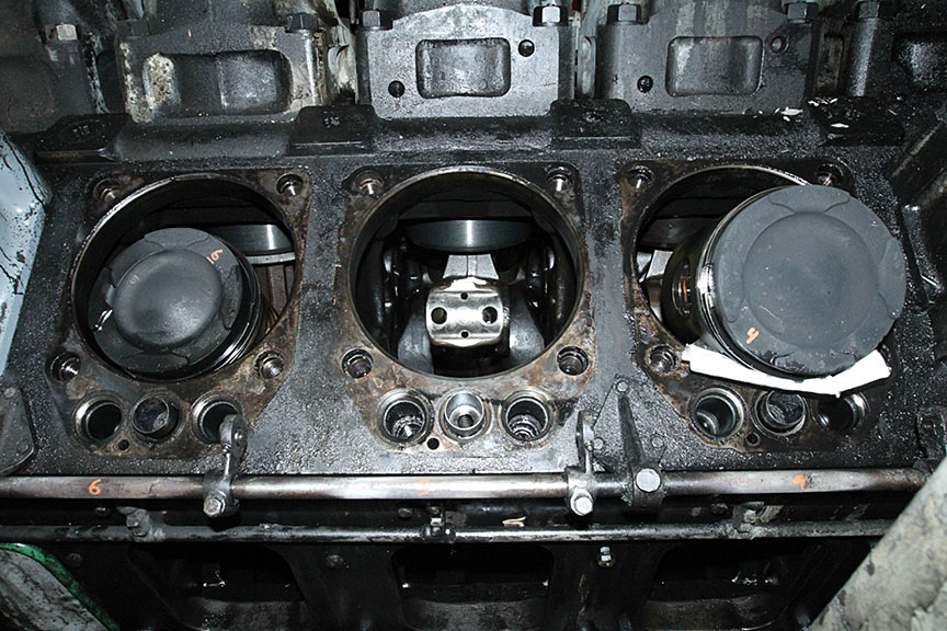
PA R4 and PA R6 were removed for examination. These assemblies were unremarkable apart from some differences in colour. The piston crown of R6 was oily and darker than the colour associated with normal operation. The piston crown of R4 was dry but still a little darker than normal (Figure 24). Removal of the rockers and rocker shafts showed that they were well lubricated and slid apart with ease (Figure 25).

2.3.3
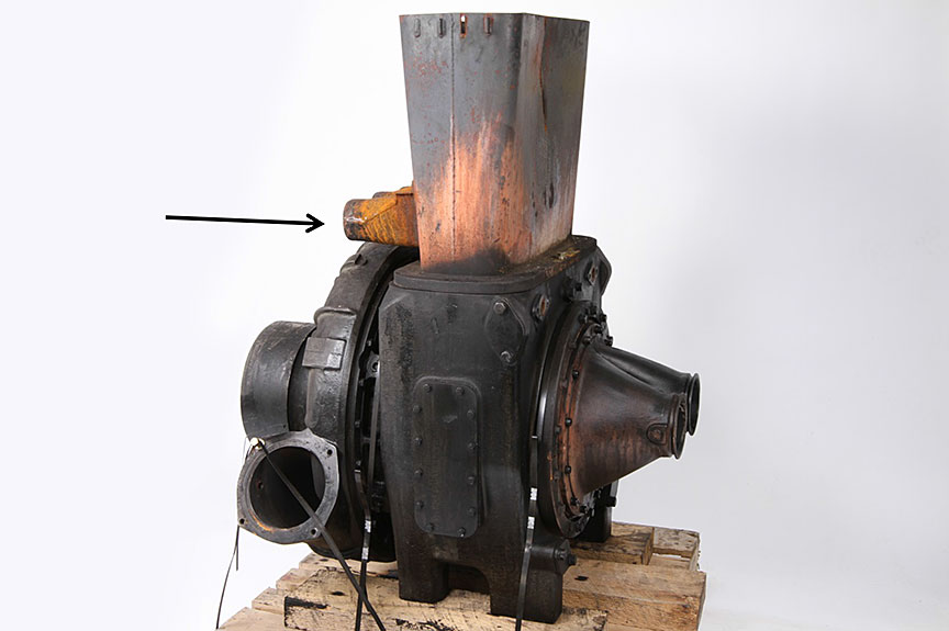
Re-assembly of the exhaust stack and turbocharger out of the locomotive showed the location of the fire with respect to the aspirator venturis in the exhaust stack (Figure 26). The paint and deposits on the body of the turbocharger had not been damaged by the fire whereas the area around the venturis and the lower portion of the exhaust stack were extensively fire damaged as shown by their rusty colour. Removal of the transition section from the turbocharger showed a buildup of oily deposits on the exhaust side (Figure 27). A fragment of valve stem was observed just upstream of the turbine (Figure 28).


2.3.4
Disassembly of the turbocharger showed that approximately 12 of the 70 turbine blades had fractured (Figure 29). The turbine and compressor journal bearings and shaft showed wear damage, primarily on the compressor side (Figures 30 through 34). The wear areas on both the turbine and compressor bearings occurred in three locations radially around the bore of the bearings, between the three equally spaced oil delivery ports. A large quantity of dense oil sludge was found in the body of the turbocharger indicating that oil had been collecting in the turbocharger for some time. However, the oil seals for both the compressor and turbine bearings were in good condition and there was no sign of abnormal leakage (Figure 35).


2.3.5
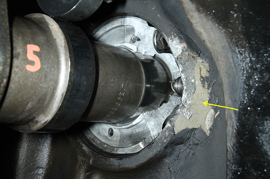
Cleaning of the area around the failed R4/R5 cam bearing revealed that the cam bearing bore had been previously repaired with a polymeric material (likely some type of epoxy) (Figure 36). A portion of the engine frame adjacent to the cam bearing bore had been broken away and replaced with this polymeric material. The repaired area had failed and some of the polymeric material was missing.
2.3.6
A sweep of the engine sump produced the missing pieces of repair material and the fractured portion of cam bearing (Figure 37). In addition, debris originating from several other engine components was recovered in the sump, consistent with an engine failure event pre-dating this occurrence (Figure 38).


2.3.7
The failed cam bearing was removed and an intact bearing was installed in the R4/R5 position to show the extent of unsupported bearing area and the deformation of the cam bearing bore (Figure 39). Figure 40 shows the recovered fragments of polymeric material fitted to the damaged area also indicating the extent of the repair.


2.4 Failed R4/R5 cam bearing
2.4.1
The failed cam bearing had fractured at the mounting bolt hole (Figures 41 and 42). The fracture surface had a rough appearance with ridges pointing back to the outboard end of the bolt hole. This indicates that this was an overstress fracture that had initiated at the mounting bolt hole (Figure 43). No sign of progressive fracture was observed. The R4/R5 cam bearing is manufactured of aluminum alloy with a helical thread steel insert to accept the mounting bolt. Localized thread damage in both the separated portion and the remaining portion of the bearing (Figures 44 through 47) indicate that the fracture originated at the top and bottom of the mounting hole when the material surrounding the steel thread insert was overloaded axially in the outboard direction. The final portion of the thread insert itself was also deformed in the axial direction (Figure 48). The outboard edge of the separated section of bearing had contacted the camshaft resulting in a localized smear (#figure-49 ). These observations suggest that the bolt was over-tightened, overloading the cam bearing material around the threaded insert and causing its overstress fracture at the bolt hole.


3.0 Discussion
3.1
It was reported that locomotive MMA 5017 had experienced a destructive engine failure on 17 October 2012. At that time, PA L5, R5 and R6 as well as cam segments R4, R5 and R6 were replaced as a result of an articulated rod failure on R5. It is considered most probable that the engine block was deformed and fractured at the R4/R5 cam bearing bore during this previous engine-failure event. Normal repair procedures for this type of engine block damage generally require the engine to be disassembled, followed by welding and machining operations to rebuild the missing portion of engine block. In the present case, the damaged engine block was repaired using a polymeric material, which did not have the strength and durability properties required for this type of application. All repair records had been signed and approved by MMA repair and supervisory personnel prior to the locomotive being released from the shop.
3.2
Records show that on 15 March 2013, MMA 5017’s engine was leaking oil at the R4/R5 cam bearing bolt. It is considered likely that the cam bearing mounting bolt had loosened at this location because the bearing was not seating properly in the previously damaged and deformed bearing bore. It is considered most probable that the R4/R5 cam bearing bolt was over-tightened in an effort to stop the leak. As a result, the bolt and threaded insert were pulled out of the cam bearing and the cam bearing separated in overstress. It is not known when the portion of the adjacent polymeric material repair broke off. The repair material failure was adhesive in nature close to the bearing bore indicating the bond between the block and the repair material failed (refer to Figure 36). Further outboard of the cam bearing the repair material failed in a cohesive manner, indicating it was unable to withstand the applied stress. This could have been a result of the oil pressure at start up following the repair or later when the mounting bolt was over-tightened.
3.3
The failure of the R4/R5 cam bearing led to a reduction of the oil supply to the top of the PA R5 valve train since once the bearing was broken, most of the oil in this location would have spilled back into the sump. It is considered most probable that continued operation under these conditions of reduced lubrication eventually caused the exhaust valve stems to begin to seize and slow down. The exhaust valves run hotter and would have been affected sooner than the intake valves. The exhaust valves are opened by direct force from the camshaft/pushrods/rocker arms, but are shut by springs alone. The exhaust valves gradually closed more slowly due to the insufficient lubrication and became unsynchronized with the engine. Eventually, this caused the valves to interact repeatedly with the R5 piston, resulting in bending and/or separation of the valve stems and heads.
3.4
A broken valve stem was trapped between the combustion chamber and the piston, and punctured the R5 piston crown. Normally, engine oil is pumped into the chamber beneath the piston crown for cooling. The puncture in the piston crown now permitted some of this oil to flow into the cylinder. The damaged intake and exhaust valves further allowed the oil to flow from cylinder R5 into both the intake and exhaust manifolds, and eventually, from the exhaust manifold into the body of the turbocharger. Evidence of this oil was observed in the intake and exhaust manifolds during the teardown (refer to Figures 8 through 11).
3.5
At normal train speeds with the engine operating at high RPM, most of the engine oil would have been blown out of the turbocharger. However, when the engine was set to idle after the train stopped at Nantes, the level of engine oil in the turbocharger increased to the point that the excess oil flowed into the left hand side of the exhaust manifold. It is considered most probable that the oil in the exhaust manifolds and the body of the turbocharger became superheated and was ignited by the flame front from the forward cylinders.Footnote 1 This flame then propagated from the exhaust manifold into the turbocharger. The oil collected in the turbocharger, was atomized by the turbine, and then mixed with the combustion air introduced by the aspirator venturis, creating a blow-torch type of fire in the exhaust stack.
3.6
The time between the cam bearing fracture and the exhaust valve failure could not be determined. Although the R4/R5 cam bearing had fractured, little damage was observed on the cam bearing bore or the corresponding cam journal. Likewise, the crossheads showed little damage apart from the accelerated wear observed on the roller for the exhaust crosshead. This indicates that although oil pressure in the area was reduced, oil volume continued. The engine is equipped with a low oil pressure device that will stop the engine and illuminate a warning light in the cab. This was not reported and therefore, it is considered most probable that the oil pressure was sufficient for the engine to keep running. It is considered likely that, although not operating under full pressure, the crossheads served as pumps to deliver some oil to the top of the R5 PA. Although the volume of oil provided would have been insufficient for normal service life, it likely extended the time required for exhaust valve failure.
3.7
Once the exhaust valves began to seize and contact the piston, the time to failure was likely relatively short. Bent valves will not retract properly into their seats and therefore will contact the piston repeatedly. The extent of impact damage to the piston crown and recovered valve pieces indicates that a significant amount of interaction occurred before the valve pieces were ejected from the cylinder. It is considered that operational engine speedsFootnote 2 would have been required to migrate the liberated valve pieces down the exhaust manifold to the turbocharger. Thus it is likely that the valve failure pre-dated the locomotive stopping at Nantes.
4.0 Conclusions
4.1
The R4/R5 cam bearing fractured when the mounting bolt was over-tightened after the R4/R5 cam bearing had been installed in an improperly repaired bore.
4.2
Failure of the R4/R5 cam bearing caused a reduction of the engine oil supply to the valve train at the top of the R5 power assembly. The decreased lubrication eventually led to valve damage and a punctured piston crown in the R5 power assembly.
4.3
The damaged valves and piston crown allowed engine oil to flow into the R5 cylinder, into the intake and exhaust manifolds and to collect in the body of the turbocharger.
4.4
The engine fire occurred in the exhaust stack due to the buildup and subsequent ignition of engine oil in the body of the turbocharger.
4.5
The precipitating event to the cam bearing failure was the temporary repair to the engine block using a polymeric material, which did not have the strength and durability properties required for this type of application.
This lab report is part of the Transportation Safety Board of Canada's investigation report R13D0054.