
TSB Laboratory Report LP184/2013
Table of contents
1.0 Introduction
1.1
On 06 July 2013, a unit train carrying petroleum crude oil operated by Montreal, Maine & Atlantic Railway (MMA) derailed in Lac-Mégantic, Quebec. The train consisted of 5 head-end locomotives, 1 VB car (special purpose caboose), 1 box car, and 72 Class 111 tank cars. Sixty-three (63) of the tank cars and the 1 box car derailed. Numerous tank cars ruptured, and a fire ensued. The 5 locomotives and VB car did not derail and travelled approximately 4435 feet past the point of derailment before coming to rest.
1.2
During the field investigation it was noted that the knuckle and pin from the aft end of the number 2 locomotive (MMA 5026) had failed (Figure 1). The knuckle on the forward end of the box car (CIBX 172032) had also failed (Figure 2). The 2 knuckles were sent to the Transportation Safety Board of Canada (TSB) Engineering Laboratory to determine the possible cause of the failures.


1.3
The knuckle is the part of the coupler which engages with the mating coupler. It is controlled through internal linkages inside the coupler that allow the knuckle to open and to close, locking in the engaged position. The pin that had failed on the locomotive knuckle acts as a pivot point for the knuckle when opening and closing.
2.0 Examination
2.1
The knuckles from the locomotive and box car are shown as received in Figure 3 and Figure 4. Table 1 shows the markings that were observed on the knuckles.


| Locomotive knuckle | Locomotive knuckle pin | Box car knuckle | Marking significance |
|---|---|---|---|
| F51AC | - | E50ARE | Part number |
| 1223 | - | 8690 | Serial number |
| M&T | GB | M&T | Manufacturer |
2.2 Locomotive knuckle and pin
2.2.1
The knuckle and pin were cleaned for examination. The fracture surfaces from the locomotive knuckle and pin are shown in Figure 5 and Figure 6, respectively. Figure 7 is a close-up of the area adjacent to the inner radius of the knuckle where fatigue cracks were visible on the fracture surface. The fatigue cracks had a dark rusty appearance suggesting they had been present for some time. The remaining fracture surface had a rough appearance consistent with an overstress mode of failure. Shear lips on the side opposite to the fatigue region and the orientation of ridges on the fracture surface indicate the direction of failure from the inner to the outer radius (refer to arrows on Figure 8), consistent with a tensile load acting on the knuckle.


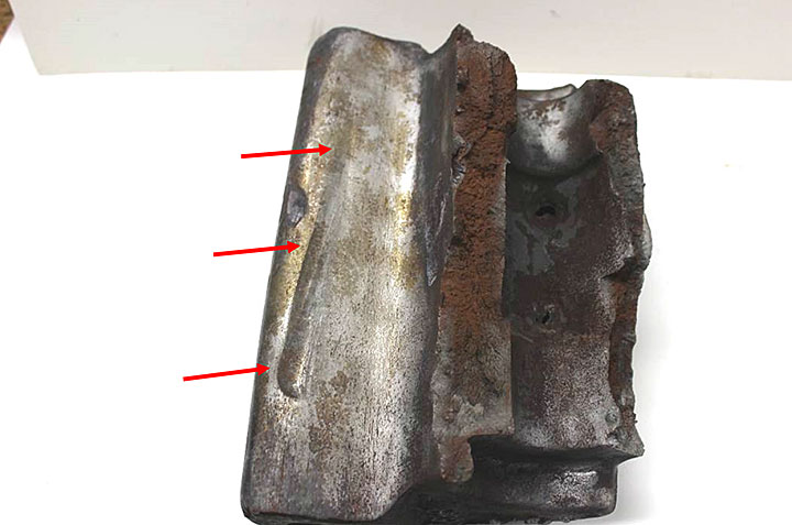
2.2.2
Mechanical damage, parallel scoring and secondary cracks were noted on the inner radius adjacent to the fatigue region (Figure 9). The appearance of the scoring damage was consistent with grinder marks. The secondary cracks likely opened as a result of the tensile loads that caused the knuckle failure.

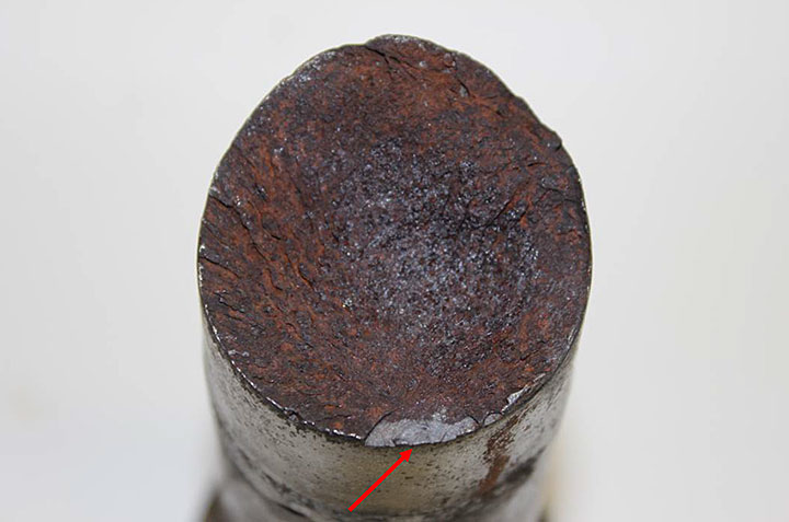
2.2.3
The knuckle pin had a total shank length of 13 ½ inches and it had fractured 3 inches below the head (Figure 6). The fracture surface of the pin contained a small pre-existing fatigue crack approximately 10 mm wide by 4 mm deep. The remaining fracture surface exhibited a rough appearance with ridges originating from the small fatigue crack, consistent with overstress caused by a bending load. The fatigue crack most likely acted as a location site for the failure of the pin.
2.2.4
A metallurgical section was taken through the fatigue crack in the inner radius of the knuckle. Chemical etching in a 2% Nital solution revealed a quenched and tempered martensite microstructure (Figure 10). The metallurgical cross-section also exhibited small secondary cracks at the inner radius surface of the knuckle (a representative example is shown in Figure 11). There was no sign of a transformed microstructure that might be indicative of thermal damage caused by grinding.


2.2.5
Direct Rockwell A hardness testing of the locomotive knuckle material gave an average value of 59.6 HRA, which is equivalent to 222 HBW and within the AAR specification rangeFootnote 1 of 211 to 311 HBW for this class of knuckle.
2.2.6
Standardless energy dispersive x-ray spectroscopy (EDS) analysis of the locomotive knuckle material gave manganese, chromium and silicon contents consistent with the AAR specification. The concentrations of carbon, sulphur and phosphorus were not determined.
2.3 Box car knuckle
2.3.1
The fracture surfaces of the box car knuckle were cleaned for examination. A small area adjacent to the inner radius of this knuckle had a porous granular appearance consistent with a casting flaw (Figure 12). A small fatigue crack was associated with this casting flaw. The remaining fracture surface was overstress in nature (Figure 13). The orientation of the shear lips on the inner and outer sides of the fracture surface indicates that the knuckle failed from a torsional load (refer to arrows on Figure 13). The knuckle had an impact mark on the portion that engages with the mating knuckle (Figure 14). This impact mark was offset in the upward direction. The direction of the torsional load indicated by the shear lips and the location of the impact mark are consistent with the box car leaning to the left side as it was derailing and finally coming to rest on its left side.


2.3.2
A metallurgical section was taken adjacent to the area of fatigue. Chemical etching in 2% Nital solution revealed a quenched and tempered martensite microstructure (Figure 15).

2.3.3
Direct Rockwell A hardness testing of the box car knuckle material gave an average value of 64.8 HRA, which is equivalent to 279 HBW and within the AAR specification rangeFootnote 2 of 211 to 311 HBW for this class of knuckle.
2.3.4
Standardless EDS analysis of the box car knuckle material gave manganese, chromium and silicon contents consistent with the AAR specification. The concentrations of carbon, sulphur and phosphorus were not determined.
3.0 Discussion
3.1
The examination of the locomotive knuckle and pin indicates that both failed in overstress. It is considered most probable that due to their small size, the fatigue cracks on the inner radius of the knuckle would not have significantly reduced its load-bearing capacity and merely acted to locate the fracture. The section of knuckle that separated from the locomotive coupler was found near the location where the locomotives came to rest, approximately 4435 feet from the main derailment site.
3.2
The orientation of the shear lips and location of the impact mark on the box car knuckle indicate that this failure occurred under a torsional load when the box car derailed and landed on its left side. It is considered most probable that due to their small size, the pre-existing casting flaw and fatigue crack observed in the knuckle did not affect its load-bearing capacity and merely acted to locate the fracture.
4.0 Conclusion
4.1
The locomotive knuckle failed in a tensile overstress mode initiating at a pre-existing fatigue crack on the inner radius of the knuckle. This fatigue crack merely acted as a location site for the failure of the knuckle.
4.2
The fatigue crack observed on the locomotive knuckle was most likely present for some time and may have initiated from the mechanical damage observed on the inner radius of the knuckle. This mechanical damage was most likely caused by grinding.
4.3
The locomotive knuckle material met the applicable AAR requirements.
4.4
The locomotive knuckle pin failed in a bending overstress mode which initiated at a pre-existing fatigue crack. This fatigue crack merely acted as a location for the failure and had the appearance that it was present for some time.
4.5
The box car knuckle failed from a torsional overstress mode. A small pre-existing casting flaw and fatigue crack likely acted as an initiation site for the failure.
4.6
The box car knuckle material met the applicable AAR requirements.
This lab report is part of the Transportation Safety Board of Canada's investigation report R13D0054.