
TSB Laboratory Report LP007/2014
Tear Down of Hand Brakes - Montreal, Maine & Atlantic Railway, Train MMA-002
Project Summary
On 06 July 2013 Montreal, Maine & Atlantic Railway (MMA) freight train MMA-002, en route from Montréal, Quebec, to Saint John, New Brunswick, was stopped at Nantes, Quebec (Mile 7.40 of the Sherbrooke Subdivision). The train, consisting of 5 head-end locomotives, 1 VB car (special purpose caboose), 1 box car, and 72 Class 111 tank cars carrying flammable liquids (petroleum crude oil, UN 1267, Class 3), was secured on the main track on a descending grade. Shortly before 0100 on 06 July 2013, the train started to move and gathered speed as it rolled uncontrolled down the descending grade into the town of Lac-Mégantic, Quebec, 7.4 miles southeast of Nantes. While travelling at well in excess of the authorized speed, the train derailed near the centre of Lac-Mégantic. Numerous tank cars ruptured and a fire ensued.
Handbrakes from the first three derailed tank cars were removed and forwarded to the Engineering Laboratory of the Transportation Safety Board of Canada for examination.
| Handbrake | Car | Position in consist | Handbrake manufacturer | Date of manufacture |
|---|---|---|---|---|
| 1 | TILX 316547 | 3 | Klassing 1700 | 08/11 |
| 2 | WFIX 130608 | 4 | Klassing 1700 | 07/11 |
| 3 | TILX 316359 | 5 | Klassing 1700 | 06/11 |
The three handbrakes were photographed as received before examination (Figure 1). The handwheels from handbrakes 1 and 2 had been previously removed prior to shipping to the TSB laboratory but were temporarily replaced for the photographs. It is not known whether the handbrakes had been operated following the occurrence. The three handbrakes were in the released position with the upper chain attachment point clearly visible. White paint residue was visible at the upper chain attachment point on all the handbrakes although mostly removed due to fire damage on number one (Figure 2). The back plate of handbrake number 1 showed deformation (Figure 3) whereas the other two did not. The handwheel and release handle were removed from each handbrake. The nut used to secure the release handle had been welded to its shaft in each case and had to be cut before removal. The heads of the solid rivets used to join the front housing to the back plate were cut using an abrasive disc and the housing was lifted off (Figure 4).
The pitch of the smaller (pinion) gear and the larger (ring) gear of each handbrake was visually examined. There was no sign of gear damage on any of the handbrakes that would indicate that they had been in the applied position at the time of the occurrence (Figures 5 and 6).
Figure 1. Three handbrakes as received, front view. Note position of upper chain attachment point (arrows)
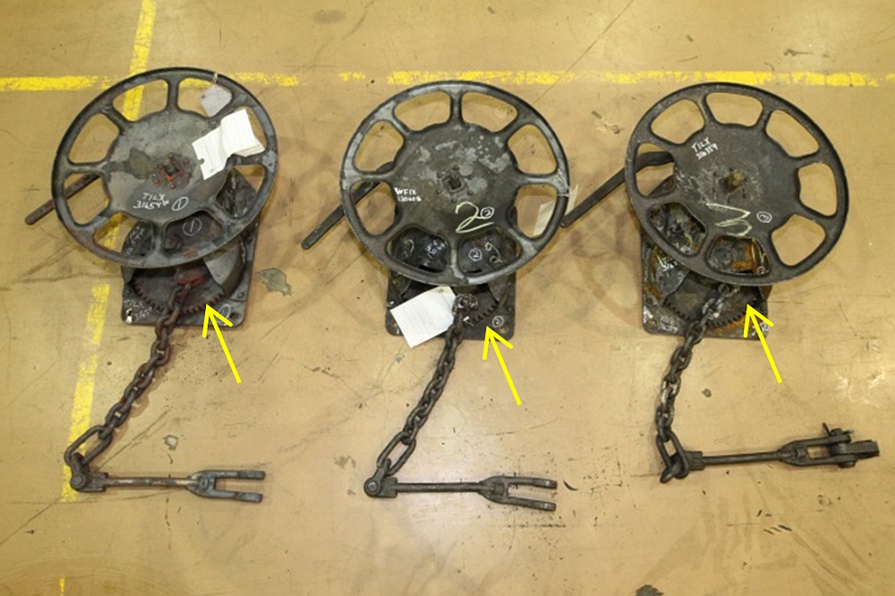
Figure 2. Handbrake 2 handwheel removed. Note white paint residue on chain (arrow)

Figure 3. Handbrake 1 showing back plate deformation

Figure 4. Handbrake 1 showing housing removed

Figure 5. Pinion gear of handbrake 3. Note uniform gear tooth pitch (arrow)

Figure 6. Ring gear of handbrake 1. Note uniform gear tooth pitch

This lab report is part of the Transportation Safety Board of Canada's investigation report R13D0054.