
TSB Laboratory Report LP039/2014
Table of contents
1.0 Introduction
1.1 Description of occurrence
1.1.1
On 06 July 2013, at approximately 0115 Eastern Daylight Time (EDT), Montreal, Maine & Atlantic (MMA) freight train MMA-02 carrying petroleum crude oil derailed in the town of Lac-Mégantic, Quebec. Numerous tank cars ruptured, lost their content and a fire ensued.
1.2 Engineering services requested
1.2.1
A request was received from the Transportation Safety Board of Canada (TSB) Eastern Regional Operations - Rail/Pipeline office to estimate the derailment speed of individual tank cars involved in the occurrence.
1.3 Background
1.3.1
The train consisted of 5 head-end locomotives, 1 VB car (special purpose caboose), 1 box car, and 72 Class 111 tank cars carrying flammable liquids (petroleum crude oil, UN 1267, Class 3). Sixty-three (63) tank cars and the box car derailed. The 9 tail-end tank cars had not derailed and were subsequently pulled back to Nantes as part of the emergency response. The last tank car to derail (NATX 310470, consist no. 65) was basically undamaged and it was re-railed and pulled back from the pileup during the wreckage clearing operations.
1.3.2
The investigation revealed that when the emergency brake signal was ON, the speed of the train was 65 miles per hour (mph).Footnote 1
1.3.3
The train stopped after tank car NATX 310470 (63rd tank car) derailed.
1.3.4
The train was on a downhill grade (G) of about 1.2% before the point of derailment.Footnote 2
1.3.5
The length of a representative tank car (between the coupler pulling faces) was 60 feetFootnote 3 (18.30 meters). The gross weight of the derailed tank cars was 128 tons (116 metric tons) on average.
2.0 Analysis
2.1
Figure 1 is a diagram schematically illustrating the derailment of the freight train. It is presumed that at the moment when the tank car derails (Figure 1a), it has the same speed as that of the remaining train. Thus, by estimating the speed of the remaining train, the derailment speed of the tank car can be obtained.

2.2
The estimation of the speed of the remaining train is carried out based on the kinetic energy equilibrium method. There are several assumptions for the model:
- The remaining train is a rigid body.
- The point of derailment for all the tank cars does not change. This implies that when the car derails, the remaining train would still remain on the track and push it forward until the car arrives at the same spot and begins to derail, as shown in Figure 1a through 1c.
- When the car derails, its sudden deceleration would produce an impeding force ( ) against the travelling of the remaining train due to the interaction between the derailed tank car and the remaining train. Essentially the impeding force is a reaction force to the force applied by the remaining train on the derailed tank car to overcome its friction with the ground in order to push it forward. A detailed analysis of the impeding force against the remaining train is presented in Appendix A. Based on this analysis, a constant impeding force value can be used for a first order estimation of the speed of the remaining train using the energy equilibrium method.
- The first derailed car was a box car (CIBX 172032), which had a length of 69 feet and a gross weight of 105 tons. For the purpose of simplifying the calculation, it will be treated as having the same physical parameters as the derailed tank cars (see paragraph 1.3.5).
2.3
The train has tank cars ( in this case) and each tank car has a mass (in this case, metric tons=116,000 kg).
2.4
Presuming the car is derailed, at the beginning of its derailment (as shown in Figure 1a), the parameters of the remaining train are:
- speed,
- mass of the remaining train,
- impeding force from the derailed tank car against the remaining train,
- gravity force on the train
(1)(here, G is the downhill grade of the track and g is the gravity constant 9.8 m/s2)Footnote 4 - kinetic energy of the remaining train
(2)
2.5
At the end of the car’s derailment (Figure 1c), the moment when the body of car is completely pushed outside the track by the remaining train and the car arrives at the derailment point, but still remains on the track, the parameters of the remaining train are:
- speed,
- mass of the remaining train remains the same,
- impeding force from the derailed car against the remaining train still remains a constant
- kinetic energy of the remaining
(3)
2.6
The kinetic energy equilibrium for the remaining train during the process of the tank car’s derailment (over the distance which is the length of the car) is:
-
(4)
Here:
-
is the loss of kinetic energy of the train due to overcoming the impeding force
over the distance
:
(5) -
is the kinetic energy gained by the train due to the gravity force
pulling on the train over the distance
:
(6)
Substituting (1) into (6), it is obtained:
Further substituting (2), (3), (5) and (7) into (4), it is obtained:
Thus,
2.7
When the derailment of the car is completed, the following tank car starts its derailment, as shown in Figure 1d. The remaining train has cars with movement speed . It is also presumed that:
At the end of the derailment of the car (when this car is completely pushed outside of the track by the remaining train), it can be obtained:
The sequence goes on until the 64th car (63rd tank car) derails, which stops the travelling of the remaining train.
2.8
The calculation has to meet the initial and final boundary conditions. Two scenarios are considered based on which tank car derailed first.
Scenario 1
The box car CIBX 172032 (consist no.2) is assumed to be the first one derailed. The initial condition is:
The final condition is reached when the 64th car (63rd tank car) derails and the remaining tank cars stop:
Scenario 2
The 6th car TILX 316338 (consist no.6, also the 5th tank car if the box car is treated as a tank car) is assumed to be the first one derailed.Footnote 5 The initial condition is:
The final condition is identical to the final condition listed for scenario 1.
2.9
The impeding force, assumed to be a constant, against the travelling of the train is unknown, but the calculation can be performed to determine the for given values ranging from 10,000 N to 2,500,000 N with incremental steps of 100 N. This calculation is iterated until an value is identified that satisfies the boundary conditions for each scenario. This value is then employed to calculate the speed of the remaining train as a function of the number of cars that have already derailed.
2.10
The impeding force values thus obtained for the 2 scenarios listed in section 2.8 are as follows:
- for scenario 1, the average impeding force obtained is 1,746,400 N
- for scenario 2, the average impeding force obtained is 1,805,400 N
2.11
The speed of the remaining train versus the number of derailed tank cars is then calculated using the estimated average impeding force for each scenario. Since the speed of the remaining train is presumed to be the same as that of the derailed tank car in front of it, this calculation provides an estimate of the derailment speed ofindividual tank cars for the above 2 scenarios, which are plotted in Figure 2.

2.12
Once the derailment speed of individual tank cars has been calculated, an estimate of the total time for derailment of the whole train can also be made based on following equation:
For scenario 2 where , the total derailment time would be approximately 58 seconds.
3.0 Discussion
3.1
The above analysis is considered to be a first order approximation of the derailment speed of individual tank cars based on an idealized and constant impeding force against the movement of the remaining train still on the track.
3.2
The analysis was performed based on a presumption that there is always a derailed tank car in front of the remaining train, linked by the couplers. While there could be impacts among the derailed tank cars with rather complex impact forces involved, the remaining train does not impact directly with the derailed tank cars. Thus the force interaction between the remaining train and the derailed tank cars is considered to be relatively simple and is limited to the forces required to overcome the friction between the derailed tank cars (connected to the remaining train) and the ground, to rotate the derailed tank cars and to cause the decoupling of the couplers.
3.3
Higher order estimation of the derailment speed would require detailed modelling of the impeding force based on an understanding of the derailment mechanism and collision scenario between the derailed tank cars.
3.4
The results obtained using the present approach suggest that most tank cars were travelling at a speed greater than 50 mph when they derailed.
3.5
Table 1 shows a breakdown of the number of tank cars as a function of their estimated derailment speed. It can be seen that approximately 10 tank cars would have been travelling at a speed of 40 mph or less when they derailed.
| Scenario | Number of cars at estimated derailment speed | ||
|---|---|---|---|
| Under 20 mph | Under 30 mph | Under 40 mph | |
| 1 | 2 | 4 | 9 |
| 2 | 2 | 5 | 10 |
4.0 Conclusions
4.1
The analysis suggests that most tank cars were travelling at more than 50 mph when they derailed.
4.2
The remaining train would have been travelling at less than 20 mph when the last 2 tank cars derailed.
4.3
The remaining train would have been travelling at less than 30 mph when the last 5 tank cars derailed.
4.4
The remaining train would have been travelling at less than 40 mph when the last 10 tank cars derailed.
Appendix A - Analysis of impeding force against the remaining train
A-1.0 Introduction
A-1.1
To estimate the speed reduction of the remaining train using the kinetic energy equilibrium method, it is necessary to understand the impeding force against the travelling of the remaining train in order to derive a representative force for the calculation or modelling.
A-1.2
The process of the train’s derailment may be divided into three stages to simplify the analysis:
- During the first stage, the derailed tank cars are presumed to travel in line on the ground with their couplers still engaged. A limited number of derailed cars would have been involved in this stage;
- The second stage starts when the derailed tank cars begin to rotate relative to their direction of travel, forming a curved or zigzagged column consisting of derailed cars braced by the couplers, and finishes when this zigzagged column collapses;
- The final stage starts when a car derails, rotates to an angle with respect to the track and is pushed forward by the remaining train to impact with the derailed cars in front, breaking the coupling between the couplers and causing the next tank car to derail. This process is repeated until the remaining train is stopped by the impeding force.
A-2.0 Impeding force during the first stage
A-2.1
Figure A-1 is a schematic illustration of the impeding force against the travelling of the remaining train during the first stage.

A-2.2
The train is moving on the track without a locomotive when the first car derails, as shown in Figure A-1a. Two more tank cars then derail and are added to the chain of derailed tank cars, as shown in Figure A-1b.
A-2.3
The rolling friction between the wheels of the remaining train and the track is neglected. Also neglected is the resistance force from the wind against the travelling of the remaining train.
A-2.4
The friction force between the wheels of the derailed car and the ground is significant in that the remaining train needs to exert a force ( ) to overcome this friction force to maintain the travelling speed of the derailed cars.
Thus,
Here:
- is the number of tank cars that have derailed during the first stage of the derailment; is the mass of a derailed tank car;
- is the coefficient of friction between a derailed tank car and the ground, typically ranging from 0.25 to 0.75.Footnote 6
Assuming a coefficient of friction ( ) of 0.4 (a reasonable assumption for travel in the wheels’ rolling direction), the force ( ) required to push one derailed car forward ( ) is estimated to be 0.45 MN.Footnote 7
A-2.5
There is a reaction force ( ) to the force ( ) exerted by the remaining train on the derailed car. It produces two force components, and , as shown in Figure A-1a. While works directly as an impeding force against the travelling of the remaining train, works to push the wheels of the train against the side of the track to introduce a friction force against the travelling of the remaining train. Thus the impeding force against the train ( ) is actually a complex force, which is defined as:
Here is the non-rolling coefficient of frictionbetween the wheels of the remaining train and the track.
Presuming the angle of the reaction force ( ) with respect to the longitudinal direction of the remaining train (or the track) is 5° (about 1/8 between 0 and the maximum angle allowed by the geometry constraints between 2 tank cars) and is 0.3 (an average value for the coefficient of friction when the wheels slide on the track) Footnote 8, one derailed tank car would produce an estimated impeding force of 0.47 MN.
A-2.6
From equation A2, it can be seen that the impeding force ( ) is a function of the total number of cars derailed in this stage. The impeding force will increase linearly with the increase in the number of cars derailed during this stage as long as the derailed cars are in a line.Footnote 9
A-3.0 Impeding force during the second stage
A-3.1
As the impeding force ( ) continues to rise with the increase in the number of cars derailed (section A-2.6), at one point it will become sufficient to cause the rotation of the derailed tank car as shown in Figure A-2a. This is because the derailed tank cars will not be perfectly aligned with each other as well as with the direction of the force applied by the remaining train.

A-3.2
The pivot (point of rotation) is the joint of two couplers as shown in Figure A-2a. Using the moment equilibrium method, the force ( ) required for the derailed tank car (highlighted in yellow in Figure 2a) to rotate can be defined as:
Thus,
Here,
- is the length of the tank car between the couplers
- is the friction force between the tank car and the ground in the tangent direction of the rotation (perpendicular to the longitudinal direction of the tank car), applied on the center of gravity of the car
- is the angle of the force ( ) with respect to the longitudinal direction of the tank car
A value of 0.75 is presumed for the coefficient of friction ( ) between the tank car and the ground (this is reasonable considering it is in the direction perpendicular to the wheels’ rolling direction). 6 The angle ( ) at which rotation begins is unknown; however, assuming it is 5° (about 1/8 between 0 and the maximum angle allowed by the geometry constraints between 2 tank cars), the force ( ) for beginning of rotation is estimated to be 4.9 MN using equation A5. Referring back to the result for estimated for one derailed tank car (section A-2.5), this result suggests that approximately 10 tank cars would have derailed before the force applied on the derailed tank car by the remaining train would cause it to rotate.
A-3.3
Once the derailed tank car starts to rotate, the force required for rotation ( ) will decrease because the angle ( ) in equation A5 increases as the rotation proceeds. Consequently the impeding force against the travelling of the remaining train will also decrease.
A-3.4
As a result of the geometric constraints between two adjacent cars linked by couplers, the rotation of the derailed car causes the corners of the two cars to come into contact under a compressive force. At the same time, the force on the coupler changes from compression to tension, as shown in Figure A-2b. This rotation triggers a chain reaction of rotations in the rest of the derailed tank cars because all these tank cars are linked by their couplers, subsequently forming either a curved or an alternating-direction buckling pattern,Footnote 10 as shown respectively in Figure A-2c and Figure A-2d.
A-3.5
Such a configuration is in effect a structural column consisting of the derailed tanks car braced by the couplers. Once formed, it will increase the impeding force against the travelling of the remaining train due to the significant increase in the coefficient of friction between the tank cars and the ground when the cars’ direction of travel is not aligned with their longitudinal axis (wheel rolling direction).
A-3.6
As more derailed cars are added to the column of derailed tank cars, the force required to push them forward continues to rise, causing a concomitant increase of the impeding force to the remaining train. At some point, the increase in the applied force ( ) will be sufficient to cause the decoupling of the couplers, separating adjacent tank cars, as shown in Figure A-2e.
A-3.7
The force exerted by the remaining train to break the coupler-stiffened column can be estimated using the force diagram shown in Figure A-3:
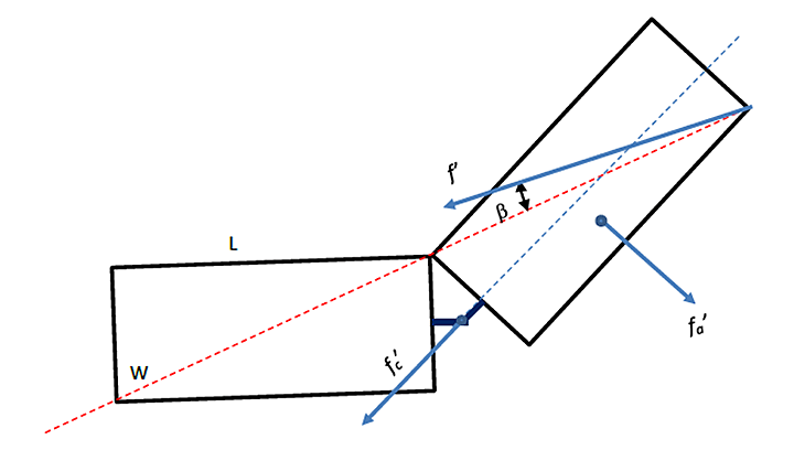
Here
- and are the length and width of the tank car, respectively.
- is the maximum coupling force of the couplers.
- β is the angle of applied force by the remaining train with respect to the longitudinal axis of the column of derailed tank cars.
Engineering drawings for the subject tank cars indicate L = 17.7 m and W = 3.0 m.
The coefficient of friction is presumed to be 0.75 as indicated previously (section A-3.2).
The decoupling force for the couplers is taken to be the breaking force limit (ultimate strength) of knuckles for freight service, ranging from 550,000 lbs to 900,000 lbsFootnote 11 (corresponding to 2,450 to 4,000 kN). A knuckle strength of 3,000 kN is assumed for the purpose of this calculation.
When the column of derailed tank cars is formed, its longitudinal axis is the diagonal line going through the corners of the tank cars in contact, as indicated by the red dotted line in Figure A-3. The angle between the applied force ( ) and the longitudinal axis of the column is unknown, but again presumed to be 5°.
Based on the above parameters, the force ( ) required to break the coupling between two couplers and to cause the cars to collapse is estimated to be around 7 MN. The impeding force ( ) is also estimated to be around 7 MN using equation A2 and assigning = .
A-4.0 Impeding force during the third stage
A-4.1
When the column of derailed tank cars collapses, it will cause the derailment of the next tank car, as shown in Figure A-4a.

A-4.2
The remaining train will push the derailed car forward. The force needed to push one derailed tank car forward was estimated to be about 0.45 MN (section A-2.4). Before the next car can derail, it will also be pushed by the remaining train until it impacts with the derailed car in front (Figure A-4b). This will break the coupling between the two cars, separating the front car from the remaining train and causing the derailment of the next car, as shown in Figure A-4c. The force required to break the coupling was estimated at about 7 MN as presented in section A-3.7. Thus the impeding force against the travelling of the remaining train will also rise to this level in a very shorttime before returning to the lower level corresponding to the force required to push one derailed car forward. The remaining tank cars will derail following the repeated steps schematically presented in Figure A-4, with the reiteration of an impeding force cycle that spikes from 0.45 MN to 7 MN and returns to 0.45 MN in short pulses (one per tank car), until the remaining train stops.
A-5.0 Impeding force profile
A-5.1
Figure A-5 is a schematic illustration of the impeding force profile. The integration of the impeding force over the distance travelled by the train gives the total work produced by the impeding force to reduce the speed of the remaining train. Dividing the total work by the distance travelled by the train gives a constant, average force experienced by the remaining train. This constant force can thus be used as a representative impeding force to estimate the speed of the remaining train under the kinetic energy equilibrium method, as detailed in the main body of the report.

This lab report is part of the Transportation Safety Board of Canada's investigation report R13D0054.