
Supporting technical information A98H0003
Associated links (A98H0003)
-
Table of contents
- Ventilation, cooling, and recirculation fans
- Aft chiller ventilation fan
- Avionics compartment cooling fan
- CAC cooling fans 1 and 2
- Avionics compartment exhaust fan
- Avionics venturi valve
- Aft tunnel venturi valve
- Avionics rack cooling fans
- Forward cargo compartment ventilation fan
- Aft cargo compartment ventilation fan
- Cabin individual air fan
- Cabin air recirculation fans
- Aft tunnel cooling fan
Electrical fans
Ventilation, cooling, and recirculation fans
Electrical fans are used to ventilate and cool the avionics and the centre accessory compartments; to ventilate the galleys, lavatories, and the forward and aft cargo compartments; to recirculate cabin air; and to supply cooling air to the individual seat locations.
Examination
The following five fans share PN 034964:
- Aft chiller ventilation fan
- Avionics compartment cooling fan
- CAC Cooling Fan 1
- CAC Cooling Fan 2
- Forward chiller ventilation fan
All of the above fans were recovered and identified except for the forward chiller ventilation fan.The damage to the fans was used for comparative analysis to determine the operational state of the fans at the time of impact. The operational state of the fans was subsequently used to determine the electrical condition of the aircraft at the time of impact.
Determination
The following aircraft electrical buses were determined to have been electrically powered at the time of impact:
| Electrical Bus | Fan |
|---|---|
| 115 V AC Bus 1 | CAC Cooling Fan 1 |
| 115 V AC Bus 2 | Avionics compartment cooling fan |
Based on the examination of the cabin air recirculation fans, it was also determined that 115 V AC Bus 1 or Bus 3 or both were electrically powered at the time of impact.
Aft chiller ventilation fan
Description
The aft chiller ventilation fan is located in the rear of the aircraft in the aft wall of Lavatory J. The fan is powered by the 115 V AC Bus 3 through the aft chiller vent fan relay. The aft chiller ventilation fan relay is controlled by a ground sensing relay that limits the operation of the fan to ground operations.
Examination
The fan was recovered intact and contained within its mounting structure. The fan was identified by tag as EG&G Rotron PN 034964, SN AFN377. The outer housing wall exhibited minor rotational scuff marks in the blade tip path. Some minor aircraft debris was also noted downstream of the blades.
Determination
Its location was determined by its mounting structure and by its description in the MD-11 Maintenance Manual (Company Edition). Because the aft chiller ventilation fan is only powered on the ground, the minor rotational damage is consistent with the fan being rotated during impact by the ingestion of water and debris.
Avionics compartment cooling fan
Description
This fan, also known as the avionics compartment flow balancing fan, is located below the floor in the right utility tunnel of the forward cargo compartment at fuselage STA 615. The fan blows cooling air from the tunnel into the avionics compartment. It is powered by the 115 V AC Bus 2 through a 5 A, three-phase CB B1-357 located at position M-11 on the upper main CB panel. The continuous operation of the fan depends on the continuous supply of power to the 115 V AC Bus 2. The fan is rated 2.5 A at 11 500 rpm.
Examination
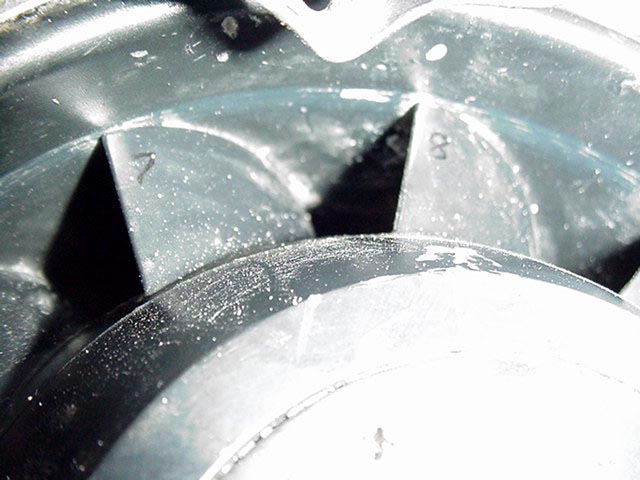
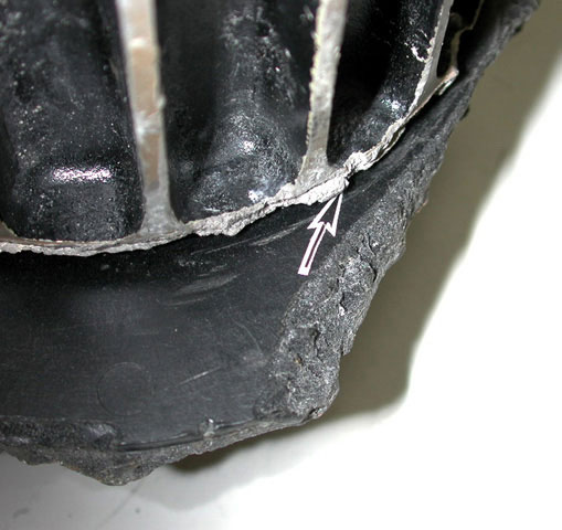
The fan was recovered as a single unit. It was identified by tag as EG&G Rotron PN 034964, SN A01556, and Swissair ASN 0001, IDN 474986.The fan retained a metal V-shaped band clamp on the fan housing inlet, but the associated ducting had broken away. The fan housing was broken at mid-span, adjacent to the stator blades on the exhaust or fan outlet side (which faces forward in the aircraft).

The impeller fairing was dented and the bearing housing, located below the fairing, was pulled away from the fan motor. The fan blade impeller and armature had been driven forward approximately 1/8 inch in relation to the outer housing.
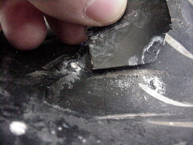
Five of the eleven fan impeller blades exhibited varying degrees of damage to the leading edges and one blade had broken away. The inner circumference of the fan housing exhibited two different patterns of rotational marks.


Determination
Its location was determined by its description in the MD-11 Maintenance Manual (Company Edition). The first pattern of rotational marks on the inner circumference of the fan housing is consistent with contact with the tip of the fan impeller blade in the normal plane of rotation. The second pattern of rotational marks is consistent with contact with the tip of the fan impeller blade in an altered plane of rotation. The altered plane of rotation is consistent with a shift of the armature.The rotational marks on the inner fan housing and the damage to the leading edge of the blade are consistent with a high level of rotational energy of the fan impeller at the time of impact. The damage is consistent with the fan being electrically powered at the time of impact. In order for the fan to be electrically powered, the 115 V AC Bus 2 must have been electrically powered at the time of impact.
CAC cooling fans 1 and 2
Description
The two CAC fans are located below the floor in the right utility tunnel at fuselage STA 660, near the aft right hand side of the forward cargo compartment. The fans cool the CAC electrical and electronic equipment by moving cool air from the right utility tunnel into a ventilation manifold. Air from the ventilation manifold is directed into one side of the avionics rack and then out through the top of the equipment. Flow sensing switches in the ventilation ducts continuously monitor the fans' airflow and send inputs to the ESC. If the primary CAC Cooling Fan 1 does not provide a sufficient flow of air to the ventilation ducts, the ESC will engage CAC Cooling Fan 2.
CAC cooling fan 1
CAC Cooling Fan 1 is powered by the 115 V AC Bus 1 through a 5 A, three-phase CB B1-270 located at position L-18 on the upper main CB panel. The 115 V AC Bus 1 is connected to CAC Cooling Fan 1 through relay R2-5735, which is controlled by the ESC. The ESC energizes relay R2-5735 to shut off CAC Cooling Fan 1.
CAC cooling fan 2
CAC Cooling Fan 2 is powered by the 115 V AC Bus 2 through the 5 A, three-phase CB B1-285 located at position M-18 on the upper main CB panel. The 115 V AC Bus 2 is connected to CAC Cooling Fan 2 through relay R2-5736, which is controlled by the ESC. The ESC energizes relay R2-5736 to turn on CAC Cooling Fan 2.
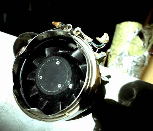
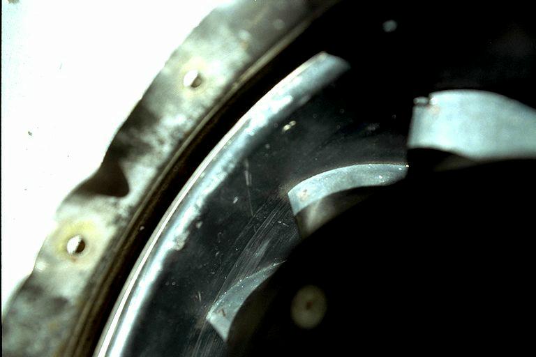
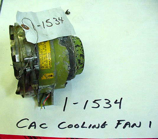
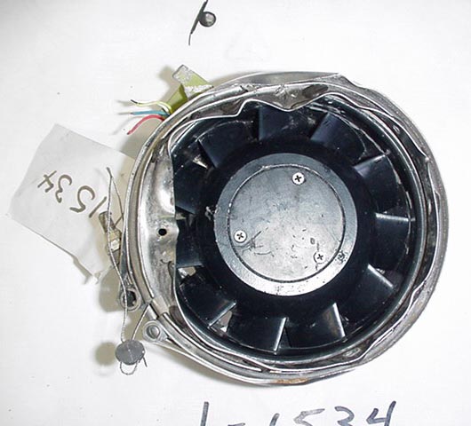
Examination
CAC cooling fan 1
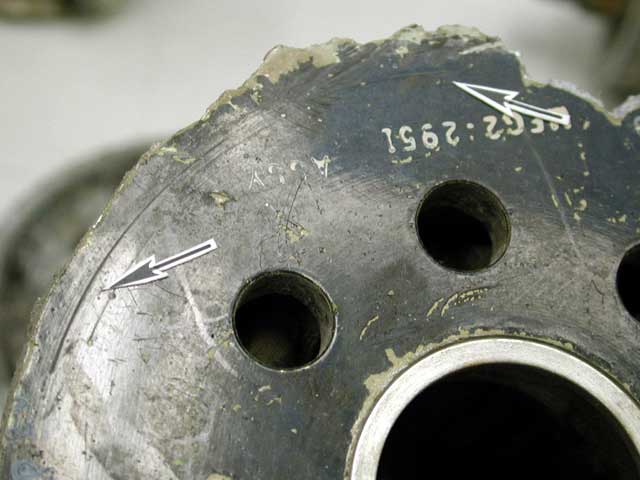
CAC Cooling Fan 1 was recovered as a single unit. It was identified by tag as EG&G Rotron PN 034964, SN A02957, and Swissair ASN 0427, IDN 474986.
The fan retained a metal V-shaped band clamp on the fan housing inlet, but the associated ducting was broken away. The fan housing was broken at mid-span on the exhaust side (which faces aft in the aircraft), adjacent to the stator blades.
The impeller fairing was not recovered. The fan blade impeller was recovered intact. A light score pattern approximately .090 inches wide was observed around the full circumference of the inner housing.


CAC cooling fan 2
CAC Cooling Fan 2 was recovered as a single unit. It was identified by tag as EG&G Rotron PN 034964, SN A04360, and Swissair ASN 0167, IDN 474986.
The fan housing was broken at mid-span on the exhaust side, adjacent to the stator blades and on the inlet side, adjacent to the fan blade impeller. The impeller fairing was not recovered. Although the fan housing was broken and folded over into the rotational path of two of the impeller blades, there were no rotational score marks on the face of the inner housing.

The tip of one blade exhibited an impact mark that extended to the impeller housing. A gouge mark was noted on the reverse of the housing.


The upper main CB panel exhibited no heat damage to the CAC fan CBs.
Determination
CAC cooling fan 1
The location of the fan was determined by its description in the MD-11 Maintenance Manual (Company Edition).
The light score pattern approximately .090 inches wide around the full circumference of the inner housing is consistent with marks resulting from rotational contact with the tips of the fan impeller blade.
CAC cooling fan 2
The location of the fan was determined by its description in the MD-11 Maintenance Manual (Company Edition).
The alignment of the marks on the tip of the blade is consistent with the fan not operating when the damage to the blade tip occurred.
There was no heat damage to the CAC fan CBs to suggest that the CBs had been thermally activated.
Because the fans are co-located in the aircraft, similar impact damage and rotational marks would be expected if both fans were operating. CAC Cooling Fan 1 exhibited distinct rotational marks on the inner face of the housing resulting from contact with the tips of the fan impeller blade; CAC Cooling Fan 2 exhibited no rotational marks. This damage pattern is consistent with the normal operation of the fans, and indicates that CAC Cooling Fan 1 was most likely operating at the time of impact and that CAC Cooling Fan 2 was not.
The ESC must energize relay R2-5735 to shut off CAC Cooling Fan 1 and energize relay R2-5736 to turn on CAC Cooling Fan 2. In order for CAC Cooling Fan 1 to be on and CAC Cooling Fan 2 to be off, the ESC would have had to have been responding to a normal airflow demand in the ventilation ducts (and therefore not have needed to energize the CAC Cooling Fan 2 relay), or CAC Cooling Fan 2 may not have been powered. The fact that CAC Cooling Fan 1 was operating, however, is consistent with the 115 V AC Bus 1 being electrically powered at the time of impact.
Avionics compartment exhaust fan
Description
The avionics compartment exhaust fan is located in the avionics compartment at fuselage STA 445. The fan removes the exhaust air from the avionics compartment and the ventilation ducts primarily during ground operations. The exhaust air is routed overboard through the avionics venturi valve and into the left utility tunnel through a flapper/exhaust fan check valve. In flight, the FAN CONTROL PRESSURE switch shuts off the exhaust fan and closes the exhaust fan check valve. The suction created from the avionics venturi valve moves the exhaust air overboard.
When the cabin airflow is too low for cabin pressurization, the avionics venturi valve is switched to the CLOSED position, and the avionics compartment exhaust fan is turned on. The avionics compartment exhaust air is then discharged into the left utility tunnel to reduce the airflow overboard. The ESC performs this override function automatically in auto mode. This override function can be made in manual mode by pushing the AVNCS FAN OVRD P/B on the overhead ASC panel. Selection of the DITCHING switch will also close the avionics venturi valve and turn on the avionics compartment exhaust fan.
Examination
The fan was recovered as a single unit. It was identified by tag as Able Corporation PN 29680, SN 253, and Swissair ASN 0049, IDN 474584.
The fan housing and fan impeller blade hub were recovered as separate units. The electric fan motor was not recovered. The fan housing exhibited severe damage.

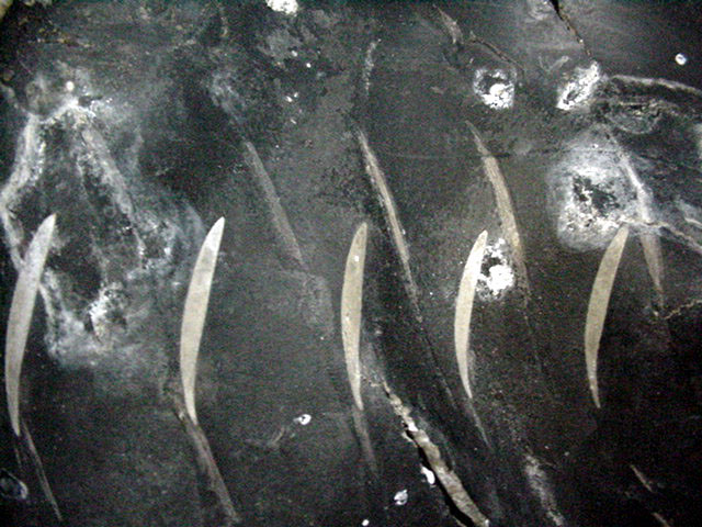
The inner fan housing exhibited distinct impression marks in the fan impeller blade tip path.

All of the fan impeller blades had broken away from the hub. The hub was deformed and the hub retention bolt was bent and fractured.
Determination
The location of the fan was determined by its description in the MD-11 Maintenance Manual (Company Edition).
The impression marks exhibited on the inner fan housing are consistent with contact with the tips of the fan impeller blade. The lack of rotational smears is consistent with marks being made by a stationary blade. The damage to the hub retention bolt was consistent with a bending overload failure, with no evidence of torsional loading. The damage is consistent with the fan not operating at the time of impact.
Avionics venturi valve
Description
The avionics venturi valve is located on the left side wall of the avionics compartment at fuselage STA 445. The valve shuts off the avionics exhaust airflow to prevent it from going overboard. The valve is normally in the OPEN position in flight. It can, however, be switched to the CLOSED position automatically by the ESC when the cabin airflow is too low for cabin pressurization, or manually by selecting the DITCHING switch or pushing the AVNCS FAN OVRD P/B.
Examination
The venturi valve was recovered without its electrical actuator. The valve body was flattened and the valve plate was retained within the body and aligned in a position that would indicate that it was in the OPEN position.

There were no marks on the interior valve wall or on the exterior of the valve near the valve override lever.

A light, soot-like coloured deposit was noted on the interior walls of both the avionics venturi and the avionics venturi valve.
Determination
The lack of marks on the interior valve wall or on the exterior of the valve near the valve override lever is consistent with the valve plate being in the OPEN position at the time of impact.
Aft tunnel venturi valve
Description
The aft tunnel venturi is located at fuselage STA 1880. The venturi expels air from the right aft tunnel area below the cabin floor and from the right side of the waste tank compartment into the atmosphere. The aft tunnel venturi valve controls the operation of the venturi and is normally in the OPEN position in flight.
Both the aft tunnel venturi valve and the avionics venturi valve receive their electrical commands and power from the ESC and the avionics venturi system control CB B1-1351. When the aft tunnel and the avionics venturi valves are commanded CLOSED, the avionics cooling control relay R2-5241 is energized, and the avionics compartment exhaust fan is commanded ON.
Examination
The aft tunnel venturi valve and actuator were recovered as a unit. The valve body was distorted and the valve plate and manual override lever were captured in a position approximately 30 degrees beyond the CLOSED position.
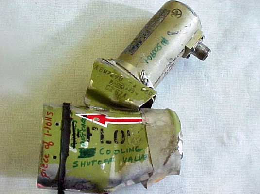
There were marks on the interior valve wall in the CLOSED position and on the exterior of the valve near the override lever. There were no other marks on the interior valve wall. There was a tar-like substance on the interior of the valve wall, downstream of the valve plate, covering an area of approximately 180 degrees around the wall surface. Although the source of the substance could not be confirmed, it appeared to match a substance used to seal the venturi valve to the venturi valve plate.

Determination
The marks on the interior valve wall and on the exterior of the valve near the override lever are consistent with the valve being in the CLOSED position at the time of impact and being driven to its captured position at the point of impact. The lack of marks on the interior valve wall is consistent with the valve plate being in the CLOSED position at the time of impact.
Finding the aft tunnel venturi valve in the CLOSED position was unexpected. Since the aft tunnel venturi valve and the avionics venturi valve both receive their electrical commands and power from the same source and it was determined that the aft tunnel venturi valve was in the CLOSED position at the time of impact, the avionics venturi valve should also have been in the CLOSED position.
The determination that the avionics compartment exhaust fan was not operating at the time of impact is consistent with the avionics venturi valve being in the OPEN position. Although the CLOSED position of the aft tunnel venturi valve could have resulted from the selection of the DITCHING switch, no other items operated by the DITCHING switch were determined to be activated at the time of impact.
The aft tunnel and avionics venturi valves were examined on another Swissair MD-11 aircraft, HB-IWA, during the aircraft's second "D check" on 7 November 2000. The aft tunnel venturi valve was in the CLOSED position and the avionics venturi valve was in the OPEN position, the same condition that existed on HB-IWF (the occurrence aircraft). According to SR Technics and Boeing, the aft tunnel venturi valve was installed by SR Technics under a service bulletin issued by Boeing. During their inspection of HB-IWA, SR Technics discovered that the pin wiring in the electrical connection for the aft venturi valve had been reversed during installation. SR Technics subsequently conducted a fleet inspection of their remaining MD-11 aircraft and found no further anomalies with the aft tunnel venturi valve. It is suspected that the same mis-wiring occurred on HB-IWF.
Avionics rack cooling fans
Description
There are two avionics rack cooling fans located in the avionics compartment at fuselage STAs 297 and 303.
Examination
Only minor pieces of the cooling fans were recovered and identified.
Determination
An assessment of the operational state of the fans at the time of impact could not be made based on the recovered pieces.
Forward cargo compartment ventilation fan
Description
The forward cargo compartment ventilation fan is located below the cabin floor in the right utility tunnel of the forward cargo compartment at fuselage STA 695. The fan moves air from below the floor of the forward cargo compartment through a hinged ventilation check-valve into the forward cargo compartment near the ceiling area, which is directly in line with the forward cargo compartment smoke and heat detectors. The fan is turned on when the forward cargo compartment temperature selector is turned on. It is designed to operate continuously under normal operations. The MSC will shut the fan off upon activation of a forward cargo smoke or fire detector.
The fan operates at 900 CFM. It is an electrically operated, 115 V AC three-phase fan. The fan is powered by the 115 V AC Bus 3 through CBs B1-1638, B1-1639, and B1-1640 on the right forward cabin CB panel. The 115 V AC Bus 3 is connected to the forward cargo compartment ventilation fan through relay R2-78, which is also on the right forward cabin CB panel. The relay is powered by the 28 V DC Bus 1 through CB B1-239 at position P18 on the upper main CB panel. The relay is controlled automatically by the MSC and must be energized to operate the fan. The relay can be de-energized manually to shut off the fan by pushing the FWD FLOW P/B on the cargo fire panel.
Examination
The fan housing was recovered as a single unit. It was identified by tag as Preco PN 23-26776, SN FA601221.
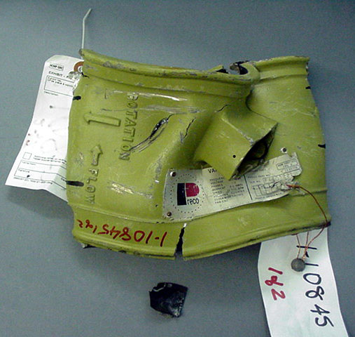
The fan housing was flattened. One fan impeller blade was trapped inside the flattened housing.

The fan housing exhibited a series of blade tip profile marks around the inner circumference of the fan. The marks were highlighted by an absence of paint on the housing. Another set of blade tip profile marks ran parallel to the fan stator blades.
The fan impeller blade exhibited no rotational damage or scratches on the leading edge or on the tip of the blade.

The electrical motor was not recovered.
Determination
The location of the fan was determined by its description in the MD-11 IPC.
Based on the location of the blade tip profile marks around the inner circumference of the fan, it was determined that the marks were made in the painted surface by the tips of the fan impeller blade while they were stationary. The lack of rotational marks on the leading edge or on the tip of the fan impeller blade is also consistent with the fan not operating at the time of impact.
The determination that the fan was not operating could have resulted from one of the following conditions:
- The fan was not receiving electrical power.
- The fan was responding to an input from the MSC as a result of activation of a forward cargo smoke or fire detector.
- The fan was responding to a crew selection of the FWD FLOW P/B on the cargo fire panel.
Both the 115 V AC Bus 3 fan CBs and the 28 V DC Bus 1 that supply power to the fan are mounted on the right forward cabin equipment panel, in an area of heat and fire damage. The fan relay control power wire runs through an area of heat from the relay to CB B1-239, located on the upper main CB panel. A loss of power to the relay or the thermal tripping of the CBs resulting from fire damage could account for the shutdown of the fan.
The cargo compartment floor area, the source of the fan's air supply, is connected by the cargo compartment sidewalls to the left and right tunnel areas. Air from the forward avionics compartment, which was determined to have contained smoke (as evidenced by the contamination of the avionics compartment radio rack air filter), is discharged either into the left tunnel area or overboard through the avionics venturi valve. Based on the determination that the avionics venturi valve was in the OPEN position at the time of impact, most, if not all, of the smoke-filled discharge air from the avionics compartment should have been directed overboard through the venturi valve. If some of the smoke-filled air were to be directed to the tunnel areas (i.e., past the check valve in the avionics compartment exhaust duct, or as a result of a breach in the Galley 3 chiller input duct drawing smoke from above Galley 3 down the right side and into the left right tunnel area), then smoke could have been drawn into the forward cargo ventilation fan intake area below the cargo floor and discharged directly at the forward compartment smoke and heat detector. Activation of the smoke or heat detector could also account for the shutdown of the fan.
Crew selection of the FWD FLOW P/B on the cargo fire panel cannot be ruled out. Regardless of crew action, however, the fan would have likely shut down owing to the heat or smoke generated by the fire.
Aft cargo compartment ventilation fan
Description
The aft cargo compartment ventilation fan is located below the aft cargo compartment floor at fuselage STA 1921. The fan moves air from below the floor of the aft cargo compartment, through a Y-shaped pipe, and past two hinged ventilation check valves, into the aft cargo compartment along the left and right outside walls. The fan is activated when the aft cargo compartment temperature selector is turned to the ON position. It is designed to operate continuously under normal operations. The MSC will shut the fan off upon activation of an aft cargo smoke or fire detector.
The fan operates at 300 CFM. It is an electrically operated, 115 V AC three-phase fan. The fan is powered by the 115 V AC Bus 1 through CBs B1-1641, B1-1642, and B1-1643 on the right forward cabin CB panel. The 115 V AC Bus 1 is connected to the aft compartment ventilation fan through relay R2-5678. The R2-5678 is powered by the 28 V DC Bus 3 through CB B1-243 at position S18 on the upper main CB panel. The relay is controlled automatically by the MSC and must be energized to operate the fan. The relay can be de-energized manually to shut off the fan by pushing the AFT FLOW P/B on the cargo fire panel.
Examination
The fan was attached to a section of the lower aft fuselage. It was identified by tag as Able Corporation PN 29480, SN 0008.
The fan housing was severely corroded as a result of its immersion in salt water; in some areas, the housing was completely corroded through.
The interior of the fan housing adjacent to the running path of the fan blades was also severely corroded. One area where the surface coating remained, however, exhibited minor rotational scratches.

The fan impeller was intact and the fan blades exhibited no leading edge or impact damage.
Determination
The location of the fan was determined by its description in the MD-11 Maintenance Manual (Company Edition).
It was determined that the minor rotational scratches on the fan housing resulted from contact with the tips of the fan impeller blade. The marks are consistent with the fan impeller rotating at the time of impact. Owing to the severe corrosion, however, an assessment of the operational state of the fan at the time of impact could not be made.
Cabin individual air fan
Description
The cabin individual air fan is located at STA 990 Y axis (–24 X axis). The fan supplies ceiling air to the individual seat air outlets; it does not provide air to the conditioned air system. The individual air fan is powered by the 115 V AC 3 right mid-cabin bus through CBs B1-324, B1-325, and B1-326. It is controlled through relay R2-198 in the right mid-equipment panel. Relay R2-198 is powered by the 115 V AC 3-phase A CB B1-1956 in the upper main CB panel at position N-08. The R2-198 is controlled through the Galley 3 slave relay. Relay R2-198 would be shut down as a result of a loss of Galley 3 power, the selection of the CABIN BUS switch, or the selection of the SMOKE ELEC/AIR selector to the 3/1 OFF position.
Examination
Four unidentified fans were recovered. None of the fans could be identified as the individual air fan or a recirculation fan, nor could they be matched to a particular location.
Determination
As none of the fans could be positively identified, no determination could be made for this fan.
Cabin air recirculation fans
Description
The aircraft is equipped with four identical cabin air recirculation fans and one cabin individual air fan. The cabin air recirculation fans are numbered 1 through 4 and are installed at the following locations:
| Fan | Y Axis | Z Axis | X Axis |
|---|---|---|---|
| Fan 1 | STA 685 | 100 | 28 |
| Fan 2 | STA 725 | 100 | 28 |
| Fan 3 | STA 1009 | 100 | 28 |
| Fan 4 | STA 1109 | 100 | 28 |
Fans 1 and 3 are powered by the 115 V AC Bus 1 and fans 2 and 4 are powered by the 115 V AC Bus 3. The fans are controlled by relays that receive power through the ESC. Galleys 1 and 3 master and slave relays must be powered in order for the fan relays to be energized. Galley 1 master and slave relays control fans 1 and 3 and Galley 3 master and slave relays control fans 2 and 4.
The cabin air recirculation fans are designed to be shut down by
- selecting the CABIN BUS switch;
- selecting the ECON switch;
- selecting the SMOKE ELEC/AIR selector;
- the ESC in response to a demand for lower cabin temperature; and
- de-energizing galleys 1 and 3 master and slave relays in response to a generator overload.
Examination and determination
Four of the five fans were recovered. None of the recovered fans could be identified as either a recirculation fan or the individual air fan, nor could they be matched to a particular location.
Recovered fan exhibit 1-2467
Exhibit 1-2467 examination
This fan was recovered as a single unit. It was identified by the MD-11 IPC as PN 605457-8.

Etched into the housing body was PN 605138-3 R (code ident) 70201. The hub of the composite centrifugal impeller was attached to the motor. The impeller blades and outer periphery of the impeller, however, had broken away. The flanged end of the motor housing assembly had also broken away. Deep rotational gouge marks were noted in two locations on the underside of the impeller. One gouge mark aligned with the outer periphery of the broken flange and the other mark aligned with the broken edge of the motor housing.

The top of the motor housing also exhibited rotational scratches.
The armature and stator exhibited extensive corrosion and were contaminated with silt deposits. Minor rotational marks were exhibited in areas where corrosion was less visible.
Exhibit 1-2467 determination
It was determined that the rotational scratches on the top of the motor housing resulted from contact with the underside of the impeller. It was not determined, however, whether the marks on the armature and stator marks resulted from the impact. The rotational marks on the impeller and motor housing are consistent with the fan operating at the time of impact.
Recovered fan exhibit 1-9196
Exhibit 1-9196 examination
This fan was recovered as a single unit. It was identified by the MD-11 IPC as PN 605457-8. The hub of the composite centrifugal impeller was attached to the motor. The impeller blades and outer periphery of the impeller had broken away. Approximately 50% of the flanged end of the motor housing assembly was not recovered.

The underside of the impeller exhibited a pattern of gouge marks and rotational marks.


Rotational scratches were also noted on the top of the motor housing.

Exhibit 1-9196 determination
It was determined that the rotational gouge marks on the underside of the impeller resulted from contact with the broken motor housing flange. The rotational marks on the impeller and motor housing are consistent with the fan operating at the time of impact.
Recovered fan exhibit 1-11297
Exhibit 1-11297 examination
This fan was recovered as a single unit. It was identified by the MD-11 IPC as PN 605457-8. The hub of the composite centrifugal impeller was attached to the motor. The impeller blades, the outer periphery of the impeller, and the entire flanged end of the motor housing assembly had broken away.

Three pieces of detached impeller blades were identified as part of the impeller hub; one was marked as Exhibit 1-11297.

A faint, arc-shaped mark was noted on the underside of one of the detached pieces that matched the location and pattern of the rotational gouges exhibited on two of the other fan impellers.


Exhibit 1-11297 determination
It was determined that the faint, arc-shaped mark on the underside of one of the detached pieces resulted from contact with the motor housing flange. Due to the faintness of the mark, it could not be determined whether the mark resulted from rotation or from bending failure of the flange.
Recovered fan exhibit 1-8212
Exhibit 1-8212 examination
This fan was recovered as a single unit. It was identified by the MD-11 IPC as PN 605457-8. The hub of the composite centrifugal impeller was attached to the motor. The impeller blades, the outer periphery of the impeller, and the entire flanged end of the motor housing assembly had broken away.

A deep, arc-shaped gouge was noted on the underside of the impeller that aligned with the broken edge of the fan housing.
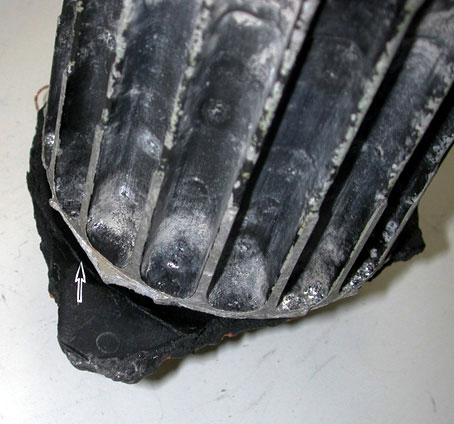

Exhibit 1-8212 determination
The gouge on the underside of the impeller was similar to the gouge noted on Exhibit 1-2467, which was assessed as operating at the time of impact.
Two of the four unidentified recovered fans exhibited rotational gouges and marks consistent with the fans operating at the time of impact. The two remaining fans exhibited similar, but fainter, marks. The operation of these fans could not be determined. As the fans' power source is paired and two of the fans were operating at the time of impact, it was determined that either the 115 V AC Bus 1, or the 115 V AC Bus 3, or both were powered at the time of impact. As the exact numbered location of the fans is unknown, their corresponding power source could not be determined.
Aft tunnel cooling fan
Description
The aft tunnel cooling fan draws air from the cabin area and discharges it into the aft right tunnel. The fan is powered by the 115 V AC ground service bus and is designed to operate only on the ground.
Examination
The fan was recovered largely intact as a single unit, but it exhibited severe corrosion as a result of its immersion in salt water.

The fan was identified by tag as Able Corporation PN 29490, SN 30. Its location was determined by its description in the MD-11 IPC, Section 21-24-07. A delaminated piece of interior wall or floor honeycomb structure was wedged between the tip of the leading edge of the fan blades and the outer housing. The outer housing wall exhibited minor rotational scuff marks in the area of the blade tip path.


Determination
Because the fan is only powered on the ground, it was determined that the minor rotational damage was likely the result of the fan being rotated upon impact by the ingestion of water and debris.