Supporting technical information A98H0003
Associated links (A98H0003)
-
Table of contents
Oxygen systems
Passenger oxygen
Description
The passenger oxygen system installed on HB-IWF consisted of 148 independently mounted chemical oxygen generators. The generators were manufactured by Scott Aviation (Scott) and consisted of 47 two-person generators (PN 801386, Series -82), 81 three-person generators (PN 801386, Series -83) and 20 four-person generators (PN 801386, Series -84).
The chemical generators and oxygen masks were mounted in oxygen box assemblies in the overhead stowage locations in the passenger cabin, the attendants' consoles, and the lavatories in the following numbers:
| Location | Type of Generator | ||
|---|---|---|---|
| Two-Person | Three-Person | Four-Person | |
| Passenger cabin | 16 | 81 | 20 |
| Lavatories | 9 | ||
| Flight attendant station | 12 | ||
| Skybunk area | 3 | ||
| Crew rest area | 7 | ||
Each oxygen box contains one chemical oxygen generator that supplies oxygen to two, three, or four passengers for a minimum of 15 minutes.
Module doors provide access to the oxygen masks and generators. The doors are held closed by electrically operated bayonet latches that release when energized. The doors are automatically opened through an aneroid switch if the cabin pressure climbs above approximately 14 400 feet. If the doors fail to open automatically, a NO MASKS warning light on the air system panel in the cockpit will illuminate. The flight crew can select the doors open by pressing the NO MASKS push button on the air system panel. The doors can be opened manually, for maintenance purposes, by pressing on the latch lever with a sharp probe.
Once an oxygen generator has activated, the thermal decomposition of the generator core continues until the core is consumed. Each passenger oxygen mask is fitted with a reservoir bag that is attached to the oxygen generator with a flexible hose. When a generator is initiated, the reservoir bag unfolds and may inflate (depending on the altitude) until breathing begins.
Oxygen generators
The Scott series 801386 oxygen generator cores are housed within a nickel shield and a stainless steel case. The three- and four-person generators are fitted with an additional internal copper shield. Once activated, the nickel shield will quickly discolour from exposure to heat. The cylindrical core in all models is insulated with a granular and pad-type insulation in order to maintain the external case temperature below the normal operating temperature of approximately 500°F.
The oxygen generators are actuated by pulling a lanyard pin, which releases a spring-driven striker against a percussion cap. A pull force of from 1 to 6 1/2 lb is required to disengage the lanyard. The generators burn a mixture of sodium chlorate and iron to produce oxygen and are designed to produce an increased flow of oxygen near the beginning of the burn sequence. During the 15 minutes of decomposition, the two-person oxygen generator will produce a minimum of 42 L of oxygen, the three-person generator will produce a minimum of 62 L of oxygen, and the four-person generator will produce a minimum of 84 L of oxygen. The maximum operating pressure is 40 psig for the first 30 seconds of activation and 35 psig for the duration of the burn.
An oxygen generator may also be activated by exposure to heat. According to the manufacturer, the core material has to reach 700°F before activation takes place. For example, if the generator was placed in an oven at 700°F, it could take up to an hour for an auto-reaction to take place.
The generators have a calendar life of 12 years. These generators are not fitted with an external indicator to identify whether the generator has been activated, and are considered unserviceable if the percussion cap has been struck by the hammer and the percussion cap is dented.
Electrical circuitry to release module door latches
Power to release the door latches is provided through primary and secondary relays. The secondary relay is automatically activated after a short delay. Power to the primary relay is provided by the 28 V DC Generator Bus 3 through CB "PASS OXY CTL PRI" located in the upper main CB panel at Row K-04. The secondary relay is powered by the 28 V DC Generator Bus 1 through CB "CREW OXY QTY IND/PASS OXY CTL SEC" located in the upper main CB panel at Row J-05. The door latches in turn are powered from 115 V AC generator buses 2 and 3 (phase A). Activation of the aneroid switch completes a circuit to ground for the "PASS OXY EJECT CTL" relay powered from the 28 V DC Generator Bus 1 through CB "PASS OXY CTL MASTER" located on the upper avionics CB panel at C-04.
Examination
The 118 recovered oxygen generators had all sustained moderate to severe impact damage, and none retained the lanyard pin. The core material in several ruptured generators had been flushed as a result of water immersion. None of the recovered oxygen generators displayed evidence of exposure to external heat or soot. One generator was recovered in a green oxygen box. The outer surface of this box appeared to be sooted. Although the percussion cap was fired, the generator had not activated.
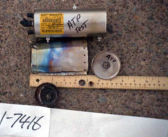
Scott Aviation provided five 801386-series oxygen generators for comparative analysis. These generators were activated (as follows) and cut open to allow examination of the shield(s).
- Test Sample 1 was a new three-person generator that had not been fired. All of the components were in a new, bright condition.
- Test Sample 2 was a three-person generator that had been discharged under 15 cm of fresh water. Less than 6 cm of the 14 cm nickel shield was discoloured as a result of heat stress, and the copper shield was bright. The generators had to be held under water for these tests or they would have floated.
- Test Sample 3 was a three-person generator that had been fired and discharged in a normal air environment. Almost the entire length of the 14 cm nickel shield was discoloured as a result of heat stress, and the copper shield was dulled.
- Test Sample 4 was a two-person generator that had been fired and discharged in a normal air environment. Approximately 10 cm of the 13 cm nickel shield was discoloured as a result of heat stress.
- Test Sample 5 was a two-person generator that had been discharged under 15 cm of fresh water. Less than 4 cm of the nickel heat shield was discoloured as a result of heat stress.
Test Sample images:
The following criteria were used to evaluate whether the percussion cap been had fired and whether the core had initiated:
- The end of the percussion cap was examined for evidence of a hammer strike. Typically, the hammer strike leaves a dent in the centre of the cap. Caps that had been struck were visually examined for evidence of an atypical strike consisting of a shallow, off-centre, or double hammer strike. An atypical strike would likely be a result of impact with the water, after the hammer's hinge bracket had been squeezed or bent.
- The percussion cap tube was examined for evidence of discolouration and corrosion. The absence of either discolouration or corrosion at the tube would be evidence that the percussion cap had not fired.
- The dome at the head end of the core was visually examined for light grey "flash" material, the presence of which would be evidence that the flash material had not been initiated.
- The dome at the head end of the core was visually examined for evidence of heat stress. The presence of heat discolouration would be evidence that the cap had fired and the core had initiated.
- The wall of the nickel shield was examined for discolouration (blueing) from heat stress. The presence of blueing would indicate that the core had initiated and thermally decomposed. The length of the discoloured area of the wall was compared to samples provided by Scott Aviation to determine whether the generator had decomposed in an air or a water environment.
Of the 118 recovered oxygen generators, 83 were dismantled to allow the nickel shields on the two-person generators, and the nickel and copper shields on the three-person generators to be compared to the test samples. Based on the above criteria, 55 generators had initiated and likely decomposed underwater; 28 generators had not initiated, although the percussion caps of 10 of these had fired.
The shields of the 55 generators that had initiated all resembled those of the exemplars that were activated and immediately placed under water.
Determination
Except for the one oxygen box that appeared to have been sooted, there was no evidence on the 118 recovered generators to show that they were exposed to an external heat source or had contributed to the on-board fire.
Based on the oxygen generator examination, approximately 66% were activated by the percussion cap, while the remaining ones failed to activate. This would be an extremely low percentage for activation, had the generators been deployed in flight by the crew. It is assumed that if the masks had been dropped, the passengers would have used them. There was no evidence from the CVR recording to suggest that the passenger oxygen system was activated during the descent from 33 000 feet.
Those oxygen generators that were decomposed were considered to have been activated as a result of impact forces, when the oxygen generators disengaged from the lanyard-mounted striker retaining pins.
Crew oxygen
Examination
Oxygen supply lines
Because of the routing of the crew oxygen supply lines through a fire-damaged area above the cockpit ceiling, the oxygen lines were examined to see whether a breach in the lines could have contributed to the propagation of the on-board fire. The following oxygen lines were recovered and examined:
Exhibit 1-12554 is a 13-inch long section of tubing (3/8-inch OD, 0.016-inch thick). This tube was flattened over 8 inches and had an overall soot-like appearance. This exhibit came from Exhibit 1-9954. One inch from an end were the remains of a thermoclad insulating red material used on the oxygen tubing. Both ends of the tube were fractured. The exhibit was identified as CRES 21-6-9 steel.
Exhibit 1-12546 is a 24.5-inch long section of tubing (3/8-inch OD, 0.016-inch thick). The remains of a red enamel coating thermoclad insulating material were located in various places along the tube. Both ends were fractured. One inch from one fractured end was an S492449-6S union. This type of union is used in three locations in the 3/8-inch OD tubing running from the oxygen bottle to the transition to 1/4-inch OD tubing, just to the right of the aircraft centreline, in the cockpit, between STA 383 and STA 374. There was no evidence of any heat distress on this tube.
Exhibit 1-12547 is a 14-inch long section of tubing (3/8-inch OD, 0.016-inch thick). Remains of a reddish paint was observed over the tubing surface. It was noted that the paint could be easily scraped off with a finger nail. Both ends were fractured. The remains of a green oxygen tag were located approximately one inch from a fractured end. There was no evidence of any heat distress on this tube.
Exhibit 1-12548 is a 34.5-inch long section of tubing (3/8-inch OD, 0.016-inch thick). Both ends were fractured. A union 6 1/4 inch from one end joined two pieces of tube. The tube had red enamel paint remaining in numerous places along the length of the tube. This tube was originally attached to an instrument air tube located in the avionics compartment. There was no evidence of any heat distress on this tube.
Exhibit 1-12550 is a 22-inch long section of tubing (1/4-inch OD, 0.016-inch thick). Both ends were fractured. The tube had red enamel paint remaining on it, from end to end. There was no evidence of any heat distress on this tube.
Exhibit 1-7747 is a 10¾-inch long section of tubing (1/4-inch OD, 0.016-inch thick). This tube had red enamel paint on it. There was no evidence of any heat distress on this tube.
Exhibit 1-12549 (from 1-9954) is a 4 1/2-inch long section of tubing (1/4-inch OD, 0.016-inch thick). Both ends were fractured. This tube had red enamel paint on it. There was no evidence of any heat distress on this tube.
Exhibit 1-7748 is a 17-inch long section of tubing (5/16-inch OD, 0.035-inch thick). The tubing had the green primer on it and the remains of a tag. The tag had the following on it: "Breathing Oxygen," "Crew Oxygen," and the PN ABM7005-615. There was no evidence of any heat distress on this tube. The tube was determined to have been attached to the oxygen cylinder located in the avionics compartment.
Exhibit 1-11822 is a 6 3/4-inch long section of tubing (1/4-inch OD, 0.016-inch thick). Both ends were fractured. The remains of a tag were affixed to the tube, with "Breathing Oxygen" written on it. The red enamel paint, which appeared under the tag, could be peeled off the tube easily. The remainder of the tube was bare of any paint. This 1/4-inch line had been located in the avionics compartment and down the right side of the aircraft.
Oxygen cylinder
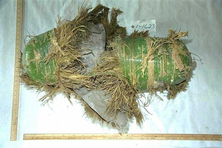
The oxygen cylinder was examined visually and physically. The internal metal shell had been ripped apart and was held together by the para-aramid fiber jacket only. To assist examination of the fracture surfaces, the para-aramid fiber jacket was removed from one half of the metal shell.
The fracture path observed on the interior shell was predominantly circumferential, with a pronounced shear lip. The shell was considerably deformed (flattened). The deformation and the orientation of the fracture path was similar to that from containers that were tested to failure. The most likely failure scenario was a rupture, caused by a sudden reduction in volume, from crushing, and the resulting pressure build up. The physical features of the ruptured shell were consistent with the failure of the cylinder under pressure.
Portable oxygen
Description
First aid and cabin crew oxygen was stored in twelve 310 L oxygen cylinders, located at various points in the passenger cabin. Four 120 L portable oxygen cylinders, with masks, were also stowed in the passenger cabin.
Examination
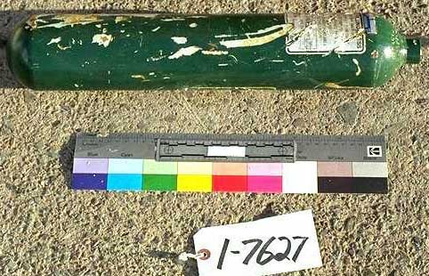
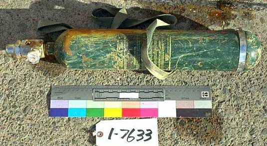
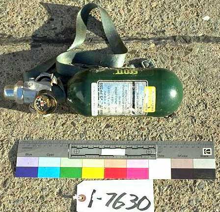
Three (of four) 120 L portable oxygen cylinders were recovered, as were eight (of twelve) 310 L cylinders. Visual examination revealed no evidence of heat damage.
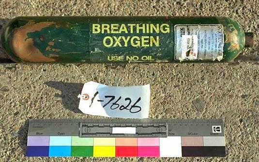
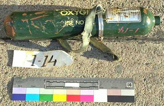
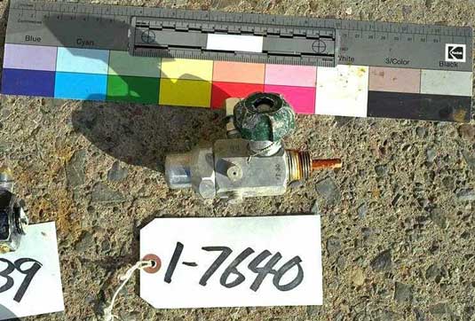
The following information was collected during visual examination of the recovered oxygen cylinders:
- 310 L (11 cubic feet) Scott portable.
Regulator detached, cylinder wall dented, contains sea water. Threaded portion of fractured regulator nipple retained in cylinder neck. Swissair control tag 9700CIA. Weight 2 435 grams. Stamps on shoulder: 3AA-1800, C02454P, 12-80+*. - 310 L (11 cubic feet) Scott portable.
Regulator detached, one dent in sidewall. Threaded portion of fractured regulator nipple retained in cylinder neck. Strap attached, one end secured with band clamp. PN ??BF23B,Footnote 1 manufacturing date 7/87, 0B50087-36, hydro date 3/87+*. Weight 2370 grams. Stamps on shoulder: DOT-3AA-1800, L 586575 Pst. - 310 L (11 cubic feet) Scott portable.
Regulator detached, small dent in wall near bottom. Threaded portion of fractured regulator nipple retained in cylinder neck. Swissair tag IDN 7.08810, ASN 0.385, PN 9700-??3523P, Scott model ?970 series, Boeing 87/??, manufacturing date ?0/03, hydro date 8/93+*. Weight 2285 grams. Stamps on shoulder: DOT-3AA-1800, 397971 Pst. - 310 L (11 cubic feet) Scott portable.
Regulator detached, one dent near bottom. Threaded portion of fractured regulator nipple retained in cylinder neck. Swissair tag IDN 7.08810, ASN not legible, PN 9700-C1A-?, Boeing PN 60B50087, manufacturing date 10/93, hydro date 8/93+*. Weight 2 315 grams. Canadian Forces partial conditioning tag duct-taped to cylinder (post-recovery). Stamps on shoulder: DOT-3AA-1800, C397969 Pst. - 310 L (11 cubic feet) Scott portable.
Regulator attached, on-off control knob detached, thread end of cylinder damaged. Valve in closed position. Small piece of magnetic material on cylinder wall. Cylinder discharged, contained sea water, regulator removed and sea water emptied. Hydro date 9/92+* (stamped on shoulder). Weight 3 050 grams (after dumping sea water). Stamps on shoulder: DOT-3AA-1800, C46376 Pst, 2(A2)(21)98. - 310 L (11 cubic feet) Scott portable.
Regulator attached, valve bent, on-off knob detached, four ports exposed on head, minor damage to cylinder. Valve in open position. Strap secured to bottom of cylinder with clamp. Cylinder empty. Hydro date 5/90+* (stamped on shoulder). Weight 3 120 grams. Stamps on shoulder: DOT-3AA-1800, 026527 Pst. - 310 L (11 cubic feet) Scott portable.
Regulator attached and damaged, three valve ports open. Swissair tag 9700C1ABF23B, Swissair tag IDN 708810, ASN 0179. Valve closed, cylinder empty. Piece of Canadian Forces material condition tag attached, torn portion of tag says "empty"(may have been discharged for safety reasons). Weight 2 600 grams. Stamps on shoulder: DOT-3AA-1800, 9.92, 94456DN, AWK, AUERSTOFF, Swissair, 9 SR 97*, 02026, 1212K70+, LG.2.07kg.FD.127BAR, V.2.53LT.PD.211BAR. - 310 L (11 cubic feet) Scott portable.
Regulator attached, gauge detached, two ports open owing to damage, cylinder dented near bottom of wall. Valve closed, contained sea water, regulator removed and sea water dumped. Swissair tag 970021A5F20B, PN 9700-C1A-F20D. Weight 3 280 grams. Stamps on shoulder: ICC-3AA2100, K-1932, SCOTT, 8 (B9) (04), 89*06, 60194, 11(cam)78, 12056*, 2 66, 5664. - 120 L (4.25 cubic feet) Scott portable.
Regulator detached, one large dent in wall near neck. Threaded portion of fractured regulator nipple retained in cylinder neck. Decal "For Crew Use Only." Hydro date 12/91+* (stamp). Weight 1 360 grams. Stamps on shoulder: DOT-3AA-1800, C151649 Pst. - 120 L (4.25 cubic feet) Scott portable.
Regulator attached, gauge attached, needle detached, strap attached. Valve in closed position. Cylinder displays no significant damage. Swissair control tag SK??6805, 9700-A1A-BF23BV-SR, PN 9?0-A1A-BF23B. Cylinder was still charged. Manufacturing date 8/90, hydro date 2/90+* (stamp). Weight 2 300 grams. Stamps on shoulder: DOT-3AA-1800, 960482 Pst. - 120 L (4.25 cubic feet) Scott portable.
Regulator attached, shaft for on-off control knob bent, strap attached to neck. Valve in closed position. Decal "For Crew Use Only." Valve/regulator damaged, cylinder shows no significant damage. Cylinder empty when examined; however, it may have been discharged by recovery personnel as a safety precaution. Swissair control tag SN 36814, 9700-A1A-BF23BV-SR, PN 9700-A1A?? Weight 2 195 grams. Stamps on shoulder: DOT-3AA-1800, 960556 Pst. - Detached Scott oxygen regulator.
Nipple fractured. PN 80H6010, SN 3229. On-off control knob detached, valved jammed, position unknown. - Detached Scott oxygen regulator.
On-off control knob attached. Valve in open position. Ink stamps A4Q93, PT30. - Detached Scott oxygen regulator.
Nipple fractured, PN 801160-03. Gauge attached, no needle. On-off control knob detached, valve jammed, position unknown. - Detached Scott oxygen regulator.
Nipple fractured, gauge detached, three ports open, on-off control knob detached, valve open. - Detached Scott oxygen regulator.
On-off knob attached, gauge detached, two ports open owing to damage. Regulator has been unthreaded from a cylinder. Valve in open position.
Images of the recovered oxygen cylinders:
Determination
Of the 16 portable oxygen cylinders, 11 were recovered. Unfortunately, during the initial recovery phase some of the oxygen cylinders may have been discharged as a safety precaution before they could be examined by TSB personnel. However, it is likely that at least three of the cylinders were still charged when recovered; another three had damaged regulators and were empty; the remaining five were missing their regulators. Of the five detached regulators that were recovered, three were in the open position and the position of the other two was unknown. One of the open detached regulators appeared to have been unscrewed from a cylinder and may have been opened by recovery personnel to discharge the cylinder. The two remaining open detached regulators had their on-off knobs broken away and likely were open at the time of impact.


