
Supporting technical information A98H0003
Associated links (A98H0003)
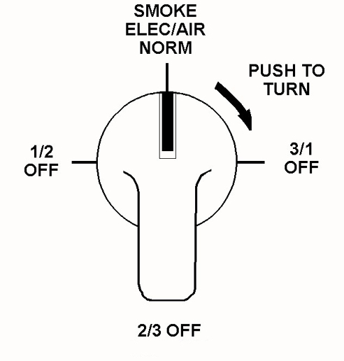
SMOKE ELEC/AIR Selector
SMOKE ELEC/AIR selector description
The SMOKE ELEC/AIR selector controls the electrical and air systems' isolation functions when the system is in auto or manual mode.
The switch is a rotary four-position push-to-turn design. The selector body consists of a four-gang stack of switch terminals identified as A, B, C, and D. The selector neck is threaded and designed with a slot to allow for the installation of a lock tab to align and position the selector in the panel. The threading of the neck allows for two nuts to be used (one on each side of the panel) to secure the selector to the panel. The shaft of the selector extends approximately half an inch beyond the threaded selector neck to allow for the installation of the selector knob. The shaft is designed with a machined flat (progressing through approximately one quarter of the diameter of the shaft) to allow for the alignment of the knob with the selector. The shaft flat is designed to face upward and aft when the selector is mounted in the panel and the knob is in the NORM position. The shaft is also designed with two additional machined undercut flats that progress from the centre outer circumference of the shaft to a Vee point opposite the flat (the Vee being at the 6 o'clock position when viewed directly from the back). The flats are undercut, in that they do not progress through to the end of the shaft as does the machined flat. The flats are designed such that two set screws, mounted in the knob, can be tightened against the shaft to secure the knob to the shaft.

SMOKE ELEC/AIR selector positions
The selector has four positions: NORM, 3/1 OFF, 2/3 OFF, and 1/2 OFF. It must be pushed in and turned clockwise to move to the next position.
| Position | Action |
|---|---|
| NORM | All generator relays, auxiliary power relays, bus tie relays, and DC tie remote control CBs are in the normal auto or manual mode. The air system operation is normal. |
| 3/1 OFF | Generator System 3 is de-powered. ECON mode and Galley Bus 3 is unpowered. EIS cathode ray tubes go full bright. Pack 1 and Air Supply 1 turn off. |
| 2/3 OFF | Generator System 3 is again powered, Generator System 2 is de-powered. Galley Bus 3 is again powered and Galley Bus 2 is
de-powered. Pack 1 and Air Supply 1 are reinstated. Pack 3 and Air Supply 3 are turned off. |
| 1/2 OFF | Generator System 2 is again powered, Generator System 1 is de-powered. Galley Bus 2 is again powered and Galley Bus 1 is
de-powered. Automatic transfer of emergency power is inhibited. Pack 3 and Air Supply 3 are reinstated. Pack 2 and Air Supply 2 are turned off. |
| NORM | Generator System 1 is again powered. The ECON capability of the air system returns and Galley Bus 1 returns to normal operation. EIS CRTs return to auto brightness control. Pack 2 and Air Supply 2 are reinstated. |
SMOKE ELEC/AIR selector examination
Some of the remains of the SMOKE ELEC/AIR selector were recovered and examined, including the threaded shaft neck, the two mounting nuts, the lock tab and washer arrangement, and the switch base plate. Two indentations were noted in the threaded shaft neck and an exemplar selector was requested from the manufacturer for comparison. (The exemplar selector was received from Honeywell and was exhibited as 1-12817. A label on the selector identified it as being manufactured by Janco Corporation in Burbank, California, and rated at 5 A 115 V AC. The number 51-2006 (8743) was stamped on the body of the selector.)
The four-gang stack of selector terminals and the shaft had pulled free from the shaft neck and selector base plate and were not recovered. The selector base plate was bent and the two selector plate lug holes were torn open. The lip of the threaded shaft neck, when viewed directly from the back, had two gouge marks, one at the 3 o'clock and one at the 6 o'clock position, and had a rolled edge area between the 7 o'clock and 8 o'clock position.


SMOKE ELEC/AIR selector determination
The damage to the selector base plate and the two selector plate lug holes is consistent with the selector being subjected to a side load on the base of the selector. The rolled area on the lip of the threaded shaft neck is consistent with the shaft contacting the inner bore of the neck from the side or bending load placed on the selector. The two gouge marks matched the locations and dimensions of the corners of the machined undercut flats in the shaft. The Vee area of the shaft aligned with the gouge at the 6 o'clock position or with the knob in the NORM position. It was determined that the selector was in the NORM position at the time of impact.
Influence of SMOKE ELEC/AIR selector position on fuel dumping
Fuel dump initiated and SMOKE ELEC/AIR selector selected to 3/1 OFF position
Fuel dumping is initiated through the FUEL DUMP switch on the fuel control panel located in the overhead switch panel. Activation of the switch turns on the fuel boost and transfer pumps and opens the cross-feed and dump valves, allowing fuel to dump equally through the left and right fuel dump valves. If the SMOKE ELEC/AIR selector is selected to the 3/1 OFF position (shutting down Generator 3 and the right emergency bus), the Tank 1 aft boost, Tank 2 transfer, Tank 2 left aft, Tank 3 forward boost, and the lower auxiliary right transfer pumps turn off and fuel dumping continues at a slightly lower discharge rate.
SMOKE ELEC/AIR selector in 3/1 OFF Position and fuel dump stopped
If the FUEL DUMP switch is shut off with the selector in the 3/1 OFF position, the right dump valve and the Cross-Feed Valve 3 will not close, as they require power from Generator 3. In order to prevent further loss of fuel from Tank 3, the two remaining operating pumps (Tank 3 aft boost and Tank 3 transfer pumps) must be turned off. This results in Engine 3 being on suction feed.
If the fuel dump is stopped but the right dump valve is not closed and the Tank 3 pumps are not turned off, fuel will continue to be dumped from the right side at approximately 1 000 lb/min. A "DUMP VLV R DISAG" level 2 alert, a "FUEL XFEED 3 DISAG" level 1 alert, and an illuminated Tank 3 cross-feed disagree light on the overhead panel will result. If these indications are not acted upon, a structural load imbalance limit of 4 000 lb may occur. If this limit is reached, a "LAT FUEL UNBAL" level 2 alert will be displayed. If still no action is taken, the fuel level in Tank 3 will drop enough to cause the fuel pumps on the SD to flicker between green and amber and eventually go full amber, resulting in a "TANK 3 FWD PMP LO" level 2 alert, a "TANK 3 PUMPS LO" level 2 alert, a "TNK FUEL QTY LO" alert and the illumination of Tank 3 pumps' low light on the overhead panel. If still no action is taken, Tank 3 will run out of fuel and Engine 3 will shut down.
SMOKE ELEC/AIR selector in 3/1 OFF position and fuel dump not stopped
If the fuel dump is not stopped, a "FUEL DUMP LEVEL" level 2 alert appears with the consequence "STOP FUEL DUMP." A level 3 alert "TNK FUEL QTY LO" with the consequence "STOP FUEL DUMP" appears with 8 000 to 9 000 lb of fuel remaining in Tank 3.
SMOKE ELEC/AIR selector in 3/1 OFF position and fuel dump started
If the fuel dump is started with the selector in the 3/1 OFF position, the right fuel dump valve and the Cross-Feed Valve 3 will not open. The alerts "DMP VLV R DISAG" and "FUEL XFEED 3 DISAG" will immediately appear. If no action is taken, after some time the structural lateral imbalance limits may be approached and the "LAT FUEL UNBAL" alert appears. If still no action is taken, the fuel level will become low enough that the low-level fuel dump shut-off system closes the three fuel cross-feed valves and the left fuel dump valve, terminating the fuel dump.
If the fuel dump was started after the SMOKE ELEC/AIR selector was positioned, the fuel dump is terminated at the low-level shut-off quantity, regardless of the position of the switch.
The fuel low-level shut-off circuits were revised to provide redundant power sources on fuselage 545 and subsequent fuselages. Fuselages prior to 545 could incorporate MD-11 SB 28-048. An AD in this regard was subsequently issued in May 1994 by the FAA. As a result of this revision, tanks 1 and 3 will shut off at their low-level quantity unless the SMOKE ELEC/AIR selector is in the 3/1 OFF or 1/2 OFF positions after the fuel dump has started. This prevents one of the dump valves from closing and prevents the tanks 1 or 3 cross-feed valves from closing. Flight crew intervention would be necessary to stop the flow of fuel out of the respective tanks.
If the Tank 2 cross-feed were open with the SMOKE ELEC/AIR selector in the 2/3 OFF position, it would continue to supply fuel to the dump valves. However, once the total usable fuel reaches 30 000 lb, the dump valves would automatically close and stop the fuel dump.
Potential use of SMOKE ELEC/AIR selector causing loss of recorders
Prior to the recorders stopping, the engine N2 values were steadily decreasing with the aircraft altitude around 10 300 feet. At 0125:40, approximately one second prior to the recorders stopping, the FDR recorded Engine 2 N2 at 6 049 rpm (61.1%) and Engine 3 N2 at 6 059 rpm (61.2%). The first faults (after the ST350X) written to FADEC 2 were N2 of 6 016 rpm (60.8%) and the first faults written to FADEC 3 were N2 of 6 016 rpm (60.8%). The closeness of the FDR N2 engine speeds and the FADEC-recorded N2 speeds make it appear that the faults written to the FADECs occurred shortly after the loss of the recorders.
The FDR is powered from 115 V AC Bus 3 and the CVR from the right emergency 115 V AC bus. Both buses in turn are powered from the main Generator Bus 3. Both recorders appeared to have stopped within 0.4 seconds of each other ± 1 second. The FADEC data was used to assess whether the SMOKE ELEC/AIR selector had been used by the crew. If the selector was used at 0125:41, Generator Bus 3 and all of its sub-buses would be de-powered. Of particular interest is that the Engine 3 probe heater, FCC-2, ADC-2, FADEC 3 28 V DC-3 backup power, and both recorders—all powered by Generator Bus 3—would be de-powered by this action at the same time and they were not.
During the time frame from 0125:06 to 0125:41 when the recorders went off-line, the FDR did not record any altitude and airspeed data. Air traffic services also did not record any ATC transponder altitude (Mode C) during this time frame, although the transponder identification code (Mode A) continued to be recorded. However, at 0125:49.6, altitude data was again recorded by ATC until 0126:04.1 reporting an altitude of 9 700 feet for all four recorded sweeps. It was Swissair's practice to use transponder ATC-1 on odd-numbered flights (SR 111), which obtains its primary air data from ADC-1. For ATC-1 to start sending Mode C altitude information either ADC-1 was recovered or the pilot had to switch the air data source to ADC-2. ADC-1 was powered from the left emergency 115 V AC bus. This bus was no longer powered because of an arcing event that occurred on that wire; therefore, the air data source had to have been switched to ADC-2 to recover ATC. This switching would have to take place within 8.5 seconds from the time the recorders went off-line to regain the Mode C. It was likely that the transponder, not the air data, was lost at 0126:04 as both mode A and C functions were lost.
Assuming the SMOKE ELEC/AIR selector was used at 0125:41 and caused the loss of the recorders and initiated the FADEC 2 and 3 faults, the ADC-2 fault would be written to NVM approximately 15 seconds later. This is based on the loss of FCC-2 taking 10 seconds to be written to NVM and then an additional 5 seconds for the FADEC to register the loss of ADC-2. These numbers are approximate as the faults are entered into a three-word buffer prior to being sent to NVM. Each word is written to NVM once per second; if more than one fault is written at a time it may take up to three seconds after the initial time delay to be entered into NVM. This means that ADC-2 would be off at 0125:58 and at least six seconds prior to this (0125:52) because the fault must be at least five seconds in duration before the FADEC writes it to NVM. Between 0125:49.6 and 0126:04.1, Mode C altitude was being recorded by ATC; therefore, ADC-2 had to have been operational. Therefore, the SMOKE ELEC/AIR selector was not turned to the 3/1 OFF position at 0125:41 and did not cause the loss of the recorders.
Potential Use of SMOKE ELEC/AIR selector after loss of recorders
The SMOKE ELEC/AIR selector was not believed to have been used at the time the recorders stopped. Because of the timing of two of the NVM faults from FADEC 3, the failure of particular systems, and the lack of a credible fire scenario to have caused these two faults, it was considered that the SMOKE ELEC/AIR selector was turned to the 3/1 OFF position at some time after the recorders were stopped. The selector could not have been turned before this time as the recorders would have stopped recording sooner. The first five faults after ST350X on FADEC 3, starting with the PHEATF to the RADCF, were all written at the same N2 of 6 016 rpm. The recorded altitudes varied from a high of 10 314 feet to 9 787 feet. However, given the tolerance of ± 470 feet, the recorded altitudes were most likely recorded around the 10 000-foot level. The ATS recorded altitude was 9 700 feet during the four sweeps that Mode C returned.
Using the SMOKE ELEC/AIR selector (3/1 OFF position) would cause FCC-2 and ADC-2 to shut down simultaneously. The loss of FCC-2 and ADC-2 were the third and fourth faults recorded on FADEC 2. However, the RADCF fault on FADEC 2 was recorded at a higher N2 (6 656 rpm) than the FCCF (6 016 rpm) fault on FADEC 3. At this time FADEC 3 would have switched to the alternate N1 mode; however, until the probe heat fails on FADEC 2 it is still in EPR mode with autothrottles disconnected. The alternate N1 mode uses a down trimmed N1 schedule to ensure a "bumpless" transfer from EPR to N1 mode. The down trim may explain the lag of Engine 3 in terms of N2 speed but by the time the CASHUN fault is written in FADEC 3, the N2 speed is at 6 912 rpm; that is, within 20 seconds of the loss of the probe heater.
If the crew used the SMOKE ELEC/AIR selector, at the 3/1 OFF position and assuming that DU 2 was still functional, the air data would be lost until the selector is turned to the next position (2/3 OFF). At this position, the FADEC 2 probe heat would be lost (28 V DC-2) and FCC-2 and ADC-2 could possibly come back online; however, there is no way of proving this from the data. It would be logical for the crew to go the next position (2/3 OFF) to regain air data and to have also completed the cycle back to the NORM position. There is evidence from motors and fans that all three generator buses were powered at the time of impact suggesting that the SMOKE ELEC/AIR selector was in the NORM position.