
Aviation Investigation Report A11C0152
Freewheel-assembly malfunction during practice autorotation landing
Wisk-Air Limited
Bell 206B (helicopter), C-GDPE
Thunder Bay, Ontario
The Transportation Safety Board of Canada (TSB) investigated this occurrence for the purpose of advancing transportation safety. It is not the function of the Board to assign fault or determine civil or criminal liability. This report is not created for use in the context of legal, disciplinary or other proceedings. See Ownership and use of content.
-
Table of contents
Summary
On 13 September 2011, the Wisk-Air Limited Bell 206B, (registration C-GDPE, serial number 630) was on a local training flight at the Thunder Bay International Airport, with a student pilot and instructor on board. The crew were using the threshold of Runway 30 as a designated landing area. At approximately 1630 Eastern Daylight Time, the student pilot entered a practice 180° autorotation to a planned power recovery. When the student initiated the power recovery, the rotor rpm decreased. The instructor took control and completed an autorotation. The low-rotor-warning horn activated and remained on during the autorotation. The helicopter landed firmly yet not hard enough to activate the emergency locator transmitter. The rotor then struck the tail boom and the mast separated just below the rotor head. The helicopter was then shut down and the crew exited without injuries. There was no fire. The accident occurred during day visual meteorological conditions.
Factual information
History of flight
The accident flight was the second local training flight of the day for the student pilot upgrading to the Bell 206 helicopter. The flight consisted of 180° autorotations both to touchdown and to power recovery. The accident sequence was the sixth 180° autorotation and was flown to a planned power recovery.
The crew were using the threshold of Runway 30 as the designated landing area. The crew completed the checklist and advised the tower as they entered the downwind for the autorotation. The instructor rolled the throttle to idle to simulate engine failure and the student pilot, who was the pilot flying (PF), immediately lowered the collective and flew a coordinated turn in autorotation towards the planned landing spot on the runway threshold. At about 200 feet above ground level (agl), the PF began the power recovery and rolled the throttle to full power. The engine began to spool up. As the PF began to level the helicopter with cyclic in the power recovery, the instructor checked whether the rotor rpm was at the required 100%. The instructor noted that the rotor rpm was decaying through 94% and immediately confirmed that the throttle was full on and collective lever was full down. The instructor took control of the helicopter and began an autorotational flare at about 50 feet agl. The low-rotor-rpm horn sounded, indicating that the rotor rpm was decreasing through 90%. The instructor flared aggressively to maintain rotor rpm and to ensure the helicopter did not overshoot the intended landing area. The low-rotor-rpm horn remained on, as the instructor leveled the helicopter and used collective to cushion the landing as much as possible. As the instructor was raising the collective, the crew heard a loud noise coming from the housing above them. The touchdown was firm and the helicopter slid about 5 feet, but remained on the runway surface. A series of loud clattering noises came from the upper deck. The blades swept by abnormally low finally clipping the tail boom as the helicopter stopped. The crew shut down the engine and exited from the helicopter.
Weather
The reported weather for Thunder Bay at 1600Footnote 1 was as follows: wind 250° at 12 knots, visibility 20 statute miles, sky condition mainly clear. The temperature was 18°C and the altimeter setting was 29 inches of mercury.
The wind information provided by the tower just before the accident was: 260° at 14 knots, gusting to 21 knots. The density altitude was calculated as approximately 2181 feet above sea level (asl). The Thunder Bay International Airport elevation is 654 feet asl.
Pilot information
The instructor was employed as both a line pilot and the company training pilot. The instructor held a valid commercial pilot license for helicopters (CPL[H]) endorsed for the Bell 206 helicopter with a Class 1 instructor rating, and was also a Transport Canada approved check pilot (ACP).
On the day of the accident, the instructor's total flying time was approximately 4279 hours total time with approximately 1480 hours instructional time. Records indicate that the instructor was certified and qualified for the flight, in accordance with existing regulations.
The student was in training before taking a pilot proficiency check on the Bell 206. The student held a valid CPL(H). On the day of the accident the student's flying time was approximately 122 hours total time.
There was no indication that any physiological factors affected the performance of either pilot.
Aircraft recent history
Since March 2004, the aircraft had an annual utilization rate averaging approximately 145 hours per year interspersed with periods of inactivity. Chapter 10 of the Bell Standard Practices Manual provides procedures for aircraft preservation for storage and reactivation. There was no indication in the technical record that the aircraft had been preserved for the periods of inactivity.
The helicopter was leased to Wisk-Air Limited (Wisk-Air) in May 2011. Between May 2011 and the date of the accident, Wisk-Air had operated the aircraft for approximately 200 hours. In the year preceding the accident, the aircraft had accumulated approximately 240 hours of flying time. An overhauled turbine module was installed on the engine on 03 September 2011. The aircraft was test flown successfully the following day. The flights on the day of the accident were the first since the test flight. The records did not indicate any outstanding maintenance items. The aircraft was being maintained in accordance with Wisk-Air-approved maintenance schedule.
The engine and transmission drive system
The Bell 206B Jet Ranger is equipped with a Rolls Royce/Allison Model 250 C20 gas turbine engine. The free turbine engine consists of compressor and turbine modules installed on an accessory gearbox. The compressor is directly driven by the gas producer turbine (N1). The gas coupled power turbine (N2) drives the engine power-takeoff gear shaft through a reduction gear train. While the engine is powering the rotor, the N2 rpm and hence rotor rpm, is kept constant by the action of the N2 governor. The N2 governor will cause the fuel control unit to alter fuel flow to vary the N1 rpm to suit the changing power (torque) requirements. N2 rpm and rotor rpm are displayed on a dual tachometer installed in the right-hand instrument panel. N1 rpm is displayed on a separate tachometer.
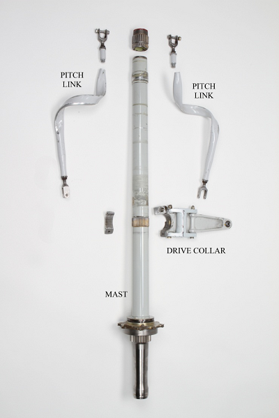
A freewheel assembly is installed on the engine accessory gearbox. The outer race of the freewheel assembly is splined directly to the power takeoff gear shaft. A sprag clutch transmits engine power to the inner shaft of the freewheel assembly. The forward end of the inner shaft drives the main-rotor transmission via a driveshaft that incorporates 2 flexible couplings to allow for transmission movement. The tail-rotor driveshaft is connected to the aft end of the freewheel assembly inner shaft as it exits the engine gearbox (Figure 1).

The freewheel assembly automatically engages to transmit engine power to the rotor drive train. When the engine is not producing power, the sprag clutch of the freewheel assembly provides an automatic disconnect from the engine and allows the rotation of the main rotor during autorotation to drive the transmission, tail-rotor and transmission mounted accessories.
Freewheel-assembly lubrication
The main-rotor transmission oil lubricates the freewheel assembly. The oil is filtered and passes through an oil cooler mounted on the transmission. Oil is then directed to the transmission's oil jets, pressure regulator and a reducer fitting (AN919-6D). The reducer serves as a port to direct oil via a flexible hose to a manifold mounted on the upper deck. The manifold houses a pressure transducer, pressure switch and a restrictor (P/N 206-040-254-001) that incorporates a 0.039- to 0.044-inch orifice. A flexible line delivers oil from the restrictor outlet to the aft end of the freewheel assembly. Oil flows forward to lubricate the bearings and clutch and drains into the freewheel-assembly housing before returning by gravity to the main-rotor transmission. The freewheel-assembly housing incorporates a magnetic chip plug. The restrictor must be inspected during a transmission serviceability check, which is required when metal particles are found on a main-rotor transmission chip plug. To prevent restrictor contamination caused by debris such as particles of cut o-rings from being discharged into the oil system during maintenance to the transmission and freewheel assembly, Bell Helicopter Technical Bulletin 206-79-31 had introduced a filter (P/N 50-075-1) that replaced the AN919-6D reducer. This technical bulletin was optional and had not been embodied.Footnote 2
Aircraft examination
Examination of the main- and tail-rotor drive train revealed that it had been affected by excessive torque. A main-rotor blade had struck the port side of the tail boom immediately forward of the horizontal stabilizer causing a small dent. The skid gear was inspected and there was no indication of spreading due to a hard landing. Damage to airframe components in the upper-deck area was consistent with excessive main-rotor-transmission movement.

Component testing and examination
Components removed for examination and testing included the engine, transmission and swashplate. The idler lever, drive link, collar set, pitch links, mast assembly, freewheel assembly and freewheel-assembly lubrication system were sent to the TSB Laboratory for examination. The magnetic chip plugs were removed from the main rotor transmission and freewheel assembly. The chip plugs were not contaminated. Inspection of the transmission revealed no defects. The clamp half of the collar set (P/N 206-011-005-109) that connects the swashplate idler lever and drive link to the mast had failed. The stud that secured the drive link to the swashplate outer ring was bent opposite to the direction of rotation. There were some impact marks on the horns of the inner-ring control plate. The pitch links were wrapped around the mast in a counter-clockwise direction as viewed from above. The pitch links had failed at the upper end at a point coincident with the end of the internal threads. (Photo 1) Score marks on the mast aligned with the fractured ends of the pitch links when the collective lever was fully raised. The main driveshaft (P/N 206-040-015-103) was examined visually and no defects were found.
Main-rotor transmission assembly
The transmission was installed on 15 February 2002 after having been overhauled. Since then, the transmission had accumulated approximately 1783 hours. The transmission underwent a 1500-hour inspection in 2010 during which the transmission oil-cooler inlet- and outlet-piping would have been disconnected. During the investigation, the interior of the transmission was inspected and no debris or corrosion was noted. Some metal particles were found in the lower-mast-bearing support area. The inlet fitting and the outlet pipe were removed from the oil cooler and there were indications that corrosion had occurred in these areas. The TSB Laboratory examined the corrosion products and the coating damage on an anodized aluminum union fitting (P/N AN815-10D) and the bottom end of the tube (P/N 206-040-192-001) that connects the oil cooler to the main rotor transmission. Metallurgical analysis showed that the aluminum- and magnesium based corrosion products detected in the restrictor debris originated from the union fitting and tube, respectively.
Mast assembly
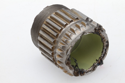
The mast (P/N 206-010-332-121) had failed below the main rotor attach splines (Photo 2). The splines exhibited signs of torsional yielding in that the lower splines were advanced in the direction of rotation approximately .040 inch in relation to the upper splines. The fracture surface of the lower portion of the mast was obliterated by rotation against the upper mast stub. The fracture surface of the upper mast portion was severely damaged by the lower mast spinning against it. Metal had been displaced and showed signs of local overheating (Photo 3). There were some fracture areas however that remained pristine. The mast diameter was measured at several places near the fracture and there were no indications that the mast was out of round, nor was any bending evident. Examination of the fracture surfaces of the upper mast stub revealed that the mast had failed in a ductile mode due to torsional stresses. The direction of fracture was consistent with the application of power from the engine. There were no signs of a pre-existing defect or progressive failure and material analysis results were consistent with specifications provided by the manufacturer.
Freewheel assembly examination
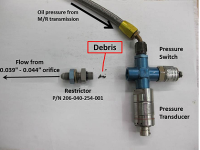
The freewheel assembly was installed on 16 March, 2004 with 100.2 hours of operation since having been overhauled. The clutch (P/N CL42250 1) was installed new when the freewheel assembly was overhauled. It had accumulated approximately 1162 hours since overhaul. The pressure and return lines that route oil to and from the freewheel assembly were examined. The outlet restrictor fitting (P/N 206-040-254-001) was removed from the manifold and was found to be blocked by debris (Photo 4). It could not be determined when the restrictor was last inspected. A review of the aircraft records did not reveal any instances of metal contamination of main rotor transmission chip plugs. The transmission oil lines had been flushed, but it could not be determined whether the restrictor was cleaned at that time.
The interior components of the freewheel unit were relatively dry and were coated with a residue of reddish-brown color and consistency ranging from oily to paste-like. A metallurgical analysis revealed that the residue was composed of oil and steel corrosion product (iron oxide or rust). Rust is a form of corrosion that results when the iron component of steel reacts with oxygen in the presence of water and creates an oxide that is red in color. Water can enter aircraft components by a variety of means including condensation, operation in rain and snow or during washing. It was evident that water had been present at some time however the source of the water could not be determined.
No wear particles were found. The sprag clutch raceway showed discoloration and multiple sprag engagement markings. The aft bearing showed signs of overheating and deterioration indicated by bluing and flat spots on the rollers. The outer diameter of the outer race showed circumferential rubbing marks consistent with rotation in its bore. The sprag clutch working surfaces showed some corrosion pitting as well as smearing consistent with heavy engagement. A representative sprag was selected for scanning electron microscope (SEM) examination. The working surface of the sprag showed surface deformation and smearing in the direction of engagement, consistent with clutch overload. Corrosion damage that predated the occurrence was also observed on the sprag surface. The driven side of the splines of the freewheel input shaft exhibited a non-uniform wear pattern that varied from forward to aft. Likewise, wear on the outboard bearing land was not uniform around the circumference.
Engine testing and examination
The engine with original fuel-control components was prepared for testing and was installed in a test cell. The engine and associated fuel-control components performed normally during all phases of the testing. To simulate a failed-freewheel-assembly engagement, the engine was accelerated from idle (63% N1 rpm) to full throttle with minimal load on the output shaft from the test cell dynamometer. In this condition an N1 rpm of 75% was sufficient to accelerate the N2 gear train until the governor held the N2 rpm steady at 104%.
TSB Laboratory examination results
Examination of the torque indicator revealed no useful information. Examination of the material blocking the outlet restrictor fitting (P/N 206-040-254-001) by SEM indicated that the material consisted mainly of corrosion products.
The following TSB Laboratory reports were completed:
- LP152/2011 Torque Indicator Examination
- LP153/2011 Examination of Helicopter Mast, Oil Cooler, Freewheel & Clutch Assemblies
Analysis
The crew responded decisively to an emergency at a critical stage of flight in close proximity to the ground, and performed a successful autorotation landing. Neither environmental nor operational factors contributed to the occurrence. The analysis will address technical aspects relating to the helicopter's drivetrain.
Bell TB 206-79-31 introduces a filter at the transmission oil outlet intended to prevent contamination of the restrictor. Although the filter was originally introduced to prevent particles of cut o-rings from contaminating the restrictor, it is likely that the filter would also be effective protection from other types of debris. This bulletin was optional and had not been incorporated, which increased the risk of contamination of the restrictor. The resulting reduction of oil flow may result in freewheel-assembly damage.
Since the installation of the freewheel assembly in March 2004, the aircraft had a relatively low annual utilization averaging approximately 145 hours per year interspersed with periods of inactivity. Chapter 10 of the Bell Standard Practices Manual provides procedures for aircraft preservation for storage and reactivation. However, there was no indication that these procedures were applied. The internal corrosion of the transmission oil cooler union, tube and freewheel assembly components predated the accident and indicates that water had been present in the transmission oil system. The transmission, oil cooler and piping had been installed in February 2002. Between then and March 2004, the aircraft flew approximately 722 hours so it is likely that the corrosion developed later. The investigation could not determine the source of the water contamination. It is likely that moisture was introduced into the transmission and freewheel oil system as condensation during periods of inactivity. The presence of moisture in the oil system would have led to corrosion in the freewheel assembly and transmission oil cooler fittings. This was indicated by the iron oxide paste that coated the internal components of the freewheel and pitting of the sprag surfaces, as well as the corrosion of the aluminum inlet union and magnesium outlet pipe attached to the transmission oil cooler. The pressure oil supply from the main rotor transmission to the freewheel assembly was reduced by a blockage at the restrictor (P/N 206-040-254-001) consisting of aluminum and magnesium corrosion products released from the transmission oil cooler union and pipe. The oil flow to the freewheel assembly was severely reduced. Operation without adequate lubrication resulted in damage and overheating of the already corroded internal components.
The freewheel assembly did not engage as the throttle was rolled on during a power recovery autorotation. As the helicopter was leveled with aft cyclic input, the rotor rpm began to decrease even though the engine began to spool up. The engine test runs indicated that an N1 rpm of 75% (12% above idle), was sufficient to accelerate an unloaded N2 gear train to approximately 104% N2 rpm. The rotor rpm decay indicates that the engine power was not being transmitted to the rotor system. When the sprag clutch suddenly engaged, the inertia built up in the N2 gear train was resisted by the mass of the decelerating main rotor resulting in the overstress failure of the mast. The acceleration of the lower portion of the mast instantly caused the pitch links to contact the swashplate drive link and break the collar set away from the mast. The swashplate outer ring was pulled around by the main rotor via the pitch links until the drive link rotated down and jammed against the inner (fixed) swashplate ring. The main rotor continued to decelerate and the pitch links wound around the spinning lower mast and pulled the main rotor blades to nearly 90° negative pitch before failing in tension. As the main rotor came to a stop it flapped to one side and a blade bumped into the tail boom. The metal particles found in the transmission lower mast bearing support area were generated by the lower mast abrading against the upper mast stub. The lower mast came to a stop when the crew shut down the engine.
Findings
Findings as to causes and contributing factors
- At some point, moisture had entered the transmission oil causing contamination and corrosion of the internal components of the freewheel assembly and oil system.
- Blockage of the restrictor fitting in the oil-supply line by corrosion products resulted in reduced oil flow.
- Operation of the freewheel assembly without adequate lubrication resulted in damage and overheating which impaired its proper functioning.
- When the damaged-freewheel assembly did not engage, engine power was not transmitted to the rotor drive train during an attempted power recovery autorotation.
- After touchdown, the freewheel engaged and the resultant torque spike severed the main rotor mast and caused torsional damage to the entire drive train.
Findings as to risk
- If optional Bell Helicopter Technical Bulletin 206-79-31 is not incorporated, there is a risk that the restrictor may become contaminated. The resulting reduction of oil flow may result in freewheel-assembly damage.
- If the procedures contained in Chapter 10 of the Bell Standard Practices Manual are not followed, there is a risk that corrosion may develop in aircraft components during periods of inactivity.
This report concludes the Transportation Safety Board's investigation into this occurrence. Consequently, the Board authorized the release of this report on . It was released on .