
Air transportation safety investigation A14Q0068
Uncontained turbine rotor failure
Bombardier Inc.
BD-500-1A10 (C Series CS100), C-FBCS
Montréal International (Mirabel) Airport, Quebec
The Transportation Safety Board of Canada (TSB) investigated this occurrence for the purpose of advancing transportation safety. It is not the function of the Board to assign fault or determine civil or criminal liability. This report is not created for use in the context of legal, disciplinary or other proceedings. See Ownership and use of content.
-
Table of contents
Summary
On 29 May 2014, a Bombardier C series CS100, registration C-FBCS, serial number 50001, with 2 pilots and 4 test engineers on board was conducting engine ground runs at the Montréal International (Mirabel) Airport, Quebec. During the test, at 1837 Eastern Daylight Time, the left engine (Pratt & Whitney Canada model PW1524G) experienced a sudden power loss caused by an uncontained turbine rotor failure. After having been advised of smoke and fire from the engine, the crew immediately secured the engine and declared an emergency. All personnel on board evacuated the aircraft. Bombardier ground personnel successfully extinguished the fire. There were no injuries, but the engine and aircraft sustained substantial damage.
1.0 Factual information
1.1 History of the flight
On the day of the occurrence (29 May 2014), Bombardier and Pratt & Whitney planned to conduct engine ground runs on a Bombardier CS100 aircraft, referred to as Flight Test Vehicle 1 (FTV1, registration C-FBCS, serial number 50001), in 2 distinct phases. The first phase was to run the right engine at various predetermined power settings in order for Pratt & Whitney Footnote 1 engineering personnel to gather cabin air samples. This sampling was part of an ongoing effort to isolate the cause of an oil smell in the cabin and cockpit that was first noticed in early November 2013.
The second phase was to run the left engine, also at various predetermined power settings, in order to leak-check an oil pump assembly that had been replaced the previous evening as part of an effort to troubleshoot an oil consumption issue. This second phase was to be conducted in 2 parts. The first part of the engine ground run would be carried out with the thrust reverser doors open, then the engine would be shut down and the thrust reverser doors would be closed and secured. The engine would then be restarted for the second part of the engine ground run.
The plan called for 2 Bombardier test pilots Footnote 2 to be at the aircraft's controls in the cockpit, while 2 test engineers (one from Bombardier, the other from Pratt & Whitney) carried out monitoring duties in the cabin. Two additional Pratt & Whitney engineers, also in the cabin, would conduct air sampling. Once an agreement had been reached on the test plan, the crew proceeded to the aircraft at 1400. Footnote 3
The aircraft was parked on Road 408 Footnote 4 at the Montréal International (Mirabel) Airport (CYMX), Quebec. An enclosed trailer that Bombardier uses to support engine ground runs was parked nearby. It contained various pieces of support and servicing equipment and tools, including wheeled fire extinguishers. There were 2 Bombardier aircraft maintenance engineers on standby in a nearby van, and 2 avionics technicians on the left side of the aircraft, near the nose wheel, one of whom communicated with the cockpit crew through the aircraft's built-in intercom system. Two additional aircraft maintenance engineers and a Pratt & Whitney engineer also stood on the left side of the aircraft, forward of the wing tip.
The flight crew and accompanying engineers boarded the aircraft using wheeled access stairs at the left front door. The flight crew then briefed the cabin occupants on the customary safety and emergency procedures and features of the aircraft.
After the flight crew completed their pre-run checklists, the right engine was started at 1514. The required tests and air sampling were carried out uneventfully and were completed at around 1700. The right engine was kept idling as a replacement Bombardier flight test engineer boarded the aircraft at 1718 to relieve the one on board, whose work shift had ended, and the passenger door was closed.
At 1723:56, dry motoring Footnote 5 of the left engine was carried out for 1 minute and 38 seconds, and the engine was then left to spool down. For the next 11 minutes and 51 seconds, maintenance ground technicians ascertained whether there was any leakage from the replaced oil pump assembly on the left engine. No leak was found.
At 1738:20, the left engine was started and kept idling for 7 minutes and 53 seconds before being shut down. While keeping the right engine at idle, the ground crew again checked for oil leaks and closed the thrust reverser doors on the left engine. No leak was found.
At 1807:40, the left engine was restarted for an idle run of 6 minutes and 1 second. At 1814:27, the power level of the left engine was increased to 60% N1, Footnote 6 according to the test plan, and kept at that setting for 15 minutes and 8 seconds. At 1831:15, the left engine power level N1 was increased to 74%, where it stabilized at 1832:02. After the left engine had been running at that power setting for 5 minutes and 45 seconds, an explosion occurred in the left engine, which immediately began to spool down.
At 1837:52, upon seeing the explosion, 2 Bombardier ground crew exited the van parked nearby and ran toward the trailer parked on the right and aft of the aircraft, which contained the wheeled fire extinguishers. In the meantime, the ground crew technician advised the flight crew, through the intercom, that there had been an explosion.
The cockpit crew received no fire warning indication but did receive ENG VIBRATION, L ENG FIRE DET FAIL, and FIRE SYSTEM FAULT warnings on the screen of the engine indication and crew alerting system (EICAS). Once informed by the ground crew that there was fire on top of the left wing, the pilot-in–command (PIC) secured the left engine and shut down the right engine but did not discharge any fire bottles. The PIC ordered the co-pilot to arm the evacuation slides and to call for firefighting coverage, then used the intercom system to order the other occupants to evacuate through the right front door. The co-pilot called the airport's radio frequency to request aircraft rescue and firefighting (ARFF) assistance. He also ordered to “leave everything” and repeated this order, as some occupants were initially carrying personal equipment to the front right door.
At 1838:25, the PIC requested confirmation from the ground crew that there was a fire and was again informed that there was fire and smoke over the left wing.
At 1838:58, the right front door's emergency evacuation slide was armed, and the door was immediately opened. Once the slide was deployed, all of the aircraft's occupants immediately began to evacuate. The PIC switched off the electric power in the aircraft and subsequently evacuated the aircraft last.
At 1840:15, the first fire extinguisher (containing carbon dioxide) was discharged on the burning engine by Bombardier personnel. The second fire extinguisher (containing dry chemical) was also discharged and extinguished the fire. ARFF personnel arrived on scene at 1842:20. At 1845:17, ARFF vehicles dispensed the first spray of fire suppressant foam and water on the engine and wing. At 1851, ARFF personnel officially declared the fire extinguished. At 2041, the aircraft was towed back to the Bombardier hangar and quarantined for the investigation.
1.2 Injuries to persons
No injuries were reported.
1.3 Damage to the aircraft
Initial inspection revealed that the left engine sustained an uncontained failure in the low-pressure turbine's first stage area and that debris from the engine caused substantial damage to the airframe as well as lighter damage to various specific areas, including
- wing's lower surfaces
- wing-to-fuselage fairing panels
- wing leading edge slats
- flap fairings
- landing gear door panels and actuating mechanisms
- landing gear strut and braces
- fuel inerting equipment.
For more detailed information, see section 1.12, Wreckage and impact information.
1.4 Other damage
Not applicable.
1.5 Personnel information
The cockpit crew consisted of qualified Bombardier Flight Test Centre engineering test pilots who were authorized to conduct engine ground runs in accordance with Bombardier Flight Test Standards and Procedures. Footnote 7 There was no indication that crew fatigue was a contributing factor in this occurence.
1.6 Aircraft information
1.6.1 General
Bombardier announced the development of the C Series aircraft in July 2004 (Figure 1) In November 2007, Bombardier announced that the Pratt & Whitney Canada PW1500G geared turbofan engine would power these aircraft. Two variants of the C Series aircraft are offered: the 108–125 passenger CS100 and the 130–160 passenger CS300.

Basic information for the occurrence aircraft is summarized in the following table.
| Manufacturer | Bombardier Inc. |
|---|---|
| Model | BD-500-1A10 |
| Serial number | 50001 |
| Registration marks | C-FBCS |
| Certificate of registration issue date | 06 May 2013 |
| Flight permit issue date | 29 August 2013 |
| First flight | 16 September 2013 |
| Total airframe flight hours * | 177.3 |
| Total airframe cycles * | 71 |
* Accumulated at the time of the occurrence
The C Series contains approximately 70% advanced materials: approximately 46% composite materials (carbon-fibre–reinforced polymer), mainly in its wings, empennage, and engine nacelles, and approximately 24% aluminum-lithium, mainly in its fuselage (Figure 2).

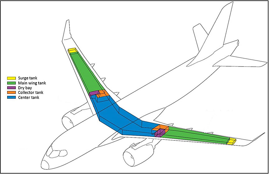
1.6.2 Wings
The centre wing box and the outer wings are made of box spar construction and house the fuel tanks (Figure 3). The left and right main wing fuel tanks are located outboard of the engine pylons. The left and right dry bays and collector tanks are located just inboard of the engine pylons. The centre tank occupies the remaining middle portion of the wing. The wings are made primarily of carbon-fibre–reinforced polymer and comprise the wing skins, stringers, spars, and spar caps, as well as the wing ribs, which are made of aluminum.
1.6.3 Fuel tank inerting system
Fuel tank inerting systems (FTIS) are integrated into new aircraft designs as a means to comply with current aircraft design standards. Footnote 8 An FTIS reduces the chance of the fuel tanks igniting as a result of an in-tank ignition source. It floods the fuel tank ullage Footnote 9 space with an inert gas stream, which reduces oxygen concentration to 12% or less, thus inhibiting combustion.
The FTIS uses bleed air from the engine or auxiliary power unit (APU) and outputs nitrogen-enriched air (NEA). This non-flammable mixture is then routed to the fuel tanks, filling the ullage space with NEA. Major system components are housed in the wing-to-fuselage fairings, with the necessary control components located in the mid-fuselage avionics bay. Distribution pipes route the NEA to the fuel tanks.
At the time of the occurrence, there were 23 475 pounds of fuel on board. The centre fuel tank contained 12 200 pounds of fuel, representing 47.6% of its capacity.
The main piece of debris that entered the centre fuel tank penetrated the tank just outboard of the fuel level (Figure 4), traversed the ullage space, and burst through the top skin of the wing, where it became stuck. The absence of any large-scale traces of fire demonstrates that the FTIS functioned as designed during this occurrence.

1.6.4 Cabin configuration
The aircraft involved in the occurrence was the first prototype of the C Series aircraft and was designed as a flight test vehicle. As a consequence, it did not feature all of the cabin amenities normally found on in-service airliners. Instead, it was fitted with flight engineer work stations and with solid and liquid ballast systems used to manage the aircraft's centre of gravity in flight. The cabin door configuration is illustrated in Figure 5.

The forward and aft passenger and service doors were all fitted with functional inflatable evacuation slides. The overwing emergency doors, although fully operable, were not fitted with slides. At the time of the occurrence, only the slide for the aft left-hand door was armed to automatically deploy upon the door's opening. When the decision to evacuate was made, the crew armed the slide at the forward right-hand door (1R, Figure 5), and all occupants evacuated the aircraft through this door. There was no written procedure governing the arming configuration of evacuation slides during engine ground runs.
1.6.5 Engine fire detection and extinguishing systems
The engine fire detection system alerts the crew to a fire condition in the engines. For each engine, the engine fire detectors are arranged in a dual-loop configuration designated as loop A and loop B, each connected to its respective control unit channel. One element is mounted on the pylon, and 2 elements are mounted on each core cowl (Figure 6).

The crew is alerted to an engine fire by the illumination of the L or R ENG FIRE push button. A FIRE light on the engine start panel provides a cue to shut down the affected engine. Additionally, there is a message on the crew alerting system (CAS) and an audio warning.
The engine fire extinguishing system provides the fire extinguishing capabilities for the left and the right engines. The system has 2 fire extinguisher bottles mounted on the aft spar, just forward of the main landing gear bay. Each extinguisher has 2 discharge heads and can be selected for discharge into either engine.
Check tees direct the extinguishing agent into the engines, and discharge nozzles direct it to the fire zones in the engines. The fire extinguishers are discharged using the appropriate engine FIRE push button annunciator (PBA) and bottle (BTL) PBAs located on the ENGINE and APU FIRE panel. Pressing the FIRE PBA shuts down the engine, isolates the engine from the airframe systems, and arms the fire extinguishers for discharge. When the BTL PBA is pressed, the corresponding bottle discharges into the engine.
During the occurrence, the engine fire detector loops were severed by rotor disk debris, and there was no fire warning in the cockpit. However, the EICAS generated several warnings as the engine spooled down, one of which was an L ENG FIRE DET FAIL indication on the cockpit EICAS screen. When this type of indication appears, the procedure calls for monitoring the engine instruments.
Following the occurrence, it was determined that the fire extinguishing system had not been compromised by the uncontained rotor failure and could have been activated to suppress the fire.
1.6.6 Engine nacelles
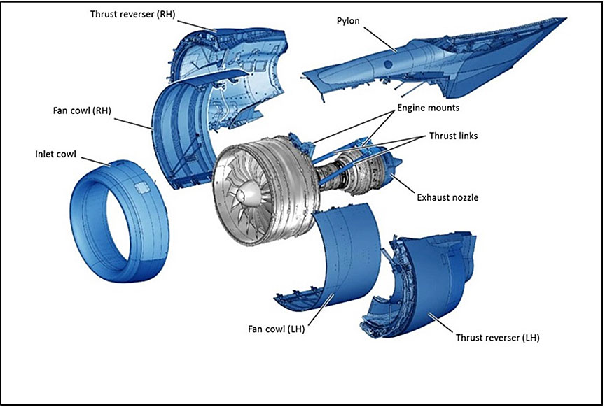
The engine nacelles are built mainly from composite materials. The inlet cowls, exhaust nozzles, and exhaust centrebodies are mounted directly to the engines, whereas the fan cowls and thrust reversers are mounted to the engine pylon assemblies.
The thrust reversers comprise an inner fixed structure, which covers the engine core, and a mobile outer section—the translating sleeve—which moves aft as thrust reverser command is applied (Figure 7).
1.6.7 Engines
The occurrence engine differed from the final type-certified version in many respects, mainly involving monitoring instrumentation hardware and software. However, the components that were involved in the occurrence were essentially the same as those in the final type-certified version. This report will refer to the engine as a PW1524G, unless reference is made specifically to the occurrence engine, in which case it will be referred to as an XPW1524G.
The PW1524G is a twin-spool, axial-flow, ultra-high–bypass ratio geared turbofan engine that includes core-mounted angle and main gearboxes (Figure 8). It is part of the PW1000G family of geared turbofan engines that were first run in 2008; the family comprises variants ranging from 15 000 pounds (66.75 kilonewtons [kN]) to 33 000 pounds (146.85 kN) of static thrust. The PW1524G variant, specifically developed for the C Series aircraft, delivers 24 400 pounds (108.5 kN) of thrust.

Testing of the PW1524G began in October 2010, and the engine received type-certification by Transport Canada (TC) on 20 February 2013 (type certificate number E-38). At the time of the occurrence, there were only a few engines of the PW1500G family manufactured; all were used in the C Series aircraft development program. The C Series aircraft had not yet been type-certified.
The PW1500G family of engines features modular construction (Figure 9). The engine's rotating assemblies are interrelated as follows:
- The 3-stage low-pressure compressor is connected by a central axial shaft at its back end to the front end of a 3-stage low-pressure turbine (LPT) and is referred to as N1 for instrumentation purposes.
- The front end of the low-pressure compressor is connected to the fan drive gear system, which is in turn connected to the fan rotor.
- The 8-stage high-pressure compressor is connected to the front end of the 2-stage high-pressure turbine (HPT) by a surrounding axial shaft at its back end and is referred to as N2 for instrumentation purposes.

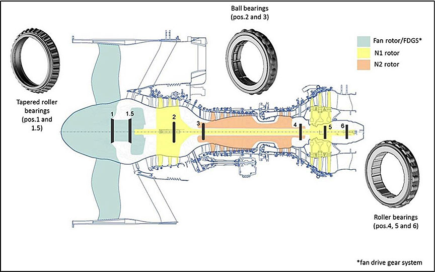
1.6.7.1 Engine main bearings
The rotating assemblies of the PW1524G engine are supported by bearings. The weight of the parts is transmitted through tapered–roller, ball, or roller-type bearings. Bearing types and locations are shown in Figure 10.
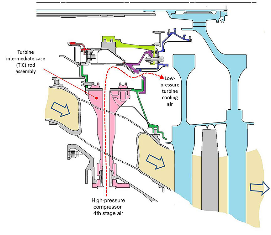
1.6.7.2 Turbine intermediate case
The turbine intermediate case (TIC) consists of outer and inner case assemblies joined by 14 shrouds. As the hot gas exits the HPT, it flows between these shrouds on its way to the LPT (Photo 1).

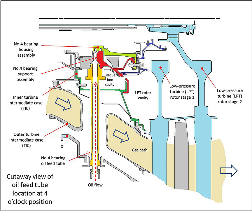
TIC rod assemblies reside at the centre of 7 of the shrouds and mechanically link the inner and outer TIC cases; each of these TIC rod assemblies provides a flow path, down its hollow centre, for LPT cooling air coming from the fourth stage of the high-pressure compressor into the torque box. The torque box is the chamber formed by the inner case assembly and the bearing support assembly, where the air from the TIC rods collects and flows out the cooling holes of the No. 4 bearing support assembly into the LPT rotor cavity (Figure 11).
The 4 remaining shrouds house service tubes for the No. 4 bearing, namely, the oil feed tube (Figure 12), the oil scavenge tube, the oil scupper tube, and the buffer tube.
1.6.8 Engine failure sequence
The engine teardown allowed investigators to determine what led to the uncontained failure of the aircraft's left engine.
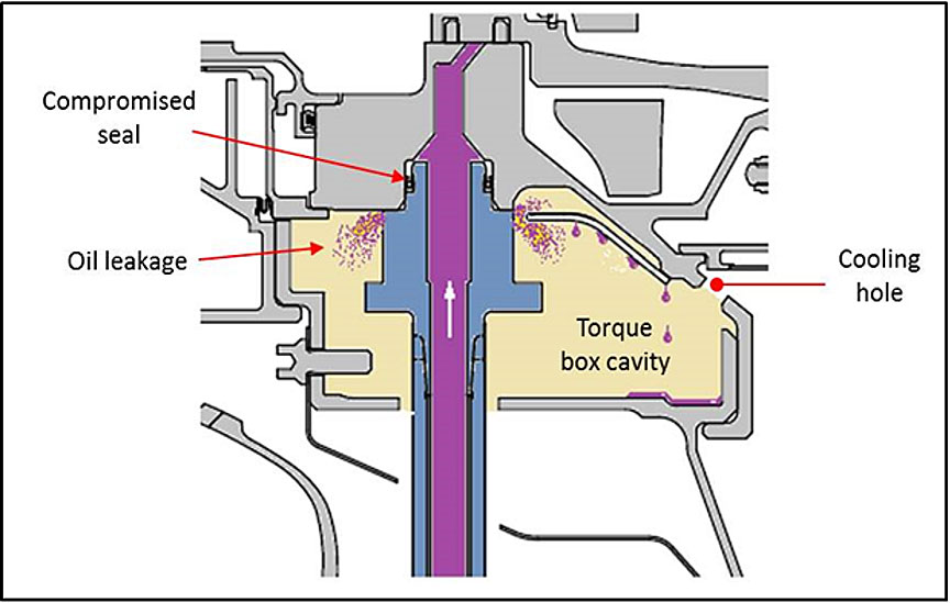
While running at 74% N1, oil under pressure began leaking into the torque box cavity from the mating surface between the flange of the oil feed tube for the No. 4 bearing and the TIC assembly. From that point, the leaked oil merged with the cooling airflow. The cooling air and the leaked oil transited through the torque box, through the nearby cooling holes, and into the rotor cavity (Figure 13).
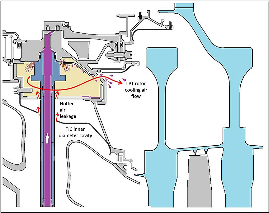
The oil feed tube for the No. 4 bearing runs upward from the outer case of the engine (at approximately the 4 o'clock position viewed looking forward), through a hole in the TIC inner case assembly, on its way to the bearing support assembly, which sits at the core of the engine. The diameter of the hole is slightly larger than the diameter of the oil feed tube. The resulting circumferential gap allows a certain amount of air flow between the TIC inner diameter (ID) cavity and the torque box cavity. As a result, TIC ID air, which is hot owing to its proximity to the gas path, enters the torque box (Figure 14).
The temperature of the air in the torque box cavity was below the auto-ignition point of the leaked oil during the 15 minute and 8 second stint at 60% N1. As the engine reached 74% N1, the cooling air temperature in the torque box rose, as it was expected and designed to do, as a result of being exposed to the hotter flow of the gas path as it made its way down and around the TIC rods (Figure 14). When the temperature in the torque box surpassed the auto-ignition point of the leaked oil, the leaked oil ignited in the torque box. The resulting fire, which was fed in a continuous manner, flowed out into the rotor cavity, following the cooling airflow out the nearest cooling holes, located in the bearing support assembly. The fire then impinged upon the front face of the rotor disk, overheating the web of the disk until centrifugal force led to failure from tensile overload (Figure 15).

1.6.9 Maintenance records
Bombardier maintains complete maintenance records for the airframe, whereas Pratt & Whitney maintains complete maintenance records for the engines. Also, because of the experimental and developmental nature of the program, extensive telemetry data and video footage are generated for each engine ground run and test flight. A review of the records revealed that all pertinent maintenance actions were recorded and on file.
1.6.10 Procedures development
In the context of new aircraft development, the engine manufacturer generally oversees the issuance and revisions of engine-related procedures and instructions. The PW1500G installation and operating manual (IOM), which is applicable to the PW1524G model, establishes the engine operating procedures and limits that must be adhered to at all times. The content of this document may be supplemented by Restriction and/or Special Instructions (RSI).
1.6.10.1 Restriction and/or Special Instructions approval
Pratt & Whitney is responsible for generating the powerplant RSIs requested by Bombardier and related to Pratt & Whitney's systems and hardware. It is also Pratt & Whitney's responsibility to define the limitations and inspections on its system components. Most limitations and inspections are ultimately found in documents such as Bombardier's Preliminary Operating Procedures Manual or Flight Test Vehicle Maintenance Manual. However, if these limitations and inspections are short-term and not expected to be a requirement for in-service operations, they are covered by RSIs, which are better suited for shorter-term action and are easier to update and track. Although the engine RSIs are issued by Bombardier and bear Bombardier logos, the initial RSI and subsequent changes are developed, reviewed, and approved both by Bombardier and by Pratt & Whitney, with concurrence by Pratt & Whitney Canada's type certificate representative when required, before submission to Bombardier for its approval.
1.6.10.2 Initial cooldown procedure
The Pratt & Whitney PW1500G IOM stipulates the proper procedure to use when shutting down the engine. The initial version of the manual, dated 08 January 2013, stated that the engine should be operated below (approximately) 70% N2 for a minimum of 10 minutes before shutdown. According to the IOM, this was to ensure proper cooling in order to minimize the potential for oil coking Footnote 10 in the main engine bearing compartments and to mitigate a bowed rotor start condition. Footnote 11 This requirement was retained in the various successive amendments of the manual up until the occurrence.
1.6.10.3 Revised cooldown procedure
At Bombardier's request, Pratt & Whitney released RSI No. C-500-001-71-0011 Footnote 12 on 08 July 2013, providing Bombardier with the following alternatives to the 10-minute cooling period specified in the IOM:
- Operate engine between minimum and flight idle power for 5 minutes, provided airflow through the engine inlet is 5 knots or higher until restart or EGT [exhaust gas temperature] reaches 90degC, whichever comes first.
- If cooling airflow cannot be guaranteed, carry out either of the following prior to shutdown:
- Cool down at flight idle power for 10 minutes.
- Cool down between minimum and flight idle power for 15 minutes.
- If the engine must be shutdown prior to 5 minutes at minimum idle, or none of the procedures in 1) or 2) could be followed, carry out the following:
- If subsequent restart is possible, restart the engine within 20 minutes and carry out Cool Down procedure 2.a or 2.b before shutting down again if required — for continued engine operation, stabilize at min idle for 5 minutes before unrestricted operation.
- If restart is not possible but cranking is possible, crank the engine within 20 minutes for a duration of 90 seconds and repeat every 20 minutes until EGT is stabilized below 90degC or a total of 5 cranks are completed. EGT stabilization check is to be done after N2=0 for at least 5 minutes.
- If neither crank or restart is possible within 20 minutes, do not start the engine for the subsequent 8 hours or until indicated EGT in the cockpit is stabilized below 90degC.
Following the release of RSI No. F-500-001-71-0011, there were 4 documented instances in which the occurrence engine was shut down under the provision of Section 3.c. of the RSI.
| Date | Deviation from the required 5-minute below 75% N2 (cooldown) period before shutdown |
|---|---|
| 09 September 2013 | 4-minute cooldown before shutdown |
| 16 September 2013 | 10-second accelerate/decelerate stint to 78% N2 at 2 minutes before shutdown |
| 16 January 2014 | 3-minute cooldown before shutdown |
| 17 March 2014 | 4.5-minute cooldown before shutdown |
In April 2014, after consultation between Pratt & Whitney and Bombardier, Pratt & Whitney issued and Bombardier approved, Revision A (rev.A) to RSI No. F-500-001-71-0011.
Revision A was similar to the original RSI, but it removed the 5-knot airflow requirement, thereby allowing a 5-minute cooldown period in all circumstances.
After RSI No. F-500-001-71-0011 rev. A was issued, there were 2 instances in which the occurrence engine was shut down under provision 2.c. of this RSI (previously 3.c. in original version of the RSI).
Another hot shutdown occurred on 26 May 2014, when the engine was operated at 78% N2 for 118 seconds, followed by an approximately 19-second cooldown before shutdown. The engine was restarted approximately 50 minutes later. The exhaust gas temperature (EGT) indicated in the cockpit was 99 °C when the engine was restarted.
| Date | Deviation from the required 5-minute below 75% N2 (cooldown) period before shutdown |
|---|---|
| 11 May 2014 | 4-minute cooldown before shutdown |
| 21 May 2014 | 2-minute dwell at 95%N2, then idle cooldown for 45 seconds before shutdown |
| Date | Deviation from the required 5-minute below 75% N2 (cooldown) period before shutdown |
|---|---|
| 26 May 2014 | 118 seconds at 78% N2, 19-second cooldown and restart 50 minutes later at EGT = 99 °C |
In a memo to Bombardier dated March 2014, Pratt & Whitney explained that, during development, Pratt & Whitney had conducted bowed rotor start testing on a test engine to evaluate minimum idle cooldown times for engines in service and that test results showed that a 5-minute idle cooldown was optimum. This requirement was slated to be specified in a future revision to the IOM. Both versions of the RSI cited on their header page:
The engine cool down procedure included in the referenced Installation and Operating Manual (IOM) specifies cool down at flight idle in order to mitigate bowed rotor start conditions and minimize the potential for oil coking in the main engine bearing compartments.
Aside from the references to bowed rotor and oil coking, there was no mention of other potential detrimental effects on the engine that could result from the use of the procedure contained in the RSI, namely, sections 3.c. (of the original RSI) and 2.c. (of rev.A), and no express requirement in the RSI for Bombardier to notify Pratt & Whitney of the occurrence of a hot shutdown.
1.6.11 Occurrence engine maintenance history
It is important to note that, in the context of the development of new aircraft such as the C Series, many parts and/or components are replaced with new, modified, or updated versions as the development evolves. These replacements are concurrent with regular maintenance actions. Therefore, the maintenance records typically contain a mix of development-related work and actual maintenance. This maintenance information was documented in the engine records maintained by Pratt & Whitney, and airframe work was recorded in Bombardier's records system.
A review of the occurrence engine records revealed the following activities:
- On 13 December 2012, the occurrence engine (serial number P735901) was stated as having been built and released as an XPW1524G, with a restriction that it was not to be used on a certified aircraft. Records also stated that Pratt & Whitney tested the engine in conformity with its build specification and deemed it safe and satisfactory for installation within the limitations specified in its logbook.
- The engine was installed on the left wing of FTV1 on 31 January 2013.
- The engine underwent several planned parts replacement and inspections between its installation on the wing and the occurrence.
- Regular maintenance was carried out; this included fuel filter replacements and fan blade root inspections.
- Several borescope inspections were carried out as part of the effort to troubleshoot the oil smell.
- The main engine oil pump assembly was replaced the evening before the occurrence in an effort to isolate the cause of the excessive engine oil consumption.
- In the days preceding the engine incident, Bombardier and Pratt & Whitney were jointly troubleshooting an issue of increasing oil consumption on the occurrence engine.
1.6.12 Aeronautical product certification
The certification of any aeronautical product, such as an aircraft or aircraft engine, indicates that it complies with a recognized set of standards. For Canadian-developed aeronautical products, such as the Bombardier C Series aircraft and the Pratt & Whitney Canada model PW1524G engine, the recognized standard is a design standard prescribed by TC.
TC's Standards Branch establishes and regulates standards for aeronautical products designed and operated in Canada. TC's National Aircraft Certification Branch provides the industry with guidance on aeronautical products certification and issues design approvals. The process for approval of an aeronautical product in Canada is governed by Part V, Subpart 21 of the Canadian Aviation Regulations (CARs). Footnote 13 When a design organization wishes to obtain design approval for a new aeronautical product, it submits an application to TC for a type certificate, a document issued by the Minister of Transport that certifies that the type design of an aeronautical product meets the applicable standards. There are basically 4 phases to the type certification process for an aeronautical product:
- The certification basis that the aeronautical product must meet is established. That certification basis consists of the applicable airworthiness requirements and emission standards of the Airworthiness Manual, Footnote 14 any special conditions, any equivalent safety findings, any exemptions, and election to comply with later standards. This certification basis will not change for that aeronautical product, even if the design standard changes after the certification basis has been agreed upon.
- TC and the applicant agree on the certification plan. The application is generally limited to a specific period, during which the design organization must establish that the proposed aviation product complies with the agreed certification basis. If the application process exceeds that time limit, the period can be extended; however, the certification basis may be revised to encompass later standards.
- Compliance with the standard is demonstrated through the completion of the general compliance plan, which comprises numerous tests and analyses.
- Upon successful completion of the certification program, a number of documents related to the results of the certification program, as well as continued airworthiness, are developed and submitted. Finally, TC issues a type certificate. The type design is described by the type certificate data sheet (TCDS) and its associated reference documents, including approved manuals and any limitations associated with its operation or maintenance.
1.6.13 Aircraft certification
1.6.13.1 Airframe certification standard
The Bombardier C Series CS100 (model BD500-1A10) is designed to meet the applicable requirements set out by TC in Airworthiness Manual Chapter 525 (AWM 525), Footnote 15 which details the airworthiness requirements for transport category aeroplanes, contained in the certification basis. The requirements of AWM 525 are primarily based on and derived from those of Part 25 of the United States Federal Aviation Administration's (FAA) Title 14 of the Code of Federal Regulations (commonly known as FAR 25) Footnote 16 in addition to technical conditions unique to Canada.
The airframe certification standard addressing the effects to the aircraft of uncontained engine rotor failures is AWM 525.903(d)(1), which states, in the case of turbine engine installations, “Design precautions must be taken to minimize the hazards to the aeroplane in the event of an engine rotor failure or of a fire originating within the engine which burns through the engine case.”
These requirements are further defined in FAA Advisory Circular (AC) 20-128A. Footnote 17 This advisory material evolved from the lessons learned from the investigation of a number of uncontained engine rotor failure accidents in which the resulting damage was analyzed by the relevant airworthiness authorities.
At the time of the occurrence, the Bombardier C Series aircraft model was still in the certification process and had not yet received its type certificate from TC. Footnote 18
1.6.14 Engine certification
Pratt & Whitney Canada applied for type certification of the PW1500G engine family in September 2009. After demonstrating compliance with the requirements contained in AWM Chapter 533 (at revision 533-12), Footnote 19 which defines airworthiness requirements for aircraft engines, TC issued the type certificate (No. E-38) on 20 February 2013.
1.7 Meteorological information
No significant weather was observed at CYMX at the time of the occurrence, and ground crews reported weather conditions consistent with the recorded data (Table 5). Weather conditions are not considered a factor in this occurrence.
| Temperature | Dew point | Humidity | Pressure | Visibility | Wind direction | Wind speed | Precipitation | Conditions |
|---|---|---|---|---|---|---|---|---|
| 18.0°C | 8.0°C | 52% | 1019.4 hPa | 72.4 km | 250 | Calm | None | Cloudy |
1.8 Aids to navigation
Not applicable.
1.9 Communications
FTV1 was fitted with an intercom system consisting of 2 flight crew audio panels: 1 service interphone panel for communicating with a technician standing outside the aircraft and 4 flight test engineer audio control panels located in the cabin. The system was designed to ensure continuous availability in normal and emergency conditions. The investigation concluded that there were no communications issues related to this occurrence.
1.10 Aerodrome information
CYMX is located 39 km northwest of Montréal, Quebec. It features 2 runways 12 000 feet long and a tower providing airport advisory services. It is also the site of major manufacturing facilities, 2 of which are operated by Bombardier and Pratt & Whitney Canada, which carry out the final assembly of the C Series aircraft and the PW1500G family of engines, respectively. The airport has a fully staffed and equipped ARFF service. The ARFF station is located approximately 2400 metres from the occurrence site.
1.11 Flight recorders
Both the flight data recorder (FDR) and the cockpit voice recorder (CVR) from the occurrence aircraft were delivered to the TSB Laboratory on 03 June 2014 for data retrieval.
1.11.1 Flight data recorder
The FDR was a model FA5000 solid-state recorder manufactured by L3 Communications and was received in an undamaged condition. Since the occurrence aircraft was a pre-production aircraft, the recorded data on the FDR were neither complete nor reliable.
1.11.2 Cockpit voice recorder
The CVR was also a solid-state L3 Communications model FA5000. Affixed to the CVR was a recorder independent power supply, which provides an additional 10 minutes of recording when power to the CVR is removed. Four audio tracks, including the PIC's and first officer's channels, the cockpit area microphone channel, and an extra channel were recovered in waveform audio file (.wav) format. All recordings were exactly 2 hours long.
The aircraft beacon light was not selected on for the engine test run. This is one of the parameters required by the recording logic of the CVR; as a result, the occurrence was not captured on the recovered audio files.
1.11.3 Other recorders
The occurrence aircraft was equipped with several on-board cameras recording cockpit instrument data as well as several outside view angles. All of the camera views were time-stamped and synchronized. The aircraft also broadcast extensive live data to a telemetry room located in a nearby building, where the data were recorded and monitored in real time by engineering personnel. The resulting video recordings and telemetry-recorded data were instrumental in the conduct of this investigation.
1.12 Wreckage and impact information
1.12.1 Left-engine nacelle damage
There was substantial damage to the left-engine outboard thrust reverser cowl as debris penetrated the carbon-fibre–composite core fairing section and the aft edge of the translating sleeve at approximately the 10 o'clock position (fuselage station [FS] Footnote 20 770). Some soot was also evident around the damaged area.
The inboard thrust reverser cowl also sustained damage, as debris exited outward in an arc between the 1 and 5 o'clock positions (at FS 770), breaking away most of the aft end of the core fairing and translating sleeve (Photo 2).

1.12.2 Left-engine support structure damage
The weldment assembly on the outboard side of the engine pylon sustained penetration damage measuring 4 × 2 inches, along with secondary debris impact damage in the immediate vicinity.
1.12.3 Left-wing structure damage
The left-wing structure sustained major debris impact damage when a segment of the first-stage LPT rotor disk 28 inches long penetrated the wing's centre fuel tank (Photo 3).

The impact created a span-wise gash 33 inches long and 3 inches wide in the carbon composite lower skin plank, inboard of the engine at wing rib No. 6 and extending to rib No. 5, just aft of the forward wing spar, with a total delamination area of 16 × 37 inches. The lower wing stringer (No. 10), ribs Nos. 5 and 6, the lower spar cap, a fuel vent system line, and a float valve were severed by debris impact.
The turbine disk segment then partially exited through the upper wing plank, where it remained stuck, creating a hole approximately 13 × 7 inches, with a total delamination area of 21 × 10 inches. Signs of burning were found around the hole, although the fuel contained in the tank did not ignite (Photo 4).

1.12.4 Right-engine nacelle damage
A piece of debris punctured through the right engine inboard thrust reverser cowl translating sleeve, resulting in a hole 13.2 × 10 inches at the 2 o'clock position. A blocker door strut at this location was broken off and missing, and a piece of debris punctured through the inner cowl fairing, although the underlying engine core was not damaged (Photo 5).

1.12.5 Left engine damage
The main damage was found in the area of the first stage of the LPT. The initial visual examination of the engine while still on-wing revealed that the LPT case was breached around 95% of its circumference (Photo 6). The sole unbreached area was located at approximately the 8 o'clock position.

The first stage disk of the LPT was missing, except for an ovalized, donut-shaped remnant of the bore resting on the centre shaft. There were significant signs of fire on the inboard core cowl, characterized by soot, deformation, and melted composite materials from the cowl.
The left side thrust link was severed in line with the LPT plane; some engine-air and -oil lines, as well as some electrical wires and fire detection loops, were damaged or severed in the vicinity of the LPT case breach (Photo 7).

The engine was removed from the wing the day after the occurrence and was transferred to Pratt & Whitney's Middletown, Connecticut, United States, facility for teardown under TSB supervision.
Step-by-step disassembly revealed further damage. Initial removal of the LPT from the TIC, which houses the No. 4 bearing compartment, revealed severe heat distress on the TIC's aft face, concentrated at the 4 o'clock position. Figure 16 illustrates the location of the following damage observed:
- breach in the TIC wall (Figure 16, A)
- heat damage to No. 4 bearing housing flange (B)
- bolt missing at the No. 4 bearing compartment housing flange (nut plate with bolt stem found in TIC) and some heat-damaged bolt heads nearby (C)
- heat damage to outer diameter of No. 4 bearing compartment buffer cavity (D)
- damaged inner or missing outer brush seals around main shaft (E)
- missing outer brush seal housing and shaft land (F).

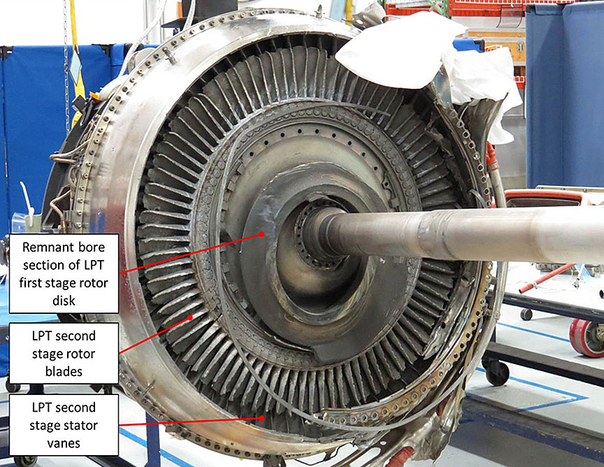
The bore section was the only remnant of the LPT first stage rotor found within the engine, hanging loosely on the LPT shaft. The first stage vanes, which are integral to the TIC, were in place and intact. The second stage stator vanes were absent altogether, and the second stage rotor blades were severely damaged (shortened and nicked) but were all accounted for and in their original location. The third stage stator vanes were also damaged, mainly exhibiting nicks (Photo 8).
Disassembly of the No. 4 bearing torque box area revealed soot concentrated around the mounting boss of the No. 4 bearing oil supply tube and a breach in the tube's heat shield (Figure 17).

A vacuum check was performed to assess the No. 4 bearing compartment's integrity. The check failed, mainly because the aft carbon seal exhibited restricted compression and its main faying surface exhibited minor chips of the carbon ring. Its piston ring secondary seal had sustained damage, and one of the seal's retention pins was found to be bent upon removal.
An integrity check of the front carbon seal assembly, however, proved successful, and the compartment's static seals did not exhibit any leakage beyond the design limits. There was varnishing and staining of some of the hardware in the No. 4 bearing compartment. Further examination yielded areas of localized heat distress at the front flange of the TIC and damage of the W seal located at the 4 o'clock position when viewed looking forward.
1.13 Medical and pathological information
Not applicable.
1.14 Fire
1.14.1 Intervention
At the onset of the turbine rotor disk failure, a fire broke out in the left engine nacelle.
Two Bombardier ground crew members were on standby in a passenger van parked approximately 50 feet in front and to the left of the aircraft, and out of the aircraft's ground path. Video footage from the aircraft's on-board cameras shows that the ground crew, upon seeing the explosion, immediately stepped out of the vehicle and ran approximately 100 metres around the front of the aircraft toward a low-floor double-axle trailer parked to the right of and approximately 10 metres behind the aircraft. They reached the trailer 32 seconds later. The trailer contained miscellaneous servicing tools and equipment as well as 2 wheeled fire extinguisher carts.
Fifty-eight seconds after the explosion, the 2 ground crew members each wheeled a large fire extinguisher cart down the trailer ramp. One ground crew member attempted to cross the blast path of the right engine, but elected to wait a few seconds for the engine to spool down further. The other crew member then left his other cart beside the trailer and joined his colleague to wheel the first cart (a carbon dioxide [CO2] fire extinguisher) around the back of the aircraft. They positioned the fire extinguisher under the left horizontal stabilizer and uncoiled the hose. Standing next to the cart, they aimed a first blast of CO2 agent toward the engine, which fell short of reaching the fire. The crew realized that they needed to get much closer to the fire, so the crew member holding the discharge nozzle then moved forward toward the fire as his colleague uncoiled more hose and moved the cart closer to the aircraft. Now in range, from a position just aft of the left-main landing gear, they succeeded in firing a blast of CO2 extinguishing agent at the fire, 2 minutes and 28 seconds after the explosion.
Having expended the contents of the first cart after 1 minute of spraying (in 3 blasts), they ran back to the trailer to get the second cart (a dry chemical fire extinguisher), which had been left behind, and positioned it near the first one. They immediately proceeded to douse the fire from a position slightly behind their previous position. They were forced to back up approximately 3 metres, as the vigour of the agent blast was much more intense than that of the previous CO2 cart. They then sprayed the fire for 29 seconds before leaving both expended fire extinguisher carts behind, as the ARFF service was arriving on the scene. By then, the 2 Bombardier crew members had effectively succeeded in putting out the flames.
A sizeable burning turbine disk fragment had also penetrated the lower carbon-composite skin of the left wing. It had travelled through the empty space of the partially filled centre fuel tank and burst part-way through the upper skin of the wing, where it remained stuck. The flames from this disk fragment died out on their own within minutes and without any further consequences.
The ARFF service fire hall is located approximately 2.5 km from the occurrence location. It received the call from the Mirabel flight service station approximately 1 minute and 20 seconds after the event and immediately dispatched a team of firefighters to the scene. They arrived on-scene 3 minutes and 35 seconds after being called.
1.14.2 Fire extinguishers
Two different types of wheeled fire extinguishers were used during the occurrence; both had been bought new by Bombardier in 2001 and inspected in 2012. The first cart used was a CO2 extinguisher, which is ideal for fires involving electrical apparatuses. It will also extinguish fires involving class B liquids (such as paraffin, petrol, oil, etc.), but offers no post-fire security, as the fire could re-ignite.
The second fire extinguisher was an ABC extinguisher, used to fight ordinary combustible (A), flammable liquid and gas (B), and electrical (C) fires. The dry chemical agent used in this case was mono-ammonium phosphate.
Both fire extinguisher carts were the property of Bombardier. They were both maintained and inspected according to company procedures, and both performed as intended during the occurrence.
1.15 Survival aspects
Throughout the occurrence engine ground run, the left rear passenger door emergency evacuation slide was armed, while the other 3 slides were left unarmed, as indicated on the cockpit displays. Immediately following the occurrence, the co-pilot armed the right passenger door emergency evacuation slide, which successfully deployed upon opening the door. The onboard video and audio footage shows that all the occupants had safely evacuated the aircraft approximately 1 minute and 52 seconds after the occurrence.
1.16 Tests and research
1.16.1 Materials and processes engineering review and analysis
Pratt & Whitney's Materials and Processes Engineering (MPE) organization supported the TSB investigation with a series of materials testing and characterization of recovered hardware. Six main components or field samples were identified and investigated, including LPT1 released sections, LPT1 bore section, LPT2 and LPT3 rotors, LPT2 brush seal land, various debris for chemical analysis, and the Teflon oil tube C-seal.
The component and materials analysis led to the following conclusions:
- The LPT1 rotor had experienced an elevated temperature condition within the engine. This thermal exposure resulted in the rotor tensile overload, ultimately failing in the web section, liberating web/rim sections, and releasing the bore section within the engine.
- The separated LPT1 bore struck the LPT2 forward brush seal land and caused it to fracture.
- The analysis of the debris and charred material sampled forward of the LPT1 rotor indicates that oil was present in the cavity.
- The Teflon C-seals used to seal the oil tubes in the TIC bearing compartment were examined and found to have undergone thermo-physical changes due to exposure to elevated temperatures; these changes included (1) a step in the coefficient of thermal expansion (CTE) for this material at relatively low temperatures (at what is believed to be the glass transition temperature [Tg]), Footnote 21 and (2) an observation of a crystallization reaction (melt temperature [Tm]) at ~604–617 °F. Footnote 22
Based on this analysis, the following chain of events was determined.
Pratt & Whitney estimates that the subject rotor disk would take approximately 3 minutes to heat to the point of failure when subjected to a lean flame of 1900 °F, taking 145 seconds to reach 1500 °F and 180 seconds to reach 1600 °F. This estimate was attained using a prediction model that accounted for volume, area, specific heat, density, and convective transfer parameters.
Once heated to the point of failure, the LPT1 rotor, rotating at high velocity, fractured from high strain at the inner web.
Three main segments were recovered. The first segment, accounting for 47 of the 75 blade roots, departed upward from the engine at an angle of approximately 45° and penetrated the lower surface of the wing between the nacelle and fuselage. It then travelled through the fuel tank and was embedded in the upper wing surface (Photo 9). The exact path of the second largest rotor disk segment found could not be determined. This segment accounted for 14 blade roots. The bore section of the disk (third main segment), which remained on the rotor shaft, was ovalized owing to softening resulting from high heat exposure. Several other smaller segments were found, although some were never recovered.

1.16.2 Disk material analysis
MPE examined the fragment of the LPT1 rotor comprising 14 blade roots that was liberated from the occurrence engine. This piece showed pronounced necking Footnote 23 at the fracture location within the rotor web. A part of the rotor was sectioned off and subjected to multi-point hardness analysis. The tapering thickness at the end of the web (left-hand side) clearly illustrates the necking phenomenon that is often associated with tensile overload (Photo 10).
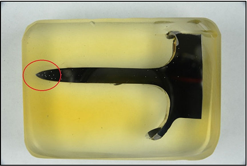
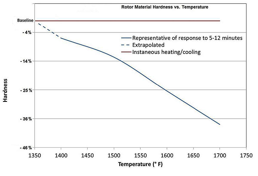
The analysis revealed that the readings for occurrence rotor hardness were lower than those quoted in the manufacturing specifications. The sign of lower-than-expected hardness indicates that the rotor section released from the occurrence engine had experienced an elevated temperature exposure that softened the rotor material. Tests demonstrated that, as the material is exposed to elevated temperature, the hardness drops. It should also be noted that this process takes some time, as exposure of small laboratory specimens to the various temperatures for short periods of time showed no appreciable drop in hardness. Laboratory samples exposed to elevated temperatures for between 5 and 12 minutes did exhibit an appreciable drop in hardness. This is exemplified by the rapid heat/cool curve of fully heat-treated material (Figure 18).
The bore section of the LPT1 rotor remained within the engine, hanging loosely around the rotor shaft, and was subsequently removed for analysis as part of the engine disassembly and investigation. It was photo-documented and subsequently sectioned for hardness evaluation. A cross-section of the LPT1 rotor section taken from the circumferential location that exhibited the greatest web necking indicated the point of rotor failure initiation and supported the conclusion that the rotor had been exposed to elevated temperatures.
In addition to LPT1, LPT2 and LPT3 rotors were removed and analyzed. Sections were taken from each of these rotors and, again, hardness tests were conducted to evaluate the potential for possible elevated temperature exposure. Hardness measurements from these rotors did not indicate any perceivable exposure to elevated temperatures.
A portion of the integral LPT2 brush seal land was found during disassembly of the occurrence engine. This seal land segment was reviewed in detail for the possible source of the failure. By matching the seal land segment with the LPT1 rotor bore section that fractured, it was determined that the seal land was struck by the LPT1 bore, which resulted in its failure. The radius of the LPT1 bore and the LPT2 brush seal land, and the condition of the 2 components, supported this hypothesis. Photo 11 shows the LPT1 bore and a section of the fractured LPT2 brush seal land. The geometry of the components and the localized condition indicate that the separated LPT1 bore struck and fractured the LPT2 integral brush seal.

1.16.3 Various debris analysis
MPE also assessed debris of various types to determine the source of the debris collected from engine components and from within the occurrence engine in the vicinity of the LPT1 and adjacent TIC during disassembly. The results of these various investigations indicated that some debris was metallic in nature and had indications of elements associated with rotor disk material. It was concluded that this debris could have resulted from rubbing immediately after the rotor failure and was not deemed to be associated with the initiation of the occurrence.
Other types of debris, such as scrapings and wipe samples taken from various components in the vicinity of the LPT1 and TIC components, were chemically analyzed. The results of this analysis indicated the presence of oil of the type used within the engine's bearing system. The solid residues showed indications of metallic oxidation and traces of phosphorus, which is a sign of charred oil on metallic components.
1.16.4 Characterization and analysis of the Teflon C-seal
Additional investigation efforts by Pratt & Whitney have focused on the Teflon C-seals used to seal the oil supply tubes within the TIC. The Teflon C-seal is produced by an outside supplier and is composed of a proprietary Teflon-based material with a metallic energizer spring.
The occurrence seal was initially used by Pratt & Whitney's Mechanical Systems group to replicate the tube and sealing system within the PW1500G engine for rig testing. Once this testing was completed, the occurrence seal was provided to MPE for validation of dimensional and thermo-physical properties. The dimensions of the occurrence seal, along with those of a new, unused seal, were assessed. Several dimensions of the occurrence seal were measured using optical photography and image analysis of a new seal. It was determined that the new seal conformed to the blueprint requirements defined by the supplier, but the occurrence seal had some dimensional differences. These dimensional differences indicated that the seal had acquired a permanent set due to growth in the axial dimension and reduction in diameter. The loosened fit of the seal to the housing led to the observed leakage.
Thermo-physical properties were measured on the supplier-provided new seal rings. Fourier transform infrared spectroscopy (FTIR) analysis was performed on a sample of a new Teflon C-seal. Results indicated that the seal sample was a direct match to specified material, with no additional materials detected.
FTIR analysis was also performed on the occurrence seal ring and compared with that of the new seal. The FTIR results showed a direct match between the new seal and the occurrence seal, meaning that the occurrence seal did meet the material specifications.
Thermo-mechanical analysis was performed on samples from the new and occurrence seals. The CTE was measured with this method, which indicated that a low-temperature reaction occurs in this material. The temperature of this reaction, which is presumed to be the glass transition temperature, was consistent between the 2 material samples, but the occurrence seal exhibited a marked, sharper step in the thermal expansion during heating through this low-temperature reaction.
Differential scanning calorimetry (DSC) was performed on new seal material. This analysis showed a higher temperature reaction, presumed to be the crystallization reaction, within this material. A single heating and cooling cycle was performed. The DSC analysis showed that the crystallization temperature for this material (608 °F) was consistent with expected temperatures resulting from a hot shutdown.
Aging studies were performed on samples of new seals at increasing temperatures to assess the impact of elevated temperature exposure on physical and dimensional stability of this seal ring material. The thermal exposure was performed using new seals installed on oil supply tubes, which were subsequently installed in production housings. The entire housing, tube, and seal assembly was heated to 515 °F in a furnace for 1 hour. This aged seal ring was then tested in Pratt & Whitney's Mechanical Systems laboratory to assess sealing performance. A second aging trial was similarly performed with new Teflon C-seals at 600 °F and 650 °F, consistent with expected temperatures caused by a hot shutdown. After the Mechanical Systems oil sealing testing, the aged seal rings were returned to MPE for assessment. The dimensions of these seal rings were measured. The aging process was shown to clearly change the dimensions and shape of the seal rings. It was demonstrated that, as the aging temperature increases, more permanent, inelastic deformation is observed. The configuration of the seals after aging and pressurization tests showed that they demonstrated increased distress and closure of the spring groove. The aging process clearly showed an impact on the shape of the side walls of the seal, with further aging showing the side walls pulling in around the internal spring.
From the material characterization of the seal materials, it was determined that the maximum temperature for sustained use is 500 °F, based on analysis of phase transformation temperatures, percent crystallinity, thermal conductivity, and dimensional stability. The seal material exhibits quantifiable changes at and above 550 °F. Material aged at 515 °F did not show a change in percent crystallinity, and leak testing was successful.
Laboratory tests were also completed to determine whether the oil-supply assembly, as installed between the TIC and the No. 4 bearing compartment in the engine, could demonstrate a leak. The occurrence engine tube joint was subjected to representative pressures, temperatures, and displacements in an attempt to reproduce a leak. Four room-temperature tests were completed with only negligible joint wetting observed. Four elevated-temperature tests were completed with higher levels of leakage observed. The highest level of leakage occurred during periods of increased tube-housing temperature difference. These findings support the primary hypothesis; however, it could not be determined whether the heat damage to the Teflon C-seal was the result of a single episode or the cumulative result of several high-temperature exposure periods .
To determine whether these results could be reproduced, laboratory tests, including simulating temperature-aged seals, were completed. Three different temperatures were selected for aging. A new oil supply tube and seal (installed in housing) were subjected to a seal-aging procedure (as previously described). The assembly was placed in an oven at 515 °F and aged for 1 hour. The oven was shut down while the assembly was allowed to cool. The tube assembly was then installed in the test rig, and the tube joint was subjected to representative pressures, temperatures, and displacements in an attempt to reproduce a leak.
For the unaged Teflon seal material, there was no leakage observed including the occurrence material, with all the loads applied (tube deflection, oil pressure, and temperature). The aged Teflon needed an initial pressure load to properly seat on the gland. This was demonstrated when the joint leaked a few drops of oil at room temperature at the beginning of the test. Once the seal was properly seated on the gland, the room temperature test was repeated and no leakage was observed. When heat was applied, and the temperature increased, the leakage first increased and then decreased to zero. This effect was due to the transient temperature increase causing the metallic gland to expand before the Teflon. Subsequently, the aged Teflon, which was slightly deformed due to aging and required additional time to fully expand, filled the gland and stopped the leak.
Testing at elevated temperatures was completed, and higher levels of leakage (similar to results from the occurrence engine oil supply tube) were observed. The highest level of leakage occurred during periods of increased tube-housing temperature difference. These findings demonstrated that results of the oil supply tube tests could be reproduced by exposing the seal to temperatures consistent with a hot shutdown.
1.16.5 Dimensional inspections
The dimensions of the occurrence engine housing were inspected at Pratt & Whitney's facility in Middletown, Connecticut. The inspection showed that some dimensions located in the highly heat-distressed area were slightly over or under the specified blueprint dimension. It is highly likely that the dimensions were out of tolerance because of heat damage. Some dimensions on the forward side, where the damage was minimal, were within specified dimensions.
The service tube bosses were also inspected, and the service tube's port inner diameters and true positions were measured. The inner diameters of all service tubes were found to be within specified dimensions, but the true position of these ports was not within blueprint dimensions. The service tubes were located in the area of distress noted at teardown. The true position's out-of-tolerance conditions were most likely caused by the occurrence.
The oil supply service tube and Teflon C-seal were also inspected. Measurements of the spring-energized Teflon C-seal were taken with a caliper without removing the seal from the tube after the tube was removed from the engine. The seal appeared to have decreased in diameter and increased in height. The seal was also measured after being removed from the tube, but it was broken during removal, which affected the reliability of the measurements. The dimensions of the seal groove of the occurrence engine's tube were measured with a caliper; no abnormalities were noted.
The tube had soot on the exterior. A scanning electron microscopy analysis was completed on the material and was deemed inconclusive for the presence of engine oil, but did show signs of a carbon-rich material and silicon–aluminum–oxygen, which is consistent with oil or carbon seal material and with the tube insulation.
1.16.6 Thermal analysis of No. 4 bearing compartment
The temperature environment of the No. 4 bearing compartment, where the No. 4 bearing oil supply tube resides, was originally evaluated in the fall of 2009, during the Pratt & Whitney engine development and certification phases, using a 2-dimensional (2D) ANSYS, Inc. finite element analysis tool, according to current engineering standard practices. Based on this 2D assessment, it was originally predicted that the Teflon C-seal would encounter soak-back temperatures below 500 °F in normal operational conditions.
The occurrence of a hot shutdown without a cooldown period was not considered in this assessment because the initial operating instructions called for a 10-minute cooldown period (below 70% N2) before shutting down in order to prevent a bowed rotor condition on the subsequent start and to ensure wall temperatures stayed below the temperature threshold for oil coking.
Following the occurrence, a thermal analysis of the No. 4 bearing compartment wall and supply tube boss temperatures was conducted using a current-generation 3-dimensional (3D) ANSYS, Inc. thermal model of the supply tube, including the tube fitting, bearing support, and TIC ID case. The thermal model was an extension of the 2D compartment model data, matched to actual compartment wall instrumentation data from a development engine.
In order to assess local Teflon C-seal temperatures, a 3D thermal sub-model was created integrating the TIC ID, the tube fitting, the No. 4 bearing support boss, and the bearing compartment into a sector model.
All air side thermal boundary conditions were consistent with the full TIC thermal model and validated air system analysis. All oil side boundary conditions were consistent with the validated wetted wall-compartment predictions.
A comparison of 2D and 3D models was then performed, and the results indicated that the upgraded 3D assessment yielded a maximum operational Teflon C-seal temperature exposure higher than previously estimated with the 2D model.
This 3D thermal model provided results consistent with the development engine's test data and confirmed that the radial seal could be exposed to temperatures higher than 640 °F during a hot engine shutdown if a post-shutdown cooldown procedure was not performed. The operational and normal soak-back temperatures affecting the Teflon C-seal were originally predicted to be below 500 °F, and the seal material was shown to exhibit quantifiable thermo-mechanical changes at and above 550 °F.
Significant progress was also made in using the new 3D model for the analysis of soak-back temperatures. However, to be able to conduct quick assessments or shutdown scenarios and to measure their impact on seal temperatures, a scaling procedure was derived that relates the data from a similar development engine's measurements of soak-back temperatures to a change in operating conditions, as expressed by compressor discharge temperature and oil supply temperature. The ratio between these temperature differences was experimentally determined in the course of testing the involved development engine for normal and hot shutdowns, respectively. A “hot shutdown” is defined as a zero fuel-flow indication condition (i.e., shutting off fuel) on a hot engine. A “hot engine” is one that has been operated at elevated power (>75% N2) and shut down without performing the engine shutdown procedure defined in the IOM or applicable RSI.
Pratt & Whitney reviewed the circumstances that could lead to LPT rotor overheating and identified only 2 possibilities: gas path ingestion or oil fire.
1.16.6.1 Gas path ingestion
Teardown results were unable to identify any of the failures that would lead to a reduction in TIC flow and/or pressure and allow gas path air to enter the rotor cavity. In addition, the failure scenario for gas path ingestion is not consistent with the occurrence. Owing to pressure and flow fields, gas path ingestion would be strongest at the blade root. The hot air would flow through the first blade root and toward the second stage rotor assembly; in this scenario, the area with the highest predicted distress would be the blade attachments of the first and second disk assemblies. The occurrence engine hardware did not exhibit distress consistent with this situation.
1.16.6.2 Oil fire
The remaining possible scenario was an event caused by an oil fire. In order to ignite and sustain a fire in the cavity, 3 elements must be present: oxygen for combustion, fuel to initiate and sustain a fire, and a source to ignite the mixture. As air is pumped through the engine to provide a cooling medium, oxygen is always present in the LPT cavity.
To determine whether an oil leak was the source of fuel to feed a fire, all of the bearing compartments were reviewed. Given the location of the distressed hardware, coupled with the condition of the bearing compartments, it was determined that the most likely source of oil was the No. 4 bearing compartment. Nineteen potential leak paths in the No. 4 bearing compartment were identified and reviewed, with the most likely source of any oil leakage being the oil supply tube. It was determined that the most likely source of oil was the tube interface, given the presence of soot and sign of burning in the TIC coupled with distress noted on the Teflon C-seal of the oil supply tube.
Three separate sources of ignition were examined: hot surface ignition, auto-ignition, and rubbing.
1.16.6.2.1 Hot surface ignition
Hot surface ignition can occur when the temperature of a contact surface is hot enough to ignite a source, typically a liquid. Analysis was completed to determine the susceptibility of the hardware configuration to hot surface ignition. The results of the analysis indicated that it is highly unlikely that hot surface ignition occurred in this case.
1.16.6.2.2 Auto-ignition
Auto-ignition is the spontaneous ignition of a vapour when the appropriate temperature and fuel pressure are present. Further analysis of auto-ignition indicated that there was insufficient pressure and temperature to create ignition at low power ranges; however, at higher power settings, conditions for auto-ignition were present in the torque box and LPT disk-face cavities. Therefore, it is likely that auto-ignition temperatures were reached at higher power settings during the occurrence engine ground run.
1.16.6.2.3 Rubbing
The occurrence hardware showed no sign of rub-induced sparking.
1.16.7 Oil scavenge capability
Insufficient oil scavenge capability was reviewed for potential contribution to the occurrence. Examination of the engine hardware did not identify any concerns with the capability of the oil scavenge system.
1.16.8 Bombardier damage assessment
At TC's request, a team of Bombardier engineers assessed the airframe damage to FTV1 resulting from the event. This damage assessment considered the structural and system damage induced by this rotor burst occurrence and evaluated the capability of the aircraft to continue safe flight and landing if the incident had happened during flight testing or operation. The damage to the aircraft's structure and system was evaluated against its failure effects on the aircraft-level functions, in accordance with the Aircraft Functional Hazard Assessment, as required by the certification program.
Bombardier's assessment concluded that, if the incident had occurred on the ground (before V1 [decision speed]) with a filled centre tank, it could have resulted in a fire hazard, and that if it had occurred on the ground (after V1), in the air or during landing, then the damage sustained would not have prevented continued safe flight and landing of the aircraft. Footnote 24
1.17 Organizational and management information
Not applicable.
1.18 Additional information
Not applicable.
1.19 Useful or effective investigation techniques
The fact that the occurrence aircraft was a flight test aircraft and that, consequently, it was equipped with an extensive array of data-gathering equipment, including numerous on-board synchronized video cameras, provided the investigators with valuable data in order to establish and understand the sequence of events with greater accuracy.
2.0 Analysis
2.1 Introduction
The flight crew was qualified and certified to conduct engine ground runs. The weather was not a factor. The analysis will focus on the engine cooldown procedure and the factors that led to the uncontained failure of the engine.
2.2 Engine cooldown procedures
From its initial release until the issuance of the engine's type certificate by TC, the Pratt & Whitney PW1500G installation and operating manual (IOM) specified a 10-minute cooling period before shutdown in order to minimize the potential for oil coking in the main engine bearing compartments and to mitigate a bowed rotor start condition. This cooling period was determined based on the results of testing carried out on development engines and demonstrated compliance with the PW1500G's certification basis.
The predicted temperature environment of the No. 4 bearing compartment, where the oil supply tube resides, was evaluated in the fall of 2009, during engine development and certification, using a 2-dimensional thermal analysis model, according to current engineering practices. The operational and normal soak-back temperatures that the No. 4 bearing oil feed tube's Teflon C-seal was expected to encounter in service were predicted to be below 500 °F. The effect of a hot shutdown was not considered at the time because the operating instructions required a 10-minute cooldown period before shutdown, which would have prevented the Teflon C-seal from being exposed to temperatures exceeding its design thermal limits of 500 °F.
After the occurrence, the thermal environment in the No. 4 bearing compartment was reassessed using a current-generation 3-dimensional thermal analysis model. This more accurate model confirmed that the Teflon C-seal could be exposed to temperatures greater than 640 °F during a hot engine shutdown.
The detrimental effect of heat soaking sustained during hot shutdowns on the bearing compartment tubes' Teflon C-seals was not foreseen by Pratt & Whitney during the development of Restriction and/or Special Instructions (RSI) No. F-500-001-71-011.
Between the original issuance of the RSI in July 2013 and the occurrence in May 2014, 7 shutdowns with a cooldown period of less than 5 minutes took place on the occurrence engine. Bombardier believed all of these hot shutdowns were in accordance with section 3.c. (original version) or 2.c. (rev.A) of the RSI, since the engine would not be restarted within 8 hours following the shutdown. One of those hot shutdowns, on 26 May 2014, was not in accordance with section 2.c. (rev.A) of the RSI because the engine was restarted before expiration of the 8-hour wait period (specifically, the restart occurred approximately 50 minutes after shutdown) and the indicated exhaust gas temperature at the time of the restart was above 90 °C (specifically, 99 °C).
In the absence of any indication in the RSI of potential damage to the engine when applying the mitigation technique, the RSI section 3.c. (original version) or 2.c. (rev.A), as written, was interpreted by Bombardier as an alternative equal to the other shutdown options contained in the RSI.
Therefore, applying the mitigation technique in section 3.c. of RSI No. F-500-001-71-0011 (or section 2.c. of rev.A), instead of those in sections 3.a. or 3.b. (or sections 2.a. or 2.b. of rev.A), led to the heat soaking on the No. 4 bearing oil feed tube's Teflon C-seal.
2.3 Effect of heat on Teflon C-seal
Testing of the occurrence Teflon C-seal's material revealed that its composition conformed to specifications. However, examination of the seal showed that its diameter and axial dimensions had been altered, and testing confirmed that the material began exhibiting quantifiable changes when exposed to temperatures above 550 °F, with permanent deformation beginning at 608 °F.
It could not be determined whether the heat damage to the Teflon C-seal was the cumulative result of several hot shutdowns or the sole result of the hot shutdown following the 21 May engine ground runs (Table 3). The high oil consumption first noticed on 26 May 2014 was likely the first apparent sign of severe oil leakage from the Teflon C-seal; however, the exact cause of the oil consumption had not yet been determined. It is also possible that an oil fire may have been present, perhaps sporadically, in the bearing cavity during the 26 May 2014 engine ground run and that the disk integrity had begun to be compromised (Table 3).
Testing demonstrated that, once the seal was compromised, oil leaked into the turbine intermediate case (TIC) and was drawn into the turbine rotor's cooling air stream. It is most likely that, sometime during the 74% N1 segment of the engine ground run, the temperature in the torque box reached the auto-ignition point of the oil, which generated a fire. This scenario is supported by the occurrence engine's teardown and subsequent laboratory analysis, which revealed the presence of soot and signs of burning in the torque box, clearly indicating that combustion had been taking place in the vicinity of the feed tube's mounting flange.
Rub-induced sparking and hot-surface ignition were also considered, but no sign of rubbing was found and analysis of hot-surface ignition concluded that it was highly unlikely to be the cause. Consequently, it was concluded that the air/oil mixture auto-ignited. The location and severity of thermal damage patterns on the TIC aft wall on the rotor cavity side were indicative of intense combustion between the TIC aft wall and the first stage rotor disk of the low-pressure turbine 1 (LPT1). The effect of the oil fire on the forward face of the LPT1 caused the rotor disk to be exposed to elevated temperatures, causing a softening of the disk material to the point where it failed in tensile overload. This was confirmed by laboratory analysis of a section of recovered rotor debris.
One or more hot shutdowns caused heat soaking, which allowed the oil feed tube's Teflon C-seal in the No. 4 bearing to fail, which in turn allowed engine oil to merge with the turbine rotor's cooling air stream. This air/oil mixture encountered ambient temperatures that were above its auto-ignition point, and the ensuing combustion heated the LPT rotor to the point of failure. The failure of the LPT rotor was uncontained and resulted in major damage to the engine, nacelle, and wing.
2.4 Survivability issues
2.4.1 Evacuation slide
There was no written procedure governing the arming configuration of evacuation slides during engine ground runs. Therefore, the arming configuration was left to the crew's discretion, and only the rear left passenger door was armed, which, in this occurrence, did not affect the speed of the evacuation. However, the evacuation could have been delayed in other circumstances if the door had been opened without the slide being armed beforehand. If all emergency evacuation slides are not armed before flight and engine ground runs, there is a risk that emergency evacuation of the occupants may be slowed or hindered.
2.4.2 Firefighting
In this occurrence, as the engine spooled down, the crew received several EICAS warnings and cautions, including L ENG FIRE DET FAIL and FIRE SYSTEM FAULT, but no fire indication was displayed in the cockpit. Despite being informed of the fire by the ground crew, the cockpit crew did not discharge the fire bottles. Although the detection system was rendered unserviceable, the fire extinguishing system was still functional and could have been activated to help suppress the fire. If the nacelle fire bottles are not deployed in the event of a fire, there is an increased risk that fire may spread beyond control.
The equipment trailer containing the wheeled fire extinguishers had been parked to the right and behind the aircraft, whereas the ground personnel were standing by in a vehicle parked to the left and forward of the aircraft. The first discharge of fire extinguishing agent by the ground crew occurred 2 minutes 28 seconds after the event. Had the equipment trailer been located closer to the personnel standing by, it would likely have permitted the ground crew to tackle the fire more rapidly. The unpredictability of such occurrences highlights the importance of the most rapid possible intervention in order to minimize the adverse consequences resulting from a fire outbreak.
If ground fire extinguishers are not located to permit quick access by the ground crew, there is an increased risk that a fire may spread beyond control.
3.0 Findings
3.1 Findings as to causes and contributing factors
- Bombardier interpreted Restriction and/or Special Instructions (RSI) No. F-500-001-71-0011 section 3.c. (original version) or 2.c. (rev.A), as written, as an alternative equal to the other shutdown options contained in the RSI. This resulted in the engines being exposed to one or more “hot shutdowns.”
- The hot shutdowns resulted in heat soaking beyond the design criteria of the No. 4 bearing oil feed tube's Teflon C-seal.
- The detrimental effect of heat soaking sustained during hot shutdowns on the bearing compartment tubes' Teflon C-seals was not foreseen by Pratt & Whitney during the development of Restriction and/or Special Instructions (RSI) No. F-500-001-71-011.
- Heat soaking caused the oil feed tube's Teflon C-seal in the No. 4 bearing to fail, which allowed engine oil to merge with the turbine rotor's cooling air stream.
- The resulting air/oil mixture then encountered ambient temperatures that were above its auto-ignition point, and the ensuing combustion heated the low-pressure turbine rotor to the point of failure.
- The failure of the low-pressure turbine rotor was uncontained and resulted in major damage to the engine, nacelle, and wing.
3.2 Findings as to risk
- If all emergency evacuation slides are not armed before flight and ground runs, there is a risk that emergency evacuation of the occupants may be slowed or hindered.
- If the nacelle fire bottles are not deployed in the event of a fire, there is an increased risk that fire may spread beyond control.
- If ground fire extinguishers are not located to permit quick access by the ground crew, there is an increased risk that a fire may spread beyond control.
4.0 Safety action
4.1 Safety action taken
4.1.1 Bombardier Inc.
Following the occurrence, Bombardier grounded the C Series test aircraft fleet until the cause of the occurrence could be clearly established.
4.1.2 Pratt & Whitney
Once the cause of the occurrence was ascertained, Pratt & Whitney proposed a plan to return to flight, which included:
- revised cooldown procedure, increasing the pre-shutdown cooling period to 20 minutes and requiring notification to Pratt & Whitney when there is a hot shutdown;
- the addition of a metallic face seal, in addition to the Teflon C-seal, on the No. 4 bearing oil feed tube mounting flange;
- a change in the material of the mounting bolts of the No. 4 bearing oil feed tube flange to enable higher torque on bolts;
- the installation of thermocouples to permit real-time monitoring of the low-pressure turbine (LPT) cavity temperature;
- operational restrictions to limit the oil seal temperature to 500 °F;
- post-flight daily oil consumption monitoring;
- operational restrictions in high outside air temperatures;
- increased daily borescope inspections.
These measures were implemented on an interim basis in order to return to flight testing.
Production engines will feature an enhanced design configuration for the oil supply tube and cooling airflow that will physically separate the turbine rotor cooling airflow from the bearing compartment to eliminate the possibility of recurrence.
This report concludes the Transportation Safety Board's investigation into this occurrence. the Board authorized the release of this report on . It was officially released on .