
Marine Investigation Report M05W0111
Loss of propulsion, subsequent striking of berthed pleasure craft and grounding
Roll-on / roll-off ferry Queen of Oak Bay
Horseshoe Bay, British Columbia
The Transportation Safety Board of Canada (TSB) investigated this occurrence for the purpose of advancing transportation safety. It is not the function of the Board to assign fault or determine civil or criminal liability. This report is not created for use in the context of legal, disciplinary or other proceedings. See Ownership and use of content.
-
Table of contents
Summary
At approximately 1008 Pacific daylight time on 30 June 2005, while approaching berth No. 1 at Horseshoe Bay, the Queen of Oak Bay suffered loss of propulsion and a reduction of steerage. As a result, the vessel deviated off course and struck 28 pleasure craft berthed in the adjacent marina before running aground. There were no casualties; however, there was considerable damage to the pleasure craft and marina.
1.0 Factual information
1.1 Particulars of the vessel
| Name of vessel | "QUEEN OF OAK BAY" |
|---|---|
| Official number | 396065 |
| Port of registry | Victoria, B.C.Footnote 1 |
| Flag | Canada |
| Type | Double-ended roll-on/roll-off ferry |
| Gross tonnage | 6969 |
| LengthFootnote 2 | 139.35 m |
| Draught | Forward: 5.5 m Aft: 5.5 m |
| Built | 1981, Victoria, B.C. |
| Propulsion | Two MaK diesel engines, type 12 M551 AK, 11 860 BHP, driving two controllable-pitch propellers (one at each end of the vessel) |
| Capacity | 1442 passengers and crew, 360 vehicles |
| On board | 544 passengers, 36 crew members, 76 vehicles |
| Owner/manager(s) | British Columbia Ferry Services Inc. (BC Ferries), Victoria, B.C. |

1.1.1 Description of the vessel
The Queen of Oak Bay is a double-ended vessel having a wheelhouse, a controllable-pitch propeller and a rudder at each end, and the engine room at midships. The two ends are almost identical and, for the purposes of identification, are numbered 1 and 2. This establishes the port and starboard sides of the vessel and the numbering system of the machinery in the engine room (see Figure 1).

The vessel is equipped with one anchor (along with the associated windlass, power unit, and controls), which is housed in a separate dedicated compartment located on the starboard forward part of the main car deck, at the No. 1 end. (When the ferry is sailing with its No. 2 end forward, the anchor is located at and deployed from the vessel's port quarter.) The compartment can only be entered via a door that is normally kept closed. Releasing the anchor is accomplished by removing its securing device and then taking the tension off the windlass brake.Footnote 3
The engine room contains two main propulsion engines, three auxiliary engines for electrical power generation, and their associated machinery and equipment. Two propeller shafts and intermediate shafts connect the main engines to the propellers via reduction gears.
An engine control room is located within the engine room, on the port side.Footnote 4 It contains the main electric switchboard and the means to remotely start, stop, and monitor the main engines and associated machinery. The engine control room's inboard side is fitted with windows, and both main engines are partially visible.
1.1.2 Engine room and wheelhouse manoeuvring stations
The engine room manoeuvring station is located in the engine control room and contains the telegraphs and the engine-speed levers, along with pneumatic controls to engage/disengage the clutches, stop the main engines, and change control between the engine room/wheelhouse. Gauges for monitoring the propulsion plant, as well as alarm panels, are also located there.
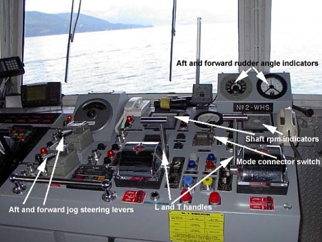
Each wheelhouse has a manoeuvring station forward of the steering console, providing the operator with an unrestricted view forward. Like the engine room station, the telegraphs and the engine-speed levers are located there, as are pneumatic selector switches for changing between the two wheelhouses and the two modes of vessel operation. The two engine/propeller pitch-control levers have differently shaped handles: the T-shaped handle, corresponding to the stern propeller, is situated on the right-hand side; the L-shaped handle, which controls the forward propeller, is to the operator's left (see Photo 2).
The steering wheel in each wheelhouse controls the corresponding stern rudder; thus, the wheel in the No. 2 end wheelhouse controls the No. 1 end rudder, and vice versa. As a rule, the steering wheel is used by a helmsman to make course alterations while the ship is on passage. A wheelhouse can also control the corresponding bow rudder by means of a jog steering lever on the manoeuvring station. Another jog steering lever, located above the one for the No. 2 rudder, controls the No. 1 rudder.
The two jog steering controls are used during berthing operations, when increased manoeuvrability is required. In such instances, the master uses both the two pitch-control and two jog steering levers in combination.
1.1.3 Two modes of propulsion
There are two main engines, each with two pneumatic clutches; the combination yields two ways to operate the propellers. Propeller pitch can be varied, and the main engines operate between 325 and 450 rpm. Vessel speed is controlled by a pneumatic combinator connected to the speed-control lever; this automatically varies propeller pitch and engine rpm (see Figure 2 for modes of operation).
Mode 1
All power generated by the two main engines is used by one propeller. This mode is used when the vessel has finished manoeuvring and is under way on passage. Only the stern propeller is used; this is done by engaging clutches 1A and 2B or 1B and 2A.
Mode 2
All four clutches are engaged, providing power to both propellers. This mode is primarily used during berthing and unberthing. The amount of power absorbed by each propeller can be varied by adjusting the blade pitch, but the default is a ratio of 70:30 or 60:40, with the forward propeller taking the lesser amount, because it is used to slow the vessel.
In both modes, the two main engines are mechanically coupled, effectively behaving as a single unit. There is no automatic means to isolate them in the event of a fault in one; any change in the operating condition of one is automatically, and instantaneously, reflected in the other.Footnote 5
Various other combinations of engines/clutches/propellers are also possible from the control station in the engine control room, and either engine can provide power to either propeller.
1.1.4 Mode selection switches on the control consoles
Under normal circumstances, the vessel is manoeuvred and the engine rpm and the propeller pitch are controlled from the wheelhouse. The wheelhouse console has one pneumatic switch for changing modes. There are no indicators to show if the command given by the switch has been correctly executed and how many, or which, of the four clutches have been engaged. An operator in the wheelhouse can ascertain clutch engagement only by looking at the propeller shaft rpm indicators on the same console (see Photo 2).
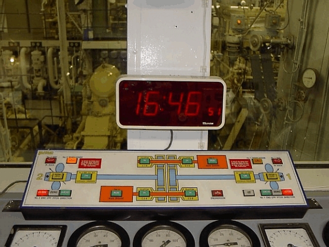
Lights on the engine control room console indicate which of the four clutch-control switches are engaged. A mimic board continuously displays the status of the clutches, main engines, propeller pitch, wheelhouse in use, etc. (see Photo 3), allowing engineers to always see the operational conditions of the clutches and the propulsion plant.
In the event of a malfunction, neither the engine control room nor the wheelhouse has a direct, audible alarm to alert operators to an accidental or inadvertent disengagement of one or more clutches.
1.1.5 Description of a typical berthing and unberthing manoeuvre
After ringing "stand by" at the end of a full-speed passage, the master begins slowing the vessel. As propulsion is still in Mode 1, this is done by using the T-shaped speed-control lever. At an appropriate time, the master switches over to Mode 2 and, now that the forward propeller also has power, uses the L handle to vary rpm and pitch, slowing the vessel's forward progress. This is achieved by operating the forward propeller in its ahead-thrust direction. (Both the forward and stern propellers are thus turning in their respective "ahead" direction.)
During berthing, the stern and forward rudders are controlled by their respective jog steering levers. The force of the wash created by the propellers acts upon the rudders, causing the vessel's bow or stern to swing in the required direction. Placing the forward jog steering lever to port, for example, makes the bow swing to port.Footnote 6 In these circumstances, the forward rudder's function is similar to a bow thruster. This is very important for safe manoeuvring, particularly in rough weather.
Once in the berth, the propulsion system remains in Mode 2 and the forward propeller is set to a slight astern pitch, while the stern propeller is set at a slightly forward pitch.Footnote 7 Both propellers thus develop a little forward thrust, pushing the vessel against the dock.
To unberth, manoeuvring control is transferred to the opposite wheelhouse. The forward propeller becomes the stern propeller, providing thrust for the ferry to move forward. Once the ferry is clear of the berth, the system returns to Mode 1.
1.2 History of the voyage
At the time of the occurrence, the Queen of Oak Bay was based at Horseshoe Bay, B.C., and employed on the Departure Bay-Nanaimo, B.C., route. On 30 June 2005, the ferry started its scheduled run at 0624 Pacific daylight time.Footnote 8 A single 30-nautical mile crossing takes about 95 minutes, and the ferry made the first crossing without incident. At 0834, the vessel left Departure Bay in occasionally foggy but calm conditions, on its second trip of the day, with 544 passengers, 76 vehicles, and 36 crew members on board. It arrived at Lookout Point at 1002. During the crossing, the main engines were operating in Mode 1 and, via clutches 1A and 2B, were supplying power to the stern propeller. The ferry usually berths at the No. 2 berth at Horseshoe Bay terminal, but was assigned the No. 1 berth because the No. 2 was occupied by the Queen of Coquitlam. The No. 1 berth is adjacent to Sewell's Marina.

At 1002, the master placed the engine room on "standby" for arrival at Horseshoe Bay and at 1005 changed over to Mode 2, engaging all four clutches. The vessel was lined up for the centre of the No. 1 berth, but at 1008, while about 200 m away from the floating leads, all propulsive power was lost. Seeing that the propellers had stopped turning, the master telephoned the engine room, informed them of the power loss, and ordered the engines to be restarted and power restored.
In the engine room, the engineers could see that the clutch-control levers were still in the lock position but that the clutches themselves had become disengaged and that the No. 1 main engine had stopped while the No. 2 was still running, apparently at its idling rpm. Various alarms had also triggered. The engineers tried to restart the No. 1 main engine to restore power.
Repeatedly sounding the vessel's whistle, the master called for the anchor to be deployed, but the anchor station was not crewed; consistent with onboard practices, the deckhand whose designated duty was to release the brake in an emergency was performing other duties elsewhere on the vessel. The anchor was not released.
An imminent impact was announced, and passengers were instructed to brace themselves.
Under the influence of the last starboard helm input to keep the vessel aligned with the dock, the vessel slowly turned to starboard towards the marina, and the master gave orders and corrective port helm was applied. With the approach speed of three to four knots, the port rudder did not take effect and the ferry continued on its starboard heading, striking a number of boats in the marina before running aground on the seabed and coming to a stop.
There were only a few people on jetties and in boats at the marina at the time of the occurrence; there were no casualties.
1.3 Damage
The vessel suffered minor damage to the No. 2 propeller and some scraping damage to its hull. There was extensive damage to the marina and 28 pleasure craft moored there.
1.4 Speed regulation of the main engines
The operating range of the main engines is between 325 and 450 rpm, and speed and loading can be varied by the speed-and pitch-control levers in the wheelhouse or in the engine control room. Each engine has a hydraulic governor that serves to keep the rpm constant. The governor also keeps the rpm steady, reacting to changing external conditions - wind, weather, seas, vessel movements - that affect the loading on the engine.
Input signals to the governor are pneumatic, whereas the output shaft of the governor is mechanically connected to the fuel racks. In response to the input signal, the governor directly controls the fuel racks, increasing or decreasing the fuel injected into the cylinders so as to keep the rpm within fixed limits.
Each engine has two banks of six cylinders, arranged in a V. Each cylinder has a fuel pump, the fuel rack of which is connected to a common shaft running the length of the engine. Another shaft runs transversely across the engine and, via linkages, connects the two common shafts to the governor's output lever. Connection between the governor output shaft and the engine shafts, levers, and linkages is via steel pins and castellated nuts, with positive tensioning ensured by split pins fitted through the pins and nuts. The drive for the governor is taken off the engine's camshaft and mounted at its power take-off end. Four foundation bolts secure the governor to the engine.
Rotary motion of the governor output shaft is transmitted to the common shaft and converted at the fuel pump racks. Various stops and condition-monitoring sensors are connected to the common shafts; these include an engine overspeed trip, a fuel rack position indicator, and a manual emergency shutdown.
In the event of a failure, there is no arrangement within the fuel-regulation mechanism to return the fuel racks to zero, nor is this a regulatory requirement.
1.4.1 Post-accident faults found on main engine fuel and governor linkages
After the accident, inspection of the linkages on the two main engines revealed the following:
A castellated nut on the link pin for connecting the governor's output lever on the No. 1 main engine governor's output shaft to a control linkage was found on the floor plates beneath the governor. The linkage had slid out of the governor's output lever link pin, causing the governor to become disconnected from the engine's fuel control rack linkages (see Photo 4).
No broken pieces of the locking split pin were found in the vicinity of the nut, nor were any left behind in the bore of the link pin or the nut.
The orientation of the fitted link pin was contrary to that indicated in the manufacturer's drawings, which indicated that the pin was to be inserted with its head on the side of the link rod, with the nut lying on the outer side of the output lever. There was no indication that the orientation of the pin would have resulted in a detrimental effect or condition.
The link pin was designed to slide into its designated bored hole in the output lever. Wear from usage created an excessive clearance between itself and the bored hole.
The link pin and nut assembly on the No. 2 main engine was found to be different from that on the No. 1 engine and not of the manufacturer's supply. It had been fabricated out of hexagonal bar stock, and its locking arrangement was by means of a spring lock washer under a regular hexagonal nut, instead of a split pin. Its thread was from the ½-20 UNF series. Testing revealed excessive play between the bolt, flat washers, lock washer, and nut.Footnote 9 The method of locking the nut was found inappropriate for this type of application.

Some linkages had been assembled so that they lay at an angle to other linkages and rods, rather than at right angles. The linkages incorporate spherical joints that allow a degree of misalignment. The angles formed were sufficiently large as to place a small amount of bending moment on the link rods, instead of the pure tension and compression required by their design; this was not significant enough to cause any damage.
Another link pin connected to the output shaft of the governor on the No. 2 main engine was found bent and damaged. This linkage from the output shaft of the governor provides a signal to the pitch controller as well as to the fuel rack position indicator in the control room. This was deemed to be a pre-existing condition because there are no significant couples acting upon the linkage for the damage to have occurred as a result of the engine's overspeeding.
1.4.2 Description of linkages on main engine and governors of other vessels
The Queen of Oak Bay has four sister vessels. Of these C Class vessels, the Queen of Surrey and the Queen of Coquitlam were inspected. The main engines and arrangement of the governors on the Queen of Surrey were found similar to those on the Queen of Oak Bay, and some linkages had been assembled so that they lay at an angle - instead of perpendicular - to other linkages and rods.
The governor's output lever has a number of drilled holes for fitting the connecting pin. On both vessels, the pin was fitted in one of the bottom holes. Locating it in an upper hole would increase the moment produced by the output shaft, enabling the governor to produce less torque to move the fuel racks. The total radial travel of the output shaft and the corresponding linear travel of the fuel racks would also increase; this would also increase the sensitivity of the governor and the potential for the engine to hunt. Selection of the optimum location of the pin is done at the time of the initial setting up of the engine, or after major component renewal or overhaul.
1.5 Protection devices on the main engines
Protection devices are fitted on all engines to safeguard against abnormal operating conditions. These devices can be alarms that are triggered at pre-set values, or switches that automatically shut down the engine if an abnormality is not rectified.
The main engines on the Queen of Oak Bay are fitted with two kinds of instant shutdowns - an automatic overspeed protection device and a manual emergency stop. In the event of low lubricating oil pressure, high cooling-water temperature, or other such irregularity, an alarm is set off and a watchkeeping engineer may choose to activate the emergency stop. This works through a pneumatic cylinder, which upon activation, trips a latch and releases a spring that pushes the fuel racks to zero. After the engine has stopped, resetting the overspeed trip requires turning it with starting air for one complete revolution to reset the pneumatic cylinder. To reset the pneumatic cylinder after a manual shutdown requires setting the controller to the normal position.
To prevent the faulty engine from dragging the other engine with it, and to shut down safely, as soon as the fuel racks reach zero, a micro-switch is triggered, which in turn sends a signal to disengage the clutch as the engine shuts down.
The engines do not have automatic emergency shutdowns corresponding to low lubricating oil pressure or high jacket cooling water temperature nor were they required by regulations.
1.6 Mid-life upgrade
The Queen of Oak Bay was built in 1981, and, in order to renew and repair many of its facilities, underwent a mid-life upgrade (MLU) in 2004-2005 at the shipyard, Vancouver Drydock Company. The work was done by the shipyard and various suggested sub-contractors. Prime Mover Controls is one of these contractors. The shipyard set up an independent project office, under the charge of a project manager, to organize, execute, supervise, and test the repairs.
Included in the MLU were:
- surveys, planned maintenance, and repair items for machinery and equipment in the engine room and deck;
- an overhaul and servicing of the main engine governors and the pneumatic control system; and
- re-calibration and replacement of many analog engine control room gauges with digital ones.
1.6.1 Work generation, tracking, and control
The vessel uses a PC-based software application for planned maintenance, its equipment database, inventory control, work-order generation and, at the time of the accident, inter-watch communication. After repair lists were drawn up, discussed with management, and finalized, engineers entered the items in the software application and generated work-order numbers for them.
1.6.2 Crewing and watchkeeping
A ferry is crewed by personnel attached to the terminal to which the ferry is assigned. When a ferry such as the Queen of Oak Bay is operational, it has four watches of engineers assigned to it; three watches actively work on the vessel while the fourth is on its days off. There are three duty periods, or shifts: a morning shift, an afternoon shift, and a night shift. The morning and afternoon shifts are under the charge of either the senior chief engineer or a chief engineer; the night shift is under the charge of a first engineer.
During the MLU, the shift system was suspended and work was done by day workers. The senior chief engineer worked from 0600 to 1430, and the chief engineer worked from 1415 to 2300. Both had appropriate junior engineers to assist them. Weekends and night shifts were not worked. A 15-minute overlap enabled handovers.
The MLU began on 15 November 2004 and ended on 30 May 2005. When the MLU was being planned and also during its first few months, until mid-January 2005, the Queen of Oak Bay was assigned to Departure Bay, Nanaimo, and was crewed by people attached to that terminal. The repair lists were drawn up by this crew and most of the repairs and renovations were either started directly by them, or assigned to contractors at this time.
In December 2004, BC Ferries management assigned the Queen of Oak Bay to Horseshoe Bay. Responsibility of the vessel and oversight of the MLU project thus transferred from the Nanaimo-based crew to the Horseshoe Bay-based crew. As the MLU would now have to be done by a new crew, it was decided to allow some time for the new (Horseshoe Bay) senior chief engineer to familiarize himself with the project, so as to maintain continuity. Accordingly, he joined the vessel on 04 January 2005 and, for the next two weeks, was familiarized with the work being done. After two weeks, the crews changed over, though the previous senior chief engineer remained attached to the MLU and maintained regular contact.
1.6.3 Procedure for repairing the governors
It is BC Ferries' practice to send governors to an authorized specialist, Prime Mover Controls, for periodic overhaul or when they break down. Either vessel staff, or the contractor and sub contractor would disconnect the governor from the engine, and make arrangements for the governor to be shipped for repairs. After servicing, governors are tested and adjusted on a test bench that duplicates actual engine parameters. The governors on some BC Ferries vessels are subsequently reconnected and the engines run up with Prime Mover Controls verifying the governors' settings, calibrations and operation. This is not normally the case for C Class vessels; however, the MLU was an unusual event.
On 20 January 2005, both of the vessel's governors were disconnected from the main engines. Technicians representing Prime Mover Controls, who happened to be in the engine room at that time, then took them to their workshop. The contract issued by BC Ferries to the Vancouver Drydock Company specified that the shipyard was to remove and re-install the governors, and that the governors be shipped to Prime Mover Controls to perform the overhaul. Written records lacked detail, and other information gathered during the investigation was unable to confirm who actually performed the work in this instance.
At the request of vessel staff, Prime Mover Controls returned to the vessel on 23 June 2005 to investigate a reported engine hunting problem; this included adjustments to the No. 1 main engine governor.
1.7 Description of post-repair sea trials
Following the accident, on 06 July 2005, the Queen of Oak Bay was taken to sea for post-occurrence sea trials, where various main engine operational conditions and shutdown scenarios were simulated. The main findings included the following:
- The overspeed trip for the No. 1 main engine was set at 524 rpm.
- The overspeed trip for the No. 2 main engine was set at 511 rpm.
- With the No. 2 main engine running and the No. 1 main engine stopped, the governor on the No. 1 main engine was disconnected from its fuel-control linkages. No consequent movement was observed on the fuel racks.
- With the No. 1 main engine running and the No. 2 main engine stopped, the governor on the No. 2 main engine was disconnected from its fuel-control linkages. No consequent movement was observed on the fuel racks.
- The two fuel control racks for A and B banks of the No. 2 main engine were not set equally. When the engine was stopped by its overspeed trip, the B bank fuel pump racks were at zero, but the A bank fuel pump racks remained at approximately 10 mm.
- With propulsion control set in Mode 2, that is, both main engines clutched in and thereby coupled together, the No. 1 engine was manually speeded up. This caused the No. 2 engine to speed up instantly, and its governor output shaft moved to reduce fuel racks to zero.
- Average time for clutches to disengage when the engines tripped on overspeed was found to be five seconds.
1.8 Safety management system and fleet regulations
Although not required to comply with the International Safety Management (ISM) Code, BC Ferries has elected to do so. It obtained a document of compliance for its fleet and a safety management certificate for the Queen of Oak Bay in 1995. Safety management systems (SMSs) had been developed for all BC Ferries vessels and safety management certificates obtained for them. The issuing authority for the document of compliance and the safety management certificates is Lloyd's Register North America, Inc.
In order to ensure continued compliance with ISM requirements and to maintain validity of its document of compliance and safety management certificates, BC Ferries management as well as all BC Ferries vessels underwent periodic renewal and verification audits by Lloyd's Register.
The SMS for the Queen of Oak Bay required, amongst other things, the drawing up and implementation of vessel-inspection and planned-maintenance routines, effective document control, internal and external communications, contingency plans, and procedures for dealing with various potential shipboard emergencies.
As part of the SMS, BC Ferries has developed a Fleet Regulations policy and procedures manual. The Fleet Regulations manual took effect in March 2005. It formalizes all BC Ferries policies, and is to be used as a reference.
1.8.1 Inspection and planned maintenance procedures
In addition to annual inspections and servicing of critical control systems by competent professionals, engine room watchkeepers were required to periodically inspect the engine room and the main and auxiliary engines. Items to be checked by engine room watchkeepers, and the nature of these checks, were specified in checklists drafted pursuant to the ship's SMS and Fleet Regulations manual. Inspection of the main and auxiliary engine governors and fuel linkages was required before morning startup and at regular intervals thereafter. Incoming watches were also required to do this, and ensure proper functioning of all machinery before beginning a shift.
As checklists for engine room operations cannot enumerate every detail, the watchkeeping staff was also required to use their experience, knowledge, and training to advantage.
According to the SMS, planned maintenance routines required the main engines to be dismantled and overhauled on the basis of running hours, with different routines established for different components. The work was performed by ship staff or shore-based contractors. Neither the engine manufacturer, the company management's engineering department, nor the vessel's senior engineers had specified planned maintenance routines for the inspection or renewal of the governor's output lever or link pin following a safety-critical maintenance task.
1.8.2 Internal communications and record keeping
During the MLU, most communication between the two different shifts of engineering crews, the project manager and his team, and the shore contractors was verbal. The ship's engineering staff kept daily progress records of all work in the engine room, making suitable entries on the PC-based software application's watch log report page. Another section of the software application deals with planned maintenance, and contains an engineering history of different items of the ship's machinery.
The SMS requires that records be maintained for many of the vessel's activities, including machinery operations and maintenance. Neither the watch log report nor the planned maintenance records are controlled documents as defined by the SMS and the Fleet Regulations manual; however, they are kept for two years.
The watch log report pages show that the two governors were disconnected from the main engines, removed from the vessel, and then received back on board, but neither the watch log page nor the individual equipment database indicates the specific work carried out - nor do they indicate who reconnected them back onto the engines, or whether any problems were experienced during refitting and the subsequent engine run-up.
1.9 Vessel and crew certification
The Queen of Oak Bay was certified, equipped, and crewed in accordance with existing regulations. Additionally, BC Ferries and the vessel voluntarily held valid certification in accordance with ISM requirements.
2.0 Analysis
2.1 Loss of propulsion
The function of a governor is to limit an engine's rpm around a set point, preventing it from overspeeding. As the castellated nut loosened under vibrations, the control linkage fell out. This allowed the No. 1 main engine's governor to become disconnected from its fuel-control racks, leaving the engine without speed control. Neither the engine fuel-control shafts nor individual fuel pump racks were fitted with return springs (nor were they required to be). Therefore, overspeeding of the engine could not be prevented because the fuel racks could not be brought back to zero.
The engine was stopped by its overspeed protection trip. This could have been activated when the engine sped up as its fuel racks moved towards full fuel admission. However, when simulated during the sea trials (by disconnecting the governor of an engine), the fuel racks did not move in either direction.
The trial conditions, however, did not exactly mirror those at the time of the accident; the engine being tested was not running, nor had it warmed up to the same extent. Since this is a 60° V engine, the fuel racks are inclined 30°. It was expected that, under the influence of gravity and induced vibrations from all the running machinery, the fuel racks would move downwards, towards full fuel admission. Although this did not happen in the test case, it is still possible that, had the simulated conditions been identical, the racks may have moved downwards towards full fuel and caused the engine to overspeed.
A more likely scenario is that, as the vessel was engaged in manoeuvring operations, the load on the engines was being constantly reduced by the navigating officers. It is possible that the governor became disconnected just as the pitch of the propellers was reduced. As shown in the simulation, the fuel racks would not have moved, thus the quantity of fuel being admitted into the cylinders remained unchanged, but the load on the engines dropped sharply. This reduction in load, without a corresponding reduction in fuel injected, caused the engines to rotate faster and eventually trip on overspeed.
The vessel was in Mode 2 operation, and since the two engines were coupled together, the increase in the No. 1 engine's rpm also caused an immediate and corresponding increase in the No. 2 engine's rpm. The No. 2 engine's overspeed trip was found to be set at 511 rpm and the No. 1's at 524 rpm; the No. 2 engine thus tripped first, followed closely by the No. 1 main engine, the entire shutdown scenario probably taking no more than a few seconds.
As verified in post-accident trials, the governor on the No. 2 engine - sensing the increasing rpm - would have moved to reduce the fuel input into the engine. The interconnection of the two engines would have caused the No. 1 engine to take the No. 2 engine with it, even if the governor had reduced fuel admission to zero.
The activation of both the overspeed trips would have sent a signal to the clutches, causing them to declutch. This would not have been indicated on the wheelhouse console, where the control switch would still be in the forward and aft propeller position (Mode 2).
The No. 2 main engine continued to run in spite of having tripped on overspeed because, even though the overspeed protection device had pushed the fuel-control shafts to zero, the fuel pump racks on the A bank side had been improperly calibrated and remained set at a stroke of about 10 mm. This was sufficient to allow the engine to keep turning over, but not enough to let it take any appreciable load. The declutching of the engine also removed its connection with the propellers, further reducing all applied load.
The absence of a split pin on the securing nut on a governor linkage of the No. 1 main engine thus caused the governor to become disconnected from the fuel racks. The two main engines were interconnected at this time, and this caused the overspeeding No. 1 main engine to drag the No. 2 main engine into a shutdown condition with it, leaving the vessel without propulsion.
The Queen of Oak Bay's speed at this time was three to four knots. Without the propellers providing a wash over the rudders, this was too low a speed to enable steerage, and the vessel's heading could not be altered.
2.1.1 Absent split pin on the securing nut of the governor link pin
Reconnecting the governor to the main engine requires placing it on its stand, aligning the drive gear and then tightening the four securing nuts. The link arm on the governor output shaft is then connected to the linkages of the fuel-control shafts. A split pin fitted through the castellated nut secures the linkages to the governor's output lever link pin.
The Queen of Oak Bay finished its MLU on 08 June 2005. Less than a month later, the nut worked itself loose and fell off. In order for this to occur, the locking split pin that is used to secure the nut was either not fitted or was fitted improperly.
Supervision or verification is essential to ensure that assigned work is completed properly, irrespective of whether the work is done by ship staff or contractor. This is crucial when safety-critical components of an engine are not readily visible under routine operations. The fact that the problem with the split pin was not detected would indicate that supervision/verification of the work was ineffective at all levels.
2.2 Engine shutdown and the effect on interconnected engines
2.2.1 Overspeed shutdowns
The two main engines are clutched together in both Mode 1 and Mode 2, effectively making them one entity. A speed change in one engine instantly causes a corresponding speed change in the other, and an overspeed shutdown of one will cause the other to shut down.
This is because the engines have similar operating revolutions and therefore similar overspeed trip settings.Footnote 10 The tripping devices work by cutting off the fuel to the engine, but because they are of mechanical design, there will be a difference of a few revolutions between the two engines' settings. Assuming that the overspeed shutdown setting of one is at 520 rpm and the other at 524 rpm, this creates two shutdown conditions:
- If the 524 rpm engine starts to overspeed, it will drag the 520 rpm engine with it. Both will shut down.
- If the 520 rpm engine starts to overspeed, because of the inertia of rotating parts, it would in all probability go past 524 rpm even after its fuel supply has been cut off. It could then, in low-load conditions, drag the 524 rpm engine into an overspeed condition, causing both engines to shut down.
If the trips on both the engines are set to the same value, overspeeding by either engine will cause the other to shut down.
This condition of the good engine also shutting down occurs because the same overspeed sensor is used to send a signal to both the overspeed shutdown cylinder and the declutching cylinder.
2.2.2 Shutdowns caused by other fault conditions and design of the stop switch
BC Ferries is operating four other vessels with similar propulsion features as the Queen of Oak Bay. Inherently, these vessels have redundancy in propulsion power in that they are fitted with multiple engines, shafts, and propellers. It is not uncommon to have two or more engines clutched to common propulsion shafting. However, their configuration should be such that fault conditions on one engine are not allowed to detrimentally influence the other engine(s) in the propulsion system.
These fault conditions may include
- engine overspeed,
- low fuel pressure,
- low scavenge air pressure,
- high operating temperature,
- low lubricating oil pressure, and
- control failure.
Some of these fault conditions are monitored by the engine room alarm system, which will trigger an alarm. However, on the C Class vessels, only engine overspeed is connected to an automatic engine shutdown device. For all other faults, it is up to the engineer to stop the faulty engine using the manual emergency stop switch before it causes the other interconnected engine to stop.
The manual emergency stop switch sends sequential signals for declutching and stopping the engine. Notwithstanding, once an engineer hears an alarm and initiates a manual shutdown, it takes five seconds for the clutches to disengage, during which time the faulty engine is slowing down because its fuel supply has been shut off. However, in the event that one of the above fault conditions occurs and the faulty engine's clutch is still engaged, the faulty engine increases the load on the good engine. The control system on the good engine tries to maintain the set rpm, and consequently sensing the load from the faulty engine, the governor on the good engine moves the fuel racks, increasing the amount of fuel. When the clutches connected to the faulty engine are finally disengaged using the manual shutdown, the load imposed by the faulty engine is removed and the governor on the good engine may not be able to pull back the fuel racks in time to prevent the good engine from overspeeding and also shutting down.
On 13 and 14 February 2007, BC Ferries conducted trials aboard the Queen of Surrey to test the possibility of this scenario. The two main engines were put in Mode 2 operation and loading conditions existing during a docking were simulated. Under these conditions, it was found that, when the manual emergency stop was activated to shut down one main engine, it disengaged safely and did not bring about a shutdown of the other running interconnected engine.
The sea trials, however, were conducted at relatively low engine speeds and did not simulate the response of an engine operating in the upper rpm and load range, when a faulty engine suddenly declutches.
It is still possible that there are fault conditions that may require a main engine on the C Class ferries to be shut down quickly for which automated isolation from the other connected engine has not been incorporated, thereby placing at risk the vessel, passengers, crew, and the environment.
2.3 Evaluation of emergency situations
Wheelhouse manoeuvring consoles on C Class ferries do not have a mimic board showing the propulsion plant's condition. Relying on the propeller rpm gauges may therefore be misleading and, without gauges to likewise indicate engine rpm or the position of the clutches, it is impossible to tell if an engine is declutched but running, idling, or fully stopped.
At 1008, when the Queen of Oak Bay lost all propulsive power, the wheelhouse crew did not know that the clutches had become disengaged and that the No. 2 engine was still running. They could only see that both propeller shafts had stopped turning, and so they telephoned the engine control room and, without knowing the status of the propulsion plant, ordered the engine crew to restart the engines. The order, therefore, distracted the engine crew from effectively evaluating the nature of the failure.
In an emergency situation, decisions must be made taking into consideration all available information. Otherwise, subsequent actions intended to resolve the situation may be ineffective, thus placing the vessel at risk.
2.4 Safety management system
2.4.1 Internal communications and record keeping
Given that ferries change operating routes and terminals, are crewed from different pools, and their system of rotational watchkeeping does not enable direct communication between different shifts, it is crucial to ensure an accurate and detailed information exchange.Footnote 11 The exchange of appropriate operational information improves operational efficiencies, optimises utilization of resources, improves performance, and helps to minimize errors. It also provides a historical account of the performance and repair records of both personnel and machinery. Additionally, this enables effective gauging of staff capabilities, and performance trend monitoring and preventive maintenance of equipment - all of which are required by the ISM Code, the vessel's SMS and the company's Fleet Regulations.
The watch log report page in the software application for planned maintenance is the primary means to store and pass pertinent information from watch to watch on all BC Ferries vessels, and also from shift to shift, crew to crew, and ship to superintendent's office. It contains information about work completed during a watch, and details of work not yet done. This page, however, is not a controlled document; beyond requiring the identification of the person making the entry, his/her shift, and the date, there is no set format. Furthermore, there are no instructions from BC Ferries management or the senior chief engineer on how to fill out the page.
Reliance on verbal communication and lack of detail in the records prevented the conclusive resolution of the question regarding why the split pin was absent or improperly fitted, thereby hindering the determination of appropriate corrective action as required by the vessel's SMS.
2.4.2 Actions of the wheelhouse and engineering crews
2.4.2.1 Anchor deployment
The anchors on vessels may be used to slow or stop the vessel in the event of a loss of propulsion or manoeuvrability. On this trip, the anchor was on the vessel's port quarter.
While a deckhand on board the Queen of Oak Bay is designated to release the anchor in an emergency, normal shipboard practices did not call for a person to stand by the anchor during docking/undocking operations. At the time of the occurrence, the deckhand was occupied with duties elsewhere, and the anchor could not be dropped, depriving the vessel of a potentially important tool for use in an emergency.
2.4.2.2 Emergency response
When the Queen of Oak Bay lost propulsion, the limited information available to the bridge prevented the bridge team from ascertaining the status of the propulsion plant. They could only see that the two propellers had stopped turning, and, realizing that the vessel was about to run into the marina, asked the engine room crew to restart the engines and restore power.
The wheelhouse crew arrived at an incorrect conclusion because instrumentation on the manoeuvring console did not provide a complete picture of the engines/clutch status. Consequently, communication between the wheelhouse and engine control room included instructions that interfered with the engineers' efforts toward potential resolution of technical problems.
Engine room staff would normally troubleshoot operational problems with engine room machinery and its systems. In this occurrence, when the two main engines tripped, alarms indicating the cause were set off in both the engine control room and the engine room; this information was readily available to the engineering staff. However, given the urgency of the situation, the engineering staff responded by restarting the engine without fully ascertaining the cause of the shutdown.
Attempts to restart the No. 1 main engine were unsuccessful because the fault condition that caused the engine to stop was neither diagnosed nor rectified. Restarting machinery without first determining the cause of the fault condition increases the potential for further damage. For example, had the fault condition been due to a lack of lubricating oil or mechanical damage, restarting the engine under such conditions would likely have caused further damage.
2.4.3 Inspection and planned maintenance procedures
Inspection of the governor and fuel linkages was regularly done by the vessel's engineers, especially before startup. The missing or improperly fitted split pin on the castellated nut on the governor's output lever link pin was small (not more than 30 mm by 3 mm), and the problem was overlooked while inspecting the entire engine. The No. 2 main engine's governor, however, had a severely bent link pin that was connected to the output shaft, which should have been fairly obvious. This was not observed during inspection rounds. Other linkage-related defects on both engines, such as the use of a fabricated link pin and lock nut, and the improper angular arrangement of link rods (which had the potential to compromise the functionality of the fuel control system), had also existed for a while; they too were easy to see and, once noticed, to rectify.
The link pin is designed to be a sliding fit in the governor's output lever. Over time, wear resulted in increased clearances, leading to the generation and propagation of vibrations. A correctly tightened nut will not normally lose tension, even if it has been assembled without a locking device. In this case, induced engine vibrations, amplified by wear between mating components, loosened the fastener and allowed the disconnection of the linkages.
Major components generally have manufacturer's guidelines for inspection and maintenance. These are based on running hours, with the objective being timely repair or replacement of worn out parts. Company practice is to have the governors overhauled annually. By contrast, no inspection and planned maintenance routines are in place for checking wear in the linkages.
Although routines and checklists could conceivably be drawn up for the maintenance and assembly of every item or component of a machine, to do so would be an onerous task. Rather, it is up to the engineer or technician to take the initiative - using his/her education, training, and experience - and identify components where usage over time has caused wear. Suitable corrective action must then follow, with the discovery made known both to other engineers and to company management.
The SMS developed by BC Ferries require senior engineers to inculcate good engineering practices amongst the junior engineers and to foster an atmosphere that actively seeks to increase workplace efficiency and safety. In this case, the governors had been disconnected from and reconnected to the engines many times by different engineers and technicians, yet no one recognized the increased clearances in the pins and linkages.
2.4.4 Supervision of tasks
Proper supervision can be effective in making sure assigned work has been done satisfactorily.
Operational and maintenance-related activity to keep machinery running smoothly must be selectively delegated by the person in charge of a watch. The chief engineer ought to be aware of the complexity and risks associated with such work. This means that he gives timely direction when required, and makes sure that the entire job has been satisfactorily completed and tested.
In the airline industry, mandatoryFootnote 12 supervisory systems require vigorous cross-checking and independent verification to ensure proper completion of work. No such system exists in the marine industry, though the introduction of the ISM Code and associated SMSs supports the objectives of providing safe operating practices and establishing safeguards against identified risks.
The SMS developed by BC Ferries identifies many shipboard activities that present a risk, and it implements procedures to minimize or eliminate them.
Examination of the SMS indicates that BC Ferries has not done an assessment of the systems requiring maintenance in order to identify ones that are safety critical, nor has it developed procedures to prevent mistakes occurring during maintenance activities on such systems.
There has been at least one other occurrence where the absence of effective supervision of maintenance activity has resulted in major machinery failure. The TSB investigated that occurrence (fire on board the ferry Queen of Surrey) and identified causal factors, and determined that the risks associated with it could have been mitigated by effective supervision.
That the missing or improperly fitted split pin was not noticed before the Queen of Oak Bay re-entered service, or subsequently, indicates some inadequacies related to supervision and verification of the contractor's work by BC Ferries.
3.0 Findings
3.1 Findings as to causes and contributing factors
- The absence of a split pin on the securing nut on a governor control linkage of the No. 1 main engine caused the governor to become disconnected from the fuel racks, resulting in an overspeed shutdown.
- The setup of the engines and clutches allowed a single-point failure to disable the entire propulsion system.
- With no propulsive power, the vessel had limited ability to steer, and entered the marina.
3.2 Findings as to risk
- British Columbia Ferry Services Inc.'s (BC Ferries) procedures do not provide adequate guidance for the identification and supervision of many safety-critical maintenance tasks.
- Reliance on verbal communication and lack of detail in the work records may hinder the determination of appropriate corrective action following an occurrence.
- As no person was designated to stand by during berthing operations, the anchor could not be deployed, depriving the vessel of a potential important tool for use in emergency.
- In an emergency situation, decisions must be made taking into consideration all available information. Otherwise, subsequent actions intended to resolve the situation may be ineffective, thus placing the vessel at risk.
- There are fault conditions that may require a main engine on the C Class ferries to be shut down quickly for which automated isolation from the other connected engine has not been incorporated.
4.0 Safety action
4.1 Action taken
4.1.1 Transportation Safety Board of Canada
On 19 July 2005, a Marine Safety Advisory (MSA 03/05) was sent to British Columbia Ferry Services Inc. (BC Ferries) and copied to Transport Canada Marine Safety and Lloyd's Register, advising them of the lack of a fail-safe capability on the propulsion system of the Queen of Oak Bay and other C Class vessels.
Transport Canada replied supporting the advice made to BC Ferries to ensure that failure of one engine does not result in the total loss of vessel propulsion on C Class ferries.
On 07 September 2005, a Marine Safety Information letter (MSI 03/05) was sent to BC Ferries and copied to Transport Canada Marine Safety and Lloyd's Register, bringing to their attention various observed anomalies in the geometry and assembly of the governor control linkages.
4.1.2 British Columbia Ferry Services Inc.
On 11 July 2005, a directive was issued by the superintendent of the Horseshoe Bay terminal to the chief engineers of the vessels in his fleet - and also copied to the other BC Ferries superintendents - requiring them to set up regular routines to inspect and verify the integrity of the main engine control linkages at least twice a day.
Additionally, all C Class ferries have begun stationing a deckhand by the anchor windlass during arrivals and departures.
Further, on 18 January 2007, BC Ferries informed the TSB of the current status of the following actions it has undertaken in response to the accident.
| Issue | Actions taken | Status |
|---|---|---|
| Revise maintenance plans for the Queen of Oak Bay and other C Class vessels to incorporate results of a failure modes, effects and criticality analysis (FMECA) study. | Performed FMECA study. Initiated re-writing of planned maintenance job plans as required. |
Completed April 2006 In progress |
| Incorporate results of the FMECA study into the specification and tracking of contracted service work on C Class vessel propulsion control and mechanical systems. | Initiated development of specification standards and contracted service work checklists. | In progress |
| Improve Fleet Maintenance Standards. | Section 5.0 of Fleet Maintenance Standards rewritten to:
|
Draft completed May 2006 Peer Review in progress |
| Quality assurance on propulsion control systems contracted servicing to be performed by a qualified employee. | BC Ferries fleet support technicians assigned to quality assurance function. | Completed April 2006 |
| Where quality assurance on propulsion systems servicing cannot be performed by a BC Ferries employee, third party quality assurance is to be procured. | BC Ferries has contracted additional quality assurance technical support for major project work. | Completed April 2006 |
| Machinery and equipment trials shall be specified in advance by manufacturers, contractors and related parties. They shall be approved and witnessed by the chief engineer for any major propulsion system component. | Revised refit specifications to provide equipment trials for work on major propulsion system components. Standards set in Fleet Maintenance Standards for level of detail expected in trials. Incorporated in Maintenance Planner training course. |
Completed May 2006 |
The testing of medium-speed engine safety shutdowns following completion of engine work is to incorporate:
|
Trials and safety device testing on C Class vessels now performed with engines up to temperature. Fleet directive issued. | Completed December 2006 |
| Contracting practices to be reviewed to avoid ambiguous assignment of responsibility for the performance of work on critical systems. | Refit specification and contract refit review process revised and staffed. | Completed September 2005 |
| Watch log format | Review format and use of watch log to determine if improvements can be made. | In progress |
| Daily defect sheet | Review format and use of daily defect sheet to determine if improvements can be made. | In progress |
| Revise record keeping in shipboard Planned Maintenance system (Maximo) | Simplified input screens to encourage more comprehensive use. Revised Work Completion Detail portion of reporting function to enhance ease of use and provide guidance as to content. |
In progress Estimated April 2007 |
Furthermore, Section 5.0 of Fleet Maintenance Standards is being revised following the incident. It lists critical systems and sets standards for maintenance procedures.
BC Ferries is further developing a range of procedures for the management of safety-critical tasks on board, including the following:
- Inspection hold points are being established in refit specification documents.
- Planned Maintenance Job Plans are to identify critical tasks (that is, tasks that require a hold point for inspection by the appropriate BC Ferries subject-matter expert).
- Unplanned repairs require the identification of critical tasks by the chief engineer.
- Inspection checklists (equipment specific) are required for verification of complex critical tasks.
4.2 Safety concern
The safety of large vessels engaged in manoeuvring situations is contingent upon having propulsion to maintain steerage, particularly at low speeds when approaching, for example, a berth. In this occurrence, the Queen of Oak Bay experienced a loss of main engine propulsion during berthing operations that resulted in a loss of steerage and the striking of pleasure craft in a marina.
As per the vessel's standard operating procedures for berthing operations, the two main engines were coupled together via clutches driving both forward and aft propellers. When one of the main engines oversped, the increase in speed was immediately reflected in a matching speed increase of the other main engine, resulting in the activation of the overspeed protection devices that shut down both main engines. BC Ferries operates four other C Class vessels with propulsion features similar to the Queen of Oak Bay. These vessels have redundancy in propulsion system in that they are fitted with multiple engines, shafts, and propellers.
While it is not uncommon to have two or more engines clutched to common propulsion shafting, systems are available that prevent the failure of one engine from detrimentally affecting the other. For example, there are systems that automatically declutch and isolate an engine should it experience a serious fault. On board C Class vessels, only engine overspeed was connected to an automatic engine shutdown device. Other fault conditions detrimental to the main engines would trigger an alarm only and would not automatically isolate and shut down the engine.
Furthermore, Transport Canada believes that such propulsion control systems should be designed on a fail-safe principle, so that anomalies or failures in one part of the system will not compromise the operation of the overall propulsion system. Transport Canada will be giving consideration in addressing the integrity of propulsion control systems during Phase 2 of the Transport Canada's Regulatory Reform initiative to modernize the Canada Shipping Act and its regulations.
Although the TSB is not aware of other similar occurrences, given the risks associated with a passenger vessel losing propulsion while approaching a berth, the Board is concerned that the existing limited use of automatic shutdown devices and the setup of the engines on these vessels may allow a single point failure affecting one of the main engines to disable the entire propulsion system, thus placing the vessel, passengers, crew or persons on shore at risk.
This report concludes the Transportation Safety Board's investigation into this occurrence. Consequently, the Board authorized the release of this report on .
Appendices
Appendix A - Glossary
- B.C.
- British Columbia
- BC Ferries
- British Columbia Ferry Services Inc.
- BHP
- brake horsepower
- FMECA
- failure modes, effects and criticality analysis
- ISM
- International Safety Management
- m
- metre
- MLU
- mid-life upgrade
- mm
- millimetre
- rpm
- revolutions per minute
- SMS
- safety management system
- TSB
- Transportation Safety Board of Canada
- UNF
- Unified National Fine (screw thread)
- °
- degree