
Marine Investigation Report M09W0193
Striking
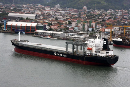
Bulk Carrier Petersfield
Douglas Channel, British Columbia
The Transportation Safety Board of Canada (TSB) investigated this occurrence for the purpose of advancing transportation safety. It is not the function of the Board to assign fault or determine civil or criminal liability. This report is not created for use in the context of legal, disciplinary or other proceedings. See Ownership and use of content.
-
Table of contents
Summary
On 25 September 2009, at 2246 Pacific Daylight Time, the open hatch bulk carrier Petersfield experienced a malfunction of its gyro heading feed and struck the west shore of Douglas Channel, B.C. The vessel sustained extensive damage to its bulbous bow, forepeak and collision bulkhead. There were no injuries or pollution and the vessel returned to Kitimat, B.C. under its own power.
Factual information
Particulars of the Vessel(s)
| Name of vessel | Petersfield |
|---|---|
| IMO Number | 8309713 |
| Port of registry | Nassau |
| Flag | Bahamas |
| Type | Open hatch bulk carrier |
| Gross tonnage | 27 818 |
| LengthFootnote 1 | 187.5 m |
| Draught | Forward: 6.75 m Aft: 7.60 m |
| Built | 1985 |
| Propulsion | 5973 kW B&W diesel engine driving a single fixed-pitch propeller |
| Cargo | Liner board and sackraft in rolls (15 404 tonnes) |
| Crew | 26 |
| Registered owner | Gearbulk Shipowning, Ltd. |
| Manager | Kristian Gerhard Jebsen Skipsrederei, A.S. |
Description of the vessel
The Petersfield is an open hatch bulk carrier with the bridge, accommodation and engine room aft of the 7 cargo holds. The vessel is fitted with 2 gantry cranes. A bulbous bow encloses the forepeak water ballast tank. A collision bulkhead segregates the forepeak from the port and starboard deep fuel oil tanks immediately aft.
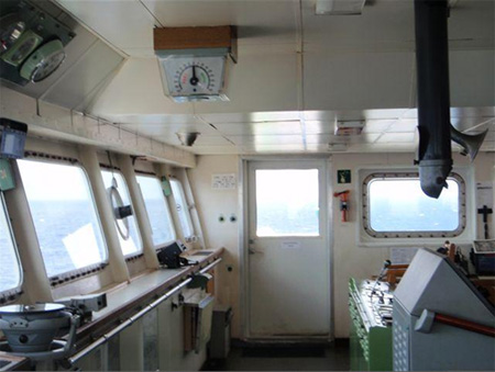
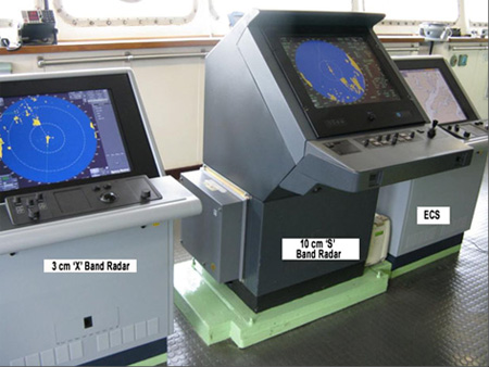
Situated next to each other on the port side of the bridge were 2 automatic radar plotting aid radars—a 3 cm radar and a 10 cm radar—and an electronic chart system (ECS) (see Figure 1).

Other navigation equipment included 2 gyro compasses,Footnote 2 3 global positioning systems (GPS), an automatic identification system (AIS), a course recorder, a simplified voyage data recorder (S-VDR), and an echo sounder. There were a total of 5 gyro compass repeaters: a digital repeater located forward near the centerline, an LED analogue repeater mounted above the window near the centerline, an analogue repeater on the port and starboard bridge wings, and an analogue repeater in the steering stand (helm). The magnetic compass and rudder angle indicators (one mounted on the deckhead and another mounted above the centerline window) could also be viewed from the steering stand.
History of the Voyage
The Petersfield departed Zhenjiang, China on 02 September 2009 bound for Kitimat, British Columbia. In the 96-hour pre-arrival report to Marine Communications and Traffic Services Centre (MCTS) Prince Rupert, the master reported periodic, unstable gyro headings on the 3 cm radar and ECS, as well as a malfunction with both the vessel's Sat Com B communication system and the fax machine. During the voyage, the heading markers had been reset each time they malfunctioned.
On 19 September, the vessel arrived in Kitimat and, on 23 September, a service technician boarded the vessel to diagnose the reported problem. The heading feeds to the ECS and 3 cm radar were rewired directly to the digital compass, and the system was subsequently tested and found to be in good working order.
On 25 September at 2006,Footnote 3 2 pilots boarded the vessel at which time the master/pilot exchange took place. One of the pilots set up his personal laptop computer, with navigational software loaded, near the port side bridge door and connected it to the ship's AIS unit. At approximately 2030, the vessel departed Kitimat for the 36-hour voyage to Crofton with 1 pilotFootnote 4 assuming conduct of the vessel. Accompanying him on the bridge were the master, the quartermaster,Footnote 5 and the third officer as the officer of the watch (OOW).
A passage plan had been developed by the ship's navigating team and the associated courses were entered into the ECS. The passage plan was not discussed during the master/pilot exchange, though the on-duty pilot viewed the plan at the chart table and recognized its similarities to his own intentions.
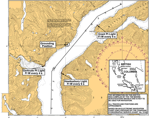
The initial portion of the voyage involved navigating through Douglas Channel, eventually passing Grant Point and later, Gertrude Point (see Appendix A). Following departure, the master was intermittently present on the bridge, going below from time to time to deal with administrative duties. The pilot used the 3 cm radar to monitor the vessel's progress, while the OOW used the 10 cm radar.Footnote 6 The quartermaster was positioned at the helm, steering the vessel using both the LED repeater and the repeater in the steering stand.
At 2048:48,Footnote 7 the 10 cm radar lost its heading input from the gyro compass and the OOW realigned it,Footnote 8 returning it to normal function. A similar event occurred again at 2054:18 and at 2058:33. Each time the heading was re-aligned.
Subsequently, starting at approximately 2100, there were 2 instances in rapid succession where the 10 cm radar again lost heading input, with the OOW re-aligning it both times. The pilot was then informed that the 10 cm radar was having a problem with the gyro heading, but he was not told about the earlier instances.
At 2129, MCTS Prince Rupert informed the vessel that Transport Canada (TC) required a second officer on the bridge due to the equipment malfunctions, including those of the 3 cm radar and ECS, that had been reported on the inbound voyage. Over the course of the ensuing communications, the pilot advised MCTS Prince Rupert that one of the radars was still having problems with the gyro heading. The master was called to the bridge and advised of the TC requirement. He then confirmed with the OOW that the 3 cm radar and ECS were functioning normally. This information was relayed via MCTS and subsequently, TC retracted its requirement for a second officer on the bridge.
At 2156:49 and again at 2208:18, the 10 cm radar lost its heading input from the gyro compass. In both instances, the OOW realigned the radar heading.
At 2216, the master, who had been below, returned to the bridge. Shortly afterwards, at 2228, with the vessel north of Grant Point and travelling at full sea speed,Footnote 9 the pilot ordered a course alteration from 242° Gyro (G) to 218° G, and verified the new heading by a visual check on the repeater.
At 2240:34, with the vessel still on a steady course, the image on the 10 cm radar screen began to rotate randomly and the visual compass alarm appeared. Moments later, the pilot stepped outside onto the port bridge wing in order to use his portable VHF to obtain weather information.Footnote 10 Meanwhile, the OOW informed the master of the jumping radar and following a brief discussion, the master left the bridge. At this moment the vessel's heading had started swinging to starboard unobserved and had changed from approximately 218° G to 231° G.
While the pilot was outside on the bridge wing, he noticed the bearing of a white flashing lightFootnote 11 on the port bow opening up, and considered that it could be Hawkesbury Light on the western tip of Hawkesbury Island. However, realizing that this light has limited sightlines to the north and has different characteristics, and also noticing a change in the wind, he stepped back into the wheelhouse at 2242:49.Footnote 12
Once back inside, the pilot glanced at the display of the second pilot's laptop, which was indicating that the vessel was off course. He then moved to the centerline and saw the heading on the digital gyro repeater swinging to starboard,Footnote 13 however, the analogue LED repeater unit was displaying a steady heading of 218° G. The gyro repeater in the steering stand was also displaying a heading of 218°. The pilot scanned the 3 cm and 10 cm radars, and ECS. The information available was contradictory.

The pilot then noticed a flashing white light abeam on the starboard sideFootnote 14 and he was also able to distinguish the tops of the mountains ahead of the vessel. He immediately ordered the OOW to call the master and requested that a searchlight be turned on. The pilot ordered hard-a-port at 2244:05. Once the vessel started swinging to port, both the LED repeater and the gyro repeater in the steering stand reflected the port swing. However, they were no longer properly aligned with the gyro compass.
Having been called by the OOW, the master returned to the bridge when at 2244:46 the pilot ordered full astern. The swing to starboard was arrested at 316° G, but the vessel could not avoid striking the shoreline at approximately 2245:25 in position 53°40.6′ N, 129° 08.8′ W (see Appendix A).
Crew assessment indicated bow damage with water ingress but no apparent signs of pollution. The master and pilot decided to return to Kitimat for a proper damage assessment. At 2313, the pilot notified MCTS Prince Rupert of the striking and of the plan to return to Kitimat. The pilot did not apprise MCTS of any damage but requested a tug to assist the vessel on its arrival at Kitimat.
At 0142 on 26 September, the vessel anchored at Kitimat.
Simplified Voyage Data Recorder Data Retrieval
The S-VDR on board the Petersfield recorded audio from various locations on the bridge as well as from the VHF radios. It also recorded the NMEAFootnote 15 strings from the digital gyro compass, GPS, echo sounder and speed log. Information contained in the NMEA strings included position, speed over ground, gyro heading, rate of turn and cross track distance. The S-VDR also recorded screen captures from the 10 cm radar at 15-second intervals. It does not record helm position or rudder angle.
Following the occurrence, information was downloaded from the S-VDR for the time period starting prior to the pilots boarding in Kitimat and concluding after the vessel returned.
Appendix B shows a chart of the occurrence area with the key events identified and giving the coinciding heading, course, and speed information. Appendix C is a graphical representation of the heading and rate of turn of the vessel during the occurrence time frame.
Vessel certification
The vessel was crewed and equipped in accordance with existing regulations and held a valid Safety Management System certificateFootnote 16 in accordance with the International Management Code for the Safe Operation of Ships and for Pollution Prevention (ISM Code).
Personnel certification and experience
The master, officers, and crew held certificates of competency appropriate for the type of vessel and the intended voyage.
The master had been with the same company for 21 years and had served 6 years as a master, the majority on board the Petersfield.
The officer of the watch had served for approximately 18 months on board various vessels since obtaining his second mate's certificate of competency in 2007. This was his second contract aboard the Petersfield. The duration of these contracts on board the Petersfield was 10 weeks on/10 weeks off.
The pilot held a Class I Pilot licence and had been with The British Columbia Coast Pilots Ltd. (BCCP) for 12 years.
Both the pilot and master had completed bridge resource management training. The OOW had not.
The quartermaster had sailed as a deckhand since 1990. This was his second time on board the Petersfield, having joined the vessel 8 months earlier.
Damage to the vessel
An underwater inspectionFootnote 17 revealed that the vessel was holed in the forepeak and that the bulbous bow was pushed in between frames 227 and 238, from the 8 m draft mark to a depth of 6 m below and predominantly on the starboard side.
Most of the floors, stringers, frames and brackets were found buckled, deformed or ruptured from frames 220–238 in the forepeak tank. Buckling of frames was also observed on the collision bulkhead. The maintenance room deck above the forepeak was deformed and ruptured at 3 locations.

Weather and Geography
The shores of Douglas Channel are steep, rising to high mountains a short distance inland. The steep cliffs direct the flow of winds, which are either in-flow or out-flow winds.
The nearest Environment Canada weather buoy was at Nanakwa Shoal, 15 nautical miles northeast of the occurrence location; this buoy indicated west-southwest winds of 10 knots, gusting to 12 knots around the approximate time of the occurrence. The weather experienced by the vessel was reported as southerly in-flow winds at 30 knots with clear visibility. The tide was ebbing resulting in a current between 0.3 and 0.7 knots.
Navigational Equipment Upgrades
In 2005, a new digital gyro compass and a synchro converter unit were installed aboard the Petersfield.Footnote 18 The original analogue gyro was kept on board, and a switch was installed to select between the two gyros. With the exception of the digital repeater at the bridge front, which was also replaced, all 4 older analogue repeaters (one on each bridge wing, the LED display, and the one on the steering stand) were retained.
In April 2009, the 3 cm radar and the ECS were replaced by new radar and ECS units. The synchro converter unit was set to provide a digital heading signal to this newly-installed equipment, however, it continued to provide an analogue heading feed to the older 10 cm radar and 4 of the 5 repeaters.
The manufacturer's specifications for the synchro converter unit installed on board notes the following with regard to checking the existing repeaters:
When replacing an old and worn out gyro it has sometimes been found too late that there are also old and worn out repeaters. Just one stuck repeater can ruin the whole system. … You should advise the owner that all repeaters should be mechanically checked, including the synchro brushes. The KW903 setting to work instructions offer advice, but the warranty we give does not include for faulty repeaters.
Heading Feed Malfunction
Prior to calling at Zhenjiang, the vessel had experienced repeated malfunctions of the heading marker, which moved erratically on both the 3 cm radar and the ECS, but not on the 10 cm radar. After each malfunction, the heading markers were manually reset. Despite several attempts, service technicians were unable to replicate and resolve the intermittent malfunction.
On 23 September in Kitimat, a service technician again boarded the vessel to address the malfunction with the heading markers. An NMEA heading feed from the digital gyro was fed through a splitter box directly to the ECS and to the 3 cm radar, thereby bypassing the synchro unit. The technician tested the gyro system with its repeaters and heading feeds to the navigation equipment. They were found to be in good working order.

Following the occurrence, the same technician re-boarded the vessel in Kitimat on 26 September and inspected the gyro system and the synchro converter unit. The technician checked the synchro line voltages and found them to be in order. However, a few loose connections were found in the synchro converter unit, the gyro distribution box, and the steering stand. The system was put into test mode and the repeaters stopped after 8 full rotationsFootnote 19 of the gyro compass, when the synchro converter unit became hot. After a cool-down period, the repeaters began working again. The fan inside the synchro converter unit was found to be faulty. The technician cleaned the fan, and recommended it be replaced should the problem persist. Further tests indicated that the gyro system, with its repeaters, was operating as required. The vessel then transited to Vancouver without reported problems with the heading feed.
On 14 October, service technicians from a different company boarded the vessel in Vancouver, B.C. The technicians traced connections, isolated equipment from the synchro converter unit and ran the self test function satisfactorily. After disconnecting its internal fan, the synchro converter unit was tested for 2 hours.Footnote 20 The analogue repeater headings were then compared and found to be out by approximately 20 degrees. After resetting the system, the repeaters swung wildly even though the status LED inside the synchro unit indicated that there were no problems. The system was switched off and on at which point it stabilized. The owner subsequently ordered the synchro converter unit be replaced.
Navigational Alarm Features
Prior to departing Kitimat, the ECS was loaded with the vessel's passage plan through Douglas Channel. The vessel's track was, at certain points, as little as 0.25 nm from the closest land. The default setting for the ECS Cross Track Error (XTE) alarm was increased from 0.05 nm to 0.19 nm and the XTE audible alarm feature was disabled. This was done because it was anticipated that the vessel's passage plan would not exactly coincide with the pilot's, which could have resulted in frequent alarms. The XTE alarm for the GPS was set at 0.25 nm. All audible alarm features on the 10 cm radar had been disabled.
Bridge Resource Management
Bridge Resource Management (BRM) is the effective management and utilization of all of the resources, human and technical, available to the bridge team to ensure the safe completion of the voyage. BRM includes passage planning, consideration of the size and composition of the bridge team, leadership, communications and interpersonal skills, situational awareness, problem solving, and decision making. In pilotage waters, the bridge team includes the pilot.
In this occurrence, once the pilots boarded the vessel, the master/pilot exchange took place and the Master-Pilot Exchange Card was completed. The exchange included the following points:
- the Sat Com B communication system and the fax machine remained defective;
- the erratic heading marker problems had been resolved;
- all other navigational equipment and machinery were functioning properly;
- all relevant charts were on board for the passage; and
- the vessel had produced a passage plan for the voyage.
There was no discussion of the pilot's passage plan or of the differences between it and the one the vessel had produced. There was no discussion about the status of the alarms on the various components of navigation equipment.
Pilotage and Passage Planning
On the west coast of Canada, responsibility for the operation, maintenance and administration of pilot services for compulsory pilotage areas lies with the Pacific Pilotage Authority (PPA), a crown corporation. The BCCP is a private company of licensed marine pilots that contracts its services to the Pacific Pilotage Authority.
Under the Pilotage Act, s. 25(2), "[a] licensed pilot who has the conduct of a ship is responsible to the master for the safe navigation of the ship."
Compulsory pilotage areas for Canada's West Coast, where local knowledge is considered essential for the safe and efficient navigation of vessels, are listed in the Pacific Pilotage Regulations. These areas encompass the entire coastal waters of British Columbia.
Traditional passage plans are defined by the courses to be followed. Deviations from the plan are made to accommodate external factors such as current, weather and traffic, and intrinsic factors such as vessel size and manoeuvrability.
The BCCP pilots rely on navigation corridors rather than track lines for passage planning. It is the BCCP's contention that routing vessels in B.C. coastal waters along navigation corridors, where each corridor offers a variety of possible routes, is a more prudent practice. The corridors allow a pilot to take due consideration of variables such as current, weather, traffic, vessel size and manoeuvring characteristics. This approach also avoids the concentration of traffic navigating along published tracks. Information on these corridors has not been published, and vessels have no access to a pilot's passage plan until the pilot is on board and briefs the bridge team. Each BCCP pilot develops his own passage plans based on his course book, observations and experience.
In this occurrence, the pilot used information for his passage plan based on his personal course book. This information was not entered into the ECS before commencing the voyage, nor was it communicated to the other members of the bridge team.
Analysis
Heading Feed Malfunction
Following the occurrence, a service technician in Kitimat tested the gyro system and observed that the synchro converter unit overheated and that the internal cooling fan was not functioning properly. Later, after the fan had been serviced, the vessel made its transit to Vancouver without any reported problems. In Vancouver, another service technician tested the system for overheating by disconnecting the internal fan and also observed problems with the unit. It should be noted, however, that the conditions of these tests imposed a load on the synchro converter unit that was more strenuous than normal service conditions. As such, the results of these tests, although suggestive of overheating, were not conclusive.
Nonetheless, during the occurrence voyage, there was a malfunction in the heading feed to the 10 cm radar that originated from the synchro converter unit. This malfunction coincided with the 'hanging up' of both the LED repeater and the steering stand repeater. There are 3 likely sources for this malfunction:
- Overheating due to an old repeater becoming stuck;
- An internal malfunction with the converter unit; or
- Loose connections within the synchro converter unit housing, gyro distribution box, or steering stand.
It is likely that the problems with the 10 cm radar and the repeaters were linked, however this could not be confirmed.
Events Leading to the Striking
A vessel will deviate from its heading under either internal or external influences. With respect to external influences, the tide and current in the channel at the time of the occurrence were negligible, and were not considered to be a factor. The centre of the vessel's windage area was aft and therefore the wind, which was reported as southerly in-flow at 30 knots, would have acted to oppose a course change to starboard. As such, this was also discounted as a factor in initiating the course alteration towards the western shore of Douglas Channel.
Internal influences such as a malfunction of the steering or rudder system, a rudder offset, or putting the rudder to starboard might cause a vessel to turn. The first 2 influences were discounted, however, since the vessel had responded to subsequent helm orders and there was no report of any rudder offset.
The application of starboard helm was examined through a detailed analysis of the S-VDR data. By plotting the vessel's heading and rate of turn against time (see Appendix C) it can be seen that, when the 10 cm radar started experiencing problems, the vessel's rate of turn was to port. In order for the quartermaster to maintain the vessel's desired heading, a small routine helm correction to starboard was necessary.
Since the vessel's analogue repeaters froze at the same moment, and since the quartermaster relied on these instruments as reference, there would have been no indication from the repeaters that further helm action was required. Thus, it is most likely that a small routine helm correction to starboard was made and subsequently maintained, resulting in the vessel continuing to turn to starboard.Footnote 21 It is uncertain why the quartermaster maintained the starboard helm, but there are 2 possibilities: either he did not observe the rudder angle indicator, or he observed it and disregarded it because there was no heading change.
Nevertheless, S-VDR data indicates that the starboard rate of turn continued until shortly after the pilot re-entered the bridge, as illustrated in Appendix C (between points C and D). It is likely that the quartermaster, having been alerted of a problem, initiated corrective action to port at that time. However, when the pilot ordered hard to port (75 seconds after entering the bridge) the vessel was just over 0.2 nm from shore. Travelling at 12 knots on a heading of 312° G, the vessel had progressed to a point where striking the shore could not be avoided. The vessel had commenced swinging to port when the starboard bow struck the shore at an angle of 30 to 45 degrees relative to the ship's heading, at approximately 10 knots.
Monitoring of Vessel's Progress
Navigation in confined waters such as Douglas Channel necessitates sailing in close proximity to shore where a constant monitoring of the vessel's progress is critical. This is especially true for a vessel transiting at full speed during hours of darkness when there are very few reference points ashore.
In this occurrence, monitoring of the vessel's progress was affected by several simultaneous events:
- The officer of the watch (OOW) was distracted by the 10 cm radar image rotating randomly and by his efforts to re-align the radar heading information with the gyro compass.
- The quartermaster's gyro repeaters malfunctioned and indicated to him that the ship was still on the ordered course of 218° G.
- The pilot stepped onto the bridge wing. Although this happened just after the gyro feed malfunction, there was no indication of a problem on the instruments he was monitoring, nor was he advised by the OOW of the latest problem with the 10 cm radar.
- After having been advised of the 10 cm radar problem, the master left the bridge.
As a result, the vessel's swing to starboard went unnoticed for a period of 2 minutes and 15 seconds until the pilot was alerted by visual cues from navigational aids onshore and a change in apparent wind. At this time, the vessel's rate of turn had increased to almost 40 degrees per minute to starboard, the heading had changed by over 50 degrees, the distance from shore had decreased to approximately 0.4 nm (see Appendix B) and the vessel was standing into danger.
Cross Track Error Alarms
The purpose of a cross track error alarm is to warn the bridge team when the vessel has deviated from its track by a preset amount. To do this, the system constantly monitors the vessel's position in relation to an intended track input by a user.
The default setting for the cross track error alarm on the Petersfield's electronic chart system (ECS) was 0.05 nm, but for this particular voyage had been increased to 0.19 nm. The default setting on the global positioning system (GPS) cross track error alarm was 0.25 nm.
At the time when the pilot re-entered the bridge and indicated that something was wrong, the vessel's cross track distance (with respect to the ship's passage plan) was 0.04 nm and the alarm would not have provided an earlier warning to the bridge team.
It is recognized that the ECS and GPS on the Petersfield were but 2 of the many instruments that could have provided the bridge team with useful information. However, the settings of both the GPS and the ECS cross track error alarms were such that, in this occurrence, the crew could not benefit from the alarm options available. They were therefore deprived of 2 potentially useful tools, which increased risk.
Bridge Resource Management
Performance has been defined as "a function of both the behaviour and accomplishment of a person or group of people. Performance includes the actions of a person or people and the result of the action or actions."
Footnote 22 Based on this definition, several observations can be made concerning the performance of the bridge resource management (BRM) on board the Petersfield, as described below.
Sharing of Information
While the 10 cm radar had heading feed problems on 7 different occasions in less than 75 minutes, this information was not effectively shared amongst the bridge team. Although the OOW informed the pilot of the problem on the fifth occasion, he did not indicate that it was frequently occurring. During radio communications with MCTS Prince Rupert, the problem was mentioned, but was not discussed among the pilot, the master and the OOW.
The master was not informed of the problem until the image on the 10 cm radar began to rotate randomly, which was the final instance of the malfunction before the striking. Furthermore, this occurrence of the radar malfunction was not shared with the pilot at this time.
A possible explanation for this lack of communication is that the master and the OOW did not consider the problem to be serious as they had been experiencing similar difficulties with the ECS and the 3 cm radar over a period of approximately 4 weeks prior to their arrival in Kitimat on 19 September. Nonetheless, as this information was not shared, opportunities to effectively manage or mitigate the problem at an earlier stage were missed.
Sharing of Passage Plans
The safety of any vessel in pilotage waters requires a common understanding among all bridge team members of the details of the voyage. This is especially important since masters and crews may be unaware of local conditions, while pilots are often unaware of a vessel's manoeuvring characteristics. A detailed, mutually agreed-upon passage plan (however defined) is therefore essential since it allows bridge team members to share navigational information, monitor the vessel's progress, identify deviations and raise navigational concerns. This is particularly advantageous in restricted waters.
In this occurrence, once the pilots boarded the vessel, key information was not shared with those best able to help ensure the vessel's safety. Although the Master-Pilot Exchange card was completed, the pilot did not share his intended passage plan, it was not entered into the ECS, and the rest of the team did not ask for further details. Consequently, the bridge team lacked a complete and common understanding of the vessel's intended route, potentially depriving them of the opportunity to effectively monitor the vessel's progress.
Navigation Equipment Modifications
For the many components on a ship's bridge to function fully, it is essential that they be inter-connected as one component requires information feeds from others, and in turn supplies information to other bridge components. For example, a radar uses input from a gyro compass, speed log and GPS, while in turn providing information to an ECS. It follows that the failure of one of these components can affect the proper functioning of other bridge equipment. This may be exacerbated when new components are added to the system or older components are replaced by new ones.
On the bridge of the Petersfield, the digital gyro compass fed a converted analogue signal, via the synchro converter unit, to the LED analogue repeater. This repeater, in turn, sent converted digital heading information to the automatic identification system (AIS) (see Figure 2). Following the modification of their input in Kitimat, the 3 cm radar and the ECS were fed directly from the digital gyro compass, bypassing the synchro converter unit. The result was that these components could no longer receive heading information from the analogue gyro if necessary, eliminating redundancy in the system.
In this occurrence, whatever caused the malfunction of the heading feed to the 10 cm radar also likely affected the functioning of the LED analogue repeater and the steering stand repeater used by the quartermaster. This contributed to the vessel deviating from its intended course. Furthermore, a situation was created where some components displayed inaccurate information while others remained accurate. This caused confusion, as the pilot was uncertain which components to trust, adding to the time necessary to determine the vessel's true position and heading.
As demonstrated by this occurrence, when new equipment is integrated with older installations, due consideration must be given to how the components are interconnected. Failure to do so has the potential to create undesired interdependence or a lack of redundancy, which increases the risk associated with a failure or malfunction in the system.
Findings
Findings as to causes and contributing factors
- Following departure from Kitimat, a system malfunction resulted in periodic and erratic heading information being delivered to the 10 cm radar and also led to the freezing of the analogue repeaters.
- At the same time as the repeaters froze, the quartermaster applied a small, routine amount of starboard rudder to make a minor course correction that resulted in the vessel commencing and continuing a starboard turn.
- Since the pilot had stepped onto the bridge wing and the OOW was distracted by the problem with the 10 cm radar, the vessel's progress was not effectively monitored and the starboard turn continued for over 2 minutes before the pilot became aware of the unintended deviation.
- Information about the repeated problems with the 10 cm radar was not effectively shared. Thus, an opportunity to effectively manage or mitigate the problem at an earlier stage was missed.
Findings as to risk
- The absence of a detailed, mutually agreed-upon passage plan deprives bridge team members of the means to effectively monitor a vessel's progress, compromising the principles of Bridge Resource Management.
- Failure to adequately consider the inter-dependencies of electronic components during the integration of new equipment with older installations may result in the creation of undesired reliance or of a lack of redundancy, which increases the risk associated with a failure or malfunction in the system.
Safety Action
Action taken
Following an internal investigation into the occurrence, the vessel's owner implemented several safety actions:
- 8 out of 11 similar synchro converter units in use by their fleet were replaced;
- A gyro-GPS compass alarm which is visible from the helm position will be installed on board 25 vessels per year over a 3 year period; and
- Various navigational procedures have been developed or updated regarding the setup of ECS/ECDIS alarms and passage planning.
This report concludes the Transportation Safety Board's investigation into this occurrence. Consequently, the Board authorized the release of this report on .
Appendices
Appendix A—Area of the Occurrence
Appendix B—Positions of Petersfield 10 minutes prior to striking
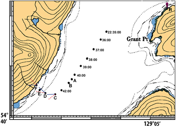
Note: Heading (solid line) and course over ground (dashed line) are indicated in last positions.
| Time (UTC) | Letter | Event | Gyro HeadingFootnote 23 | Course over Ground | Speed over Ground (knots) |
|---|---|---|---|---|---|
| 5:40:34 | A | first radar jumpFootnote 24 | 217.9 | 218 | 12.5 |
| 5:41:00 | B | pilot leaves wheelhouseFootnote 25 | 218.0 | 218 | 12.5 |
| 5:42:49 | C | pilot re-enters wheelhouse | 271.2 | 233 | 11.7 |
| 5:44:04 | D | hard to port | 311.3 | 280 | 10.6 |
| 5:44:46 | E | full astern | 302.9 | 306 | 10.6 |
| 5:45:25 | F | striking | 270.1 | 316 | 10.4 |
Appendix C—S-VDR Data
