
Rail transportation safety investigation report R19C0015
Uncontrolled movement of rolling stock and main-track train derailment
Canadian Pacific Railway Company
Freight train 301-349
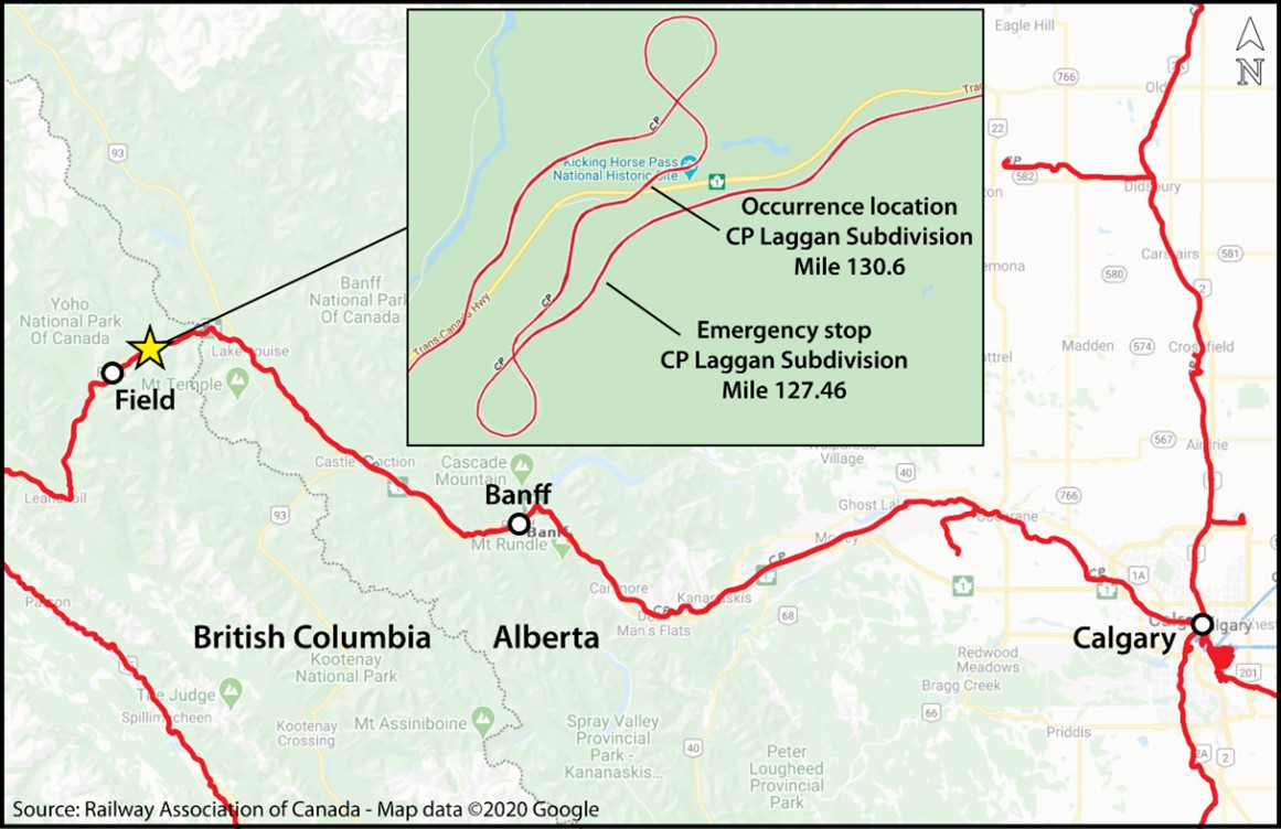
Mile 130.6, Laggan Subdivision
Yoho, British Columbia
The Transportation Safety Board of Canada (TSB) investigated this occurrence for the purpose of advancing transportation safety. It is not the function of the Board to assign fault or determine civil or criminal liability. This report is not created for use in the context of legal, disciplinary or other proceedings. See Ownership and use of content.
-
Table of contents
Executive summary
On 04 February 2019, the Canadian Pacific Railway Company (CP) freight train 301-349 being operated by a relief crew derailed on Field Hill near Field, British Columbia, on a 13.5-mile section of track with a steep descending grade (average 2.2%) and several sharp curves. The 3 crew members—a locomotive engineer, a conductor, and a conductor trainee—were fatally injured in the derailment.
The accident
Before the emergency stop
The unit grain train,Footnote 1 hauling 112 loaded hopper cars, weighing 15 042 tons, and measuring 6676 feet long, had left Calgary, Alberta, at about 1430Footnote 2 the previous day, operated by an inbound crewFootnote 3 consisting of a locomotive engineer and a conductor. It travelled west on the Laggan Subdivision, which runs from Calgary to Field. As the train progressed into the mountains, it encountered extreme cold temperatures (below −25 °C).
The train started its descent of Field Hill at approximately 2136. When the entire train was on the steepest part of the grade, it was not able to hold its speed at or below the maximum 15-mph limit. When the speed reached 21 mph, the inbound crew applied the brakes in emergency, as required by railway operating procedures. At approximately 2149, the train came to a stop at Partridge, British Columbia (Mile 127.46). From there, about 9 miles of descending 2.2% grade remained ahead of the train.
While stopped in emergency
After the inbound crew brought the train to an emergency stop, they had a job briefing with the trainmaster. It was decided to get the train underway again by releasing the emergency brake application and allowing the train’s air brakes to recharge as the train continued its descent (an operation called release and catch). In order to limit the train’s acceleration after the brakes were released, the pressure retaining valvesFootnote 4 had to be set to the high-pressure position on 84 of the rail cars. The conductor completed this task at approximately 2330.
Since the inbound crew was nearing the end of their shift, a relief crew was called in to complete the trip to Field. The relief crew started their shift at 2230 and reached the train—after a series of circumstances had delayed their arrival—at about 0020 on 04 February 2019, some 2.5 hours after the train had been stopped in emergency. Meanwhile, the ambient temperature had dropped to −28 °C, and the train’s air brake system had been leaking compressed air, reducing the brakes’ capacity to hold the train on the steep grade.
The uncontrolled movement
The relief crew took over care and control of the train and prepared to resume the trip, but waited in the locomotive cab for the track unit carrying the departing inbound crew to be clear of the main track before they began the release and catch.
At 0042, before the relief crew were able to start that process, the train began to creep forward, gradually accelerating uncontrolled down the steep grade. The train was able to proceed over back-to-back reverse curves as its speed reached 53 mph, but it was not able to negotiate the sharp 9.8° curve immediately before the Kicking Horse River bridge. Two locomotives and 99 cars derailed, beginning at Mile 130.6.
Safety deficiencies contributing to the accident
The investigation identified a number of safety deficiencies that contributed to the accident:
- The degradation of air brake systems in extreme cold temperatures
- The limitations of current train brake test methodologies to accurately evaluate air brake performance in these temperatures
- Training that was not specific to the unique operating conditions of the Laggan Subdivision, and the inadequacy of experience of employees supervising mountain-gradeFootnote 5 operations on this subdivision
- The need for better identification of hazards through reporting, data trend analysis, and risk assessments under CP’s safety management system to support risk mitigation measures
- The need for additional physical defences to prevent uncontrolled movement of rolling stock
Air brake system degradation in extreme cold temperatures
The leakage of compressed air from the train’s air brake system degraded the performance of the brakes in the extreme cold temperature. As a result, even though the inbound locomotive engineer had increased the amount of braking several times while going down Field Hill towards Partridge, the train’s speed continued to increase. When the speed reached 21 mph, the train crew applied the brakes in emergency.
After the train stopped, the air brakes continued to leak over the next 3 hours until they could no longer hold the train.
The investigation used several different methods to determine the effectiveness of the brakes at the time of the occurrence, most notably extensive testing of 13 cars recovered from the accident site; review of wheel temperature data for the cars on the train; brake retarding force calculations; and computerized train dynamics simulations.
The results all indicated that on the descent of Field Hill before the emergency stop the brake effectiveness of the train was in the 60% to 62% range. After the train had been stationary on Field Hill for approximately 3 hours, the brake effort had degraded to less than 40% of the theoretical maximum braking effort.
Several factors contributed to the degradation of the occurrence train’s braking performance, especially the leakage of compressed air from the air brake cylinders on the rail cars, which was aggravated by the extreme cold temperatures. If leakage is excessive, or interferes with the normal operation of air brake equipment, the brakes may not apply at all, may produce less than the expected amount of retarding force, or may release after a period of time.
Limitations of current train brake test methodologies
Most air brake issues can be detected when freight cars and locomotives are tested and inspected. The single car test is particularly relevant in this case: it verifies the intended operation of car brakes and ensures, among other things, that the brakes remain applied and do not exceed allowable leakage rates. Cars in service are required to undergo this test at least once every 5 years. The cars on the occurrence train met this requirement.
Because this test is usually conducted in the warmer environment of a maintenance shop, it is very difficult to diagnose issues that reveal themselves only in extreme cold temperatures. Also, it cannot be used to evaluate the operation of the brakes on an entire train.
One of the brake tests that an entire train undergoes is the No. 1 brake test, which is conducted by certified car inspectors when a train is assembled prior to departure. It verifies the brake pipe integrity and continuity, brake rigging condition, air brake application and release, and piston travel on each car in the train. The train cannot depart unless at least 95% of the train brakes are operative. The occurrence train passed a No. 1 brake test at Alyth Yard before departing Calgary at ambient temperatures of about −26 °C.
By confirming that brakes apply and release, the No. 1 brake test can verify the responsiveness of an air brake system, but it cannot determine its effectiveness. In addition, because this test is done on a stationary train, it does not necessarily expose brake system defects that may materialize only while the train is in motion.
Until train brake test methodologies accurately evaluate air brake effectiveness, trains operating in extreme cold temperatures may continue to have ineffective braking, increasing the risk of loss of control and derailment.
Sufficiency of training
The route through the Rocky Mountains on the Laggan Subdivision traverses some of the most challenging railway operating terrain in North America. Winter temperatures, ice, and snow compound these challenges—and present specific ones as well.
Locomotive engineers
Locomotive engineers have to be certified for the subdivision on which they operate trains. On the Laggan Subdivision, the certification requires about 3 extra months of training on Field Hill operations. This training includes trips to practise and achieve a qualification in descending the mountain grade and safely resuming operation of a train that is stopped on the grade.
At the time of the occurrence, CP’s Field Hill certification program did not have a module on the particular challenges of operating a train on mountain grade in extreme cold conditions. This kind of training could make locomotive engineers more aware of the issues associated with air brake system operations in extreme cold and increase their vigilance when they encounter situations similar to those that arose in this occurrence.
Conductors
At the time of the occurrence, CP required conductors to do a classroom review of relevant operating procedures using job aids and track schematics in order to work on Field Hill. New hires also attended a 2-week classroom exercise in a simulated environment, where they operated as conductors applying all rules and operating instructions. However, there were no simulated trips specifically for Field Hill, and conductors were not required to be Field Hill–certified. If the classroom training does not address the unique needs of the territory where the employees will be working, and if the employees do not obtain the relevant on-the-job training on that territory, they will not be adequately prepared to perform their duties safely.
Trainmasters
After the emergency stop on Field Hill, CP operating instructions and procedures required the inbound crew to hold a job briefing with the trainmaster to determine the best course of action and follow the trainmaster’s instructions.
Trainmasters overseeing train operations must have the technical expertise, knowledge, and experience to discuss options and provide solutions in complex operational situations, such as emergency brake recovery on a mountain grade.
In this occurrence, the trainmaster had qualified as a locomotive engineer through the management training program, but he had not qualified on the Laggan Subdivision and so had never received the Field Hill training. The trainmaster’s effectiveness as a technical leader was likely weakened by the mismatch between his experience and the requirements of supervising mountain-grade operations on the Laggan Subdivision.
Many railway companies in North America employ road foremen. This is also a supervisory role, but it focuses on the technical aspects of train operations (train handling, air brake operation, train dynamics, etc.). Road foremen are experienced locomotive engineers with considerable technical and operational expertise specific to the territory that they oversee. At the time of the occurrence, there was one road foreman at the Calgary terminal (the position had been vacant from 2016 to 2018), but his technical expertise and experience were similar to a trainmaster’s.
Need for better hazard identification, data analysis, and risk assessment
A safety management system (SMS) is an internationally recognized framework that allows companies to manage risk effectively and make operations safer. Risk assessments are a cornerstone of a fully functioning and effective SMS and are essential for a company to operate safely.
The Railway Safety Management System Regulations, 2015 require railway companies to conduct risk assessments, including when a safety concern is identified. To identify safety concerns, railway companies are required to continually analyze their operations, current or emerging trends, and any recurring situations. The analyses use information such as employees’ reports of safety hazards and data from safety monitoring technologies.
Safety hazard reports
Safety hazard reports involving poorly braking unit grain trains descending Field Hill in cold winter temperatures had been submitted by train crews in January and February for a number of years. As individual notifications of this hazard were closed, new, similar reports continued to be recorded through the reporting system. Although CP’s procedure for safety hazard reporting was actively followed at the Calgary terminal, the trend analysis it required was not being done. Consequently, year after year, the reports on the poor braking of unit grain trains on Field Hill were closed, no formal risk assessment was conducted, and insufficient corrective action was taken.
Data from wheel temperature detectors
CP collects data from the wheel temperature detectors on its network. The work done by CP to use detectors to identify cars with brake system issues was novel in the industry when it began in 2008. These detectors make it possible to identify cars with cold wheels—cold wheels being an indicator of poor braking performance. The data collected in winter allow the railway to monitor the temperature sensitivity and performance of car air brakes when they are most susceptible to leakage.
Wheel temperature detectors are a safety monitoring technology and, as such, data from them must be analyzed to identify safety concerns, trends or emerging trends, or recurring situations. However, at the time of the occurrence, CP did not analyze the data available for grain cars, and an opportunity was missed to identify the hazard and mitigate any risks related to the braking performance of grain trains in extreme cold temperatures.
Risk assessments before operational changes
Risk assessments must be conducted prior to implementing operational changes which have the potential to introduce new hazards or increase the level of severity of existing hazards. In the years preceding the occurrence, CP made incremental changes to the operating procedures for Field Hill, which included the speed threshold at which trains are permitted to descend Field Hill and the requirements for retainers and hand brakes after an emergency brake application. CP did not, however, do any risk analysis to assess how these changes would affect safety.
The need for additional physical defences against uncontrolled movements
This occurrence is one of 589 occurrences reported to the TSB from 2010 to 2019 that were related to unplanned and uncontrolled movements among all railways in Canada. Loss of control, as in this occurrence, was the causal category in 22 (4%) of them. While uncontrolled movements due to loss of control are low-frequency events, 59% of them (13 out of 22) affected the main track.
Uncontrolled movements pose a significant risk to railway employees. When such movements involve the main track, the public—including passengers and people in the vicinity of the railway tracks—can also be exposed to risk. The risks increase significantly when a train carries dangerous goods. Consequently, these are considered low-frequency, high-risk events.
The TSB remains concerned that the current defences are not sufficient to reduce the number of uncontrolled movements and improve safety. Unplanned/uncontrolled movements of railway equipment is on the TSB’s Watchlist 2020, which is a list of the key safety issues that need to be addressed to make Canada’s transportation system even safer.
New technologies are available
Many technological advancements are available to North American railways to enhance train brake performance, including automatic parking brakes, high-capacity fade-resistant brake shoes, control valves with a brake cylinder maintaining feature, and retention of dynamic brake force on remote locomotives. These technological enhancements are examples of physical defences that are likely to reduce the frequency of unplanned and uncontrolled movements of railway rolling stock. The major freight railways have been receptive to assessing these advancements, but have not fully implemented them. At the time of the occurrence, there were no regulatory requirements for their implementation.
Safety action following the accident
Transportation Safety Board of Canada
Soon after the accident, the TSB communicated critical safety informationFootnote 6 on
- the prevention of uncontrolled train movements for trains stopped in emergency on grades of less than 1.8% (TSB Rail Safety Advisory Letter 04/19, issued on 11 April 2019);
- air brake system inspection and maintenance on grain hopper cars used in CP unit train operation (TSB Rail Safety Advisory Letter 05/19, issued on 11 April 2019); and
- the effectiveness of the No. 1 brake test (TSB Rail Safety Advisory Letter 04/20, issued on 17 April 2020).
Transport Canada
For its part, Transport Canada introduced numerous initiatives, including a Ministerial Order requiring that trains stopped by an emergency brake application on a grade of 1.8% or greater immediately apply a sufficient number of hand brakes before recharging the air brake system. The Ministerial Order was later repealed when it was superseded by Rule 66 of the Canadian Rail Operating Rules.
Transport Canada also approved the use of automated train brake effectiveness technology in lieu of No. 1 brake tests on CP’s unit grain trains operating between points in Western Canada and the Port of Vancouver.
Canadian Pacific
For its part, CP
- revised the train handling procedures for the Laggan Subdivision with respect to the use of retainers and hand brakes before recovering from an emergency brake application on mountain grades;
- issued Operating Bulletin OPER-AB-015-19, which introduced both new cold-weather speed restrictions for Field Hill for trains with a weight per operative brake of 100 tons or greater and a requirement that undesired releases of brakes on Field Hill be reported immediately to the rail traffic controller;
- monitored wheel temperatures on all westbound grain trains passing by detectors installed on the Laggan and the Mountain subdivisions, which resulted in more than 5000 grain cars being removed from service for repair;
- developed an advanced training program for locomotive engineers to build their skills and readiness for dealing with adverse conditions in the field. Adverse conditions covered by the training program included response to minor and major changes in air flow and brake pipe fluctuation, response to an undesired release of the air brakes, and procedures for emergency air brake recovery.
TSB recommendations
To address the systemic safety issues that posed a significant risk in this occurrence, the Board made 3 recommendations, namely
- that the Department of Transport establish enhanced test standards and requirements for time-based maintenance of brake cylinders on freight cars operating on steep descending grades in cold ambient temperatures (TSB Recommendation R22-01);
- that the Department of Transport require Canadian freight railways to develop and implement a schedule for the installation of automatic parking brakes on freight cars, prioritizing the retrofit of cars used in bulk commodity unit trains in mountain grade territory (TSB Recommendation R22-02); and
- that the Department of Transport require Canadian Pacific Railway Company to demonstrate that its safety management system can effectively identify hazards arising from operations using all available information, including employee hazard reports and data trends; assess the associated risks; and implement mitigation measures and validate that they are effective (TSB Recommendation R22-03).
1.0 Factual information
1.1 The territory
On 03 February 2019, Canadian Pacific Railway Company (Canadian Pacific or CP) freight train 301-349 was travelling westward on the Laggan Subdivision, which runs from Calgary, Alberta (Mile 0.0) to Field, British Columbia (BC) (Mile 136.6).
The Laggan Subdivision is part of CP's main corridor to the west coast. It is one of several subdivisions through the Rocky and Cascade mountains characterized by steep grades and sharp curves. This route traverses some of the most challenging railway operating terrain in North America and is subject to environmental conditions that include extreme heat and cold, avalanches, rock slides, and slope destabilizations during spring runoff.
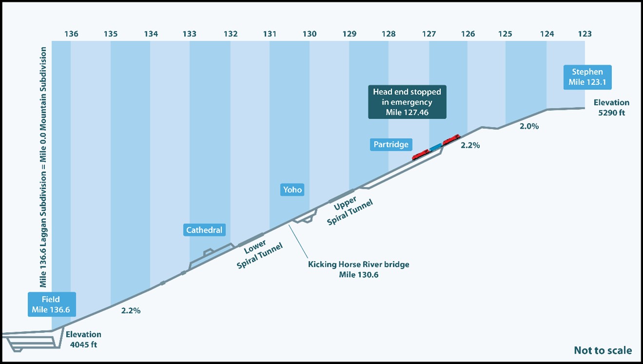
The route from Calgary to Stephen, BC (Mile 123.1), consists of a long gradual climb, followed by a steep descent at Field Hill.
The section of the Laggan Subdivision known as Field Hill runs 13.5 miles from Stephen to Field. It is designated as mountain gradeFootnote 7 and drops from an elevation of 5290 feet at Stephen to 4045 feet at Field. The descending grade varies between 1.7% and 2.2%.
The track through Field Hill goes through several tunnels and crosses the Kicking Horse River at Mile 130.6 between 2 spiral tunnels. The Upper Spiral Tunnel is 3255 feet long and extends from Mile 128.8 to Mile 129.5. The Lower Spiral Tunnel is 2922 feet long and extends from Mile 131.0 to Mile 131.5.
There are several sharp curves ranging from 8° to 10°, including back-to-back reverse curves. At Mile 130.2, the track has an 8.4° left-hand curve followed by a 7.9° right-hand curve; then, approaching the Kicking Horse River bridge, the curvature changes to a 9.8° left-hand curve.
In this occurrence, the train stopped in emergency at Partridge, BC (Mile 127.46). A few hours later, it started to roll on its own, uncontrolled. The head-end portion of the train derailed at Mile 130.6 (figures 1 and 2).
1.2 The accident
A summary of relevant events for this occurrence is provided in Table 1. A detailed timeline of the events that took place from the time the train stopped in emergency until it began to roll uncontrolled can be found in Table 2. Both of these tables are in section 1.2.4.
A description of locomotive and freight car brakes is provided in Appendix A. Information on inspection and testing of air brake systems is provided in Appendix B.
1.2.1 Before the emergency stop
On the morning before the occurrence, a CP train crew (the inbound crew)Footnote 8 was called at 1030Footnote 9 to report at Alyth Yard in Calgary for 1230. The crew was scheduled to operate freight train 301-349 westward on the Laggan Subdivision.
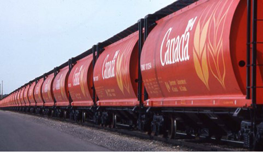
The train was a unit trainFootnote 10 hauling 112 loaded grain hopper cars. It weighed 15 042 tons and was 6676 feet long. It was powered by 3 distributed power (DP) locomotives—1 positioned at the head end, 1 in a mid-train position, and 1 on the tail end. The mid-train and tail-end locomotives were remote-controlled.Footnote 11
Earlier in the day at around 1210, the train had arrived at Alyth Yard with 1 car cut out (line 101, CP 603181).Footnote 12 Prior to departure from Alyth Yard, the train underwent a No. 1 brake test.Footnote 13 The test identified defective brakes on 1 more car (line 27, CP 607409), which was also cut out. With the 2 cars cut out, the train was cleared to leave, about 60 minutes later than expected. With the brake systems on 2 of the 112 cars cut out, the train had 98% of its car brakes operative with a weight of 131.1 tons per operative brake.
The train departed Alyth Yard at approximately 1430. It was operating in extreme cold temperature; when it passed Mile 65.6, a wayside hot box detectorFootnote 14 alerted the crew that the ambient temperature was −27 °C.
En route, the crew members experienced several delays in their progress westward with reduced speed due to low ambient temperatures, switch malfunctions, and train meets that added to their trip time. The locomotive engineer (LE) noticed increases in air flow whenever he applied the air brakes along the route,Footnote 15 but the air brake system performed as expected.
At approximately 2136, the train began proceeding down the steep grade that starts at Mile 125.6. The train could not maintain a speed below the maximum allowable limit of 15 mph; as the speed reached 21 mph, the crew applied the brakes in emergency and the train came to a stop at Partridge at around 2149. From the train’s stop location, about 9 miles of descending 2.2% grade still remained ahead of the train before the grade would decrease to between 0.5% and 0.4% for about 9000 feet starting at Field.
1.2.2 While stopped in emergency
At 2215, about 25 minutes after the train was stopped with an emergency brake application, the inbound crew and the trainmaster performed the required job briefing to assess the situation and determine the best course of action for recoveringFootnote 16 the emergency brake application. It was decided that the conductor would set the retaining valves (retainers)Footnote 17 to the high pressure (HP) position on 75% of the cars (84 cars), as required in the Field Hill operating procedures (FHOP), to facilitate a release and catch operation.Footnote 18 Because the inbound crew were close to the 10-hour limit of service in their collective agreement, the rail traffic control (RTC) director ordered a relief crew, who would take over control of the train and complete the trip to Field.
The members of the relief crew—an LE, a conductor, and a conductor trainee—were not immediately available; they were scheduled to come on duty at 2230. They had originally been ordered at Field to relieve another train and, at that time, the relief LE had opted to take a 2-hour advance callFootnote 19 (in accordance with his collective agreement) before coming on duty. Once en route, they travelled to Yoho by road vehicle, then were required to make the remainder of the trip to Partridge in a snow removal track unit.
At Yoho, the relief LE had a face-to-face job briefing with the trainmaster, who informed him of the decision to apply retainers on 84 of the train’s cars to assist in the safe recovery from the emergency brake application. Departing Yoho, the relief crew was further delayed as it was necessary to clear snow from a switch that led onto the main track.
While waiting for the relief crew to arrive, the inbound conductor set the required retainers on 84 (75%) of the cars, as decided. The task, which was made more difficult by the mountainous terrain, the extreme cold, and the darkness, took approximately 1 hour. The conductor returned to the locomotive at approximately 2330.
The relief crew arrived at Partridge at 0005 on 04 February 2019, and reached the train at 0020, approximately 2.5 hours after it had stopped in emergency.
1.2.3 The uncontrolled movement
Upon taking control of the train, the members of the relief crew had a job briefing with the inbound crew in the lead locomotive, and no concerns were raised. The relief crew then waited, as the train could not proceed down the hill until a track occupancy permit was cancelled,Footnote 20 which required the snow removal track unit transporting the inbound crew to be clear of the Yoho east switch. The LE stated in conversation with the RTC that he would not recover the emergency brake application until it had been confirmed to him that the track ahead was not occupied.
At 0042, while the relief crew was still waiting, the train started to roll on its own and the LE made an emergency radio broadcast. The engineering personnel on the main track overheard the transmissions and responded that they would indicate when they were in the clear at Yoho. The RTC repeated the emergency call a number of times to warn the engineering personnel on the main track to get clear of the track as soon as possible. The LE also asked the RTC to clear trains from the main track at Field, which was done, and to evacuate the Field bunkhouse.
When the train began its uncontrolled movement, the conductor and the conductor trainee left the locomotive cab with the intent to apply hand brakes to stop or slow the train; however, the train continued to accelerate and the LE told both crew members to return to the locomotive cab for their safety. They did not have an opportunity to apply any hand brakes. After the train was in motion, it accelerated rapidly and so it was not feasible to recover the emergency brake application.Footnote 21
Once the train entered the sharp curves on the descent, the LE broadcast that he expected the curve resistance to slow the acceleration of the uncontrolled movement and the train to “stall out” in the tunnel. The train was able to proceed over back-to-back reverse curves as its speed gradually accelerated to about 53 mph, well in excess of the maximum authorized speed; however, it was not able to negotiate the sharp 9.8° curve immediately before the Kicking Horse River bridge. The head end of the train derailed at Mile 130.6, at 0051. The 3 crew members were fatally injured.
1.2.4 Sequence of events
The sequence of events was established from a review of available information, including radio communication records, data from the locomotive event recorders (LERs), and interviews (Table 1).
| Date | Time | Event |
|---|---|---|
| 2019-02-03 | 1230:00 | The inbound crew is ordered to Alyth Yard for train 301-349. |
| 2019-02-03 | 1415:00 | The train completes a No. 1 brake test and an inspection at Alyth Yard. |
| 2019-02-03 | 1430:00 | The train departs Alyth Yard with 2 cars cut out: CP 603181 (line 101) and CP 607409 (line 27). |
| 2019-02-03 | 1436:00 | The crew members remind the RTC that they need to be off duty by their 10th hour, at 2230, in accordance with their collective agreement. |
| 2019-02-03 | 1506:00 | The LE observes an applied air flow event while bringing the train to a stop at Keith, Alberta, for a meet. |
| 2019-02-03 | 1510:00 | The train receives a roll-by inspection with nothing noted while coming to a stop at Keith to meet 3 trains. |
| 2019-02-03 | 1519:00 | The RTC informs the crew about a problem with the west switch at Keith. |
| 2019-02-03 | 1639:00 | The RTC contacts the crew and asks for a 10 psi brake application and release to address a warm wheel detected on the car in position number 107 (DME 51034). |
| 2019-02-03 | 1720:00 | The LE informs the RTC that the train’s speed is now restricted to a maximum of 25 mph through Canmore, Alberta, and Banff, Alberta, after the wayside detector at Mile 65.6 broadcasted a −27 °C cold temperature alert on the standby channel. |
| 2019-02-03 | 1805:00 | The LE observes an applied air flow event while bringing the train to a stop at Banff to meet a train. |
| 2019-02-03 | 1838:00 | The RTC informs the crew of impending delays at Eldon, Alberta, to meet other trains, and for weather and switch problems. |
| 2019-02-03 | 1909:00 | The LE observes an applied air flow event while bringing the train to a stop at Eldon to meet 2 trains. |
| 2019-02-03 | 1910:00 | The train receives a roll-by inspection with nothing noted while coming to a stop at Eldon for meets. |
| 2019-02-03 | 2014:00 | The train departs Eldon siding. The RTC relieves the crew of inspecting duties for their train at the end of their tour of duty at Field. |
| 2019-02-03 | 2125:00 | The LE starts to advance the throttle from notch 1 to the notch 2-3 position at a speed of 2 mph to keep the train moving on the approach to Stephen. |
| 2019-02-03 | 2128:13 | The LE makes an initial air brake application at Mile 123.12 while starting down the grade at Stephen. |
| 2019-02-03 | 2128:37 | The LE observes an applied air flow event. |
| 2019-02-03 | 2136:45 | While descending Field Hill, the LE makes the first of several incremental brake pipe pressure reductions as the train speed continues to increase. |
| 2019-02-03 | 2137:15 | The LE observes an applied air flow event after he makes the first incremental brake pipe pressure reduction. |
| 2019-02-03 | 2148:08 | The LE and the conductor apply the train brakes in emergency as the speed reaches 21 mph. |
| 2019-02-03 | 21:48:25 | The LE makes an emergency broadcast on the radio. |
| 2019-02-03 | 2149:33 | The train comes to a stop with the head end located at Mile 127.46. |
| 2019-02-03 | 2153:00 | The RTC asks the crew if the air is coming back, after the brakes were applied in emergency. The crew responds that they need to hold a job briefing with the trainmaster to determine what to do next. |
| 2019-02-03 | 2215:00 | The trainmaster and the crew conduct a job briefing over the radio. During the discussion, the LE mentions the applied air flow events that he observed along the way. A decision is made to set retainers on 75% of the cars (84 cars) per the Field Hill operating procedures. |
| 2019-02-03 | 2230:00 | The trainmaster arrives at Yoho by road vehicle. The RTC director informs the trainmaster that the relief crew will be on their way to Yoho shortly by road vehicle. The track foreman starts preparing a snow removal track unit to transport the relief crew by rail from Yoho to the train. The conductor exits the cab of the locomotive and begins setting the retainers. |
| 2019-02-03 | 2245:00* | The relief crew arrives at Yoho by road vehicle. |
| 2019-02-03 | 2315:00 | The track foreman, to prepare the way for the snow removal track unit, attempts to line the switch from the storage track onto the main track, but the switch is fouled with frozen snow. |
| 2019-02-03 | 2330:00 | The conductor returns to the locomotive cab after setting 84 retainers. |
| 2019-02-03 | 2335:00 | While waiting in Yoho, the relief LE holds an in-person briefing with the trainmaster. The decision to use retainers on 75% of the cars is discussed, and the relief LE does not object. While the relief LE is with the trainmaster, they also have a briefing via radio with the inbound LE. |
| 2019-02-04 | 0015:00 | The snow removal track unit departs Yoho and travels on the main track to transport the relief crew to the train. |
| 2019-02-04 | 0031:00 | The relief crew reports to the RTC that they are now on board the train. |
| 2019-02-04 | 0042:02 | The train starts to roll on its own with the emergency brake application still engaged. |
| 2019-02-04 | 0042:36 | The conductor and the conductor trainee get off the train to apply hand brakes. |
| 2019-02-04 | 0042:38* | The LE broadcasts over the radio that the train is in emergency and travelling at 1 mph. |
| 2019-02-04 | 0042:40* | The LE tells the conductor and the conductor trainee to return to the cab. |
| 2019-02-04 | 0048:30 | The train, now travelling at 22 mph, passes the Partridge west signal, which is displaying a stop indication protecting the block ahead with a track occupancy permit still in effect between Partridge and Yoho. |
| 2019-02-04 | 0048:30 | The inbound crew aboard the snow removal track unit moves clear of the Yoho east switch. |
| 2019-02-04 | 0048:32 | The Yoho east switch is manually lined in the normal position, and the track foreman reports this to the RTC. |
| 2019-02-04 | 0049:00 | The train passes the Yoho east switch. |
| 2019-02-04 | 0049:10 | The LE broadcasts that the train is entering Upper Spiral Tunnel and that its speed is 40 mph. |
| 2019-02-04 | 0050:05 | The LE broadcasts that the speed of the train is 48 mph. |
| 2019-02-04 | 0050:20 | The LE broadcasts that the speed of the train is 51 mph. |
| 2019-02-04 | 0050:27 | The tail end portion of the train separates between positions 85 and 86. |
| 2019-02-04 | 0050:31 | The midsection of the train separates between positions 36 and 37. |
| 2019-02-04 | 0050:34 | The tail-end remote locomotive comes to a stop just inside the west portal of the Upper Spiral Tunnel. |
| 2019-02-04 | 0050:54* | The head end of the train derails in the Kicking Horse River. |
| 2019-02-04 | 0051:20 | The wayside detector broadcasts an alert after the train passes Mile 130.2 that the power is off and not working, and also provides a car count with fewer cars than are actually on the train. |
* Estimated time based on the surviving LER data obtained from the DP mid-train and rear locomotives.
After the train had stopped in emergency on the mountain grade at Mile 127.46, approximately 2.5 hours elapsed before the relief crew was on board and preparing to recover the emergency brake application. Table 2 describes the activities that took place and the delays incurred during the 3 hours that the train remained stationary on Field Hill.
| Date | Time | Elapsed time | Events |
|---|---|---|---|
| 2019-02-03 | 2150 | 00:00:00 |
|
| 2019-02-03 | 2153 | 00:03:00 |
|
| 2019-02-03 | 2215 | 00:25:00 |
|
| 2019-02-03 | 2230 | 00:40:00 |
|
| 2019-02-03 | 2245 | 00:55:00 |
|
| 2019-02-03 | 2253 | 01:03:00 |
|
| 2019-02-03 | 2315 | 01:15:00 |
|
| 2019-02-03 | 2327 | 01:37:00 |
|
| 2019-02-04 | 0015 | 02:25:00 |
|
| 2019-02-04 | 0020 | 02:30:00 |
|
| 2019-02-04 | 0031 | 02:41:00 |
|
| 2019-02-04 | 0042 | 02:52:00 |
|
1.3 Site examination
The derailment site spanned 1.2 miles, from Mile 129.4 to Mile 130.6. It was located about 6.8 track miles northeast of the town of Field.
The train had separated into 3 sections during the derailment (Figure 3).

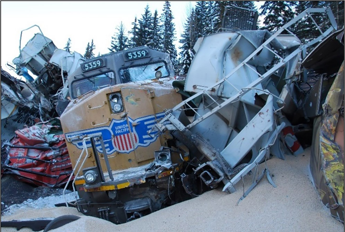
The front portion of the train, including the lead locomotive (CP 9538) and the first 35 cars, had derailed on the curve immediately before the Kicking Horse River bridge at Mile 130.6 (Figure 4).
The head-end locomotive, CP 9538, was lying on its left side in the riverbed, some 35 feet below the track level. The river was quite shallow, and the surface was frozen and covered with snow. A patch of open water about 20 feet in diameter was visible underneath and adjacent to the locomotive, where the ice had broken when the locomotive fell onto the riverbed. An inspection of the underside of the locomotive showed little indication of ground contact, but the rest of the locomotive had sustained extensive damage.
Several derailed cars were lying on the river embankment, and the remaining cars in this section of the occurrence site had derailed along the right-of-way. The head-end cars had been scattered on the embankment or had come to rest in the treed area some distance away from the track.
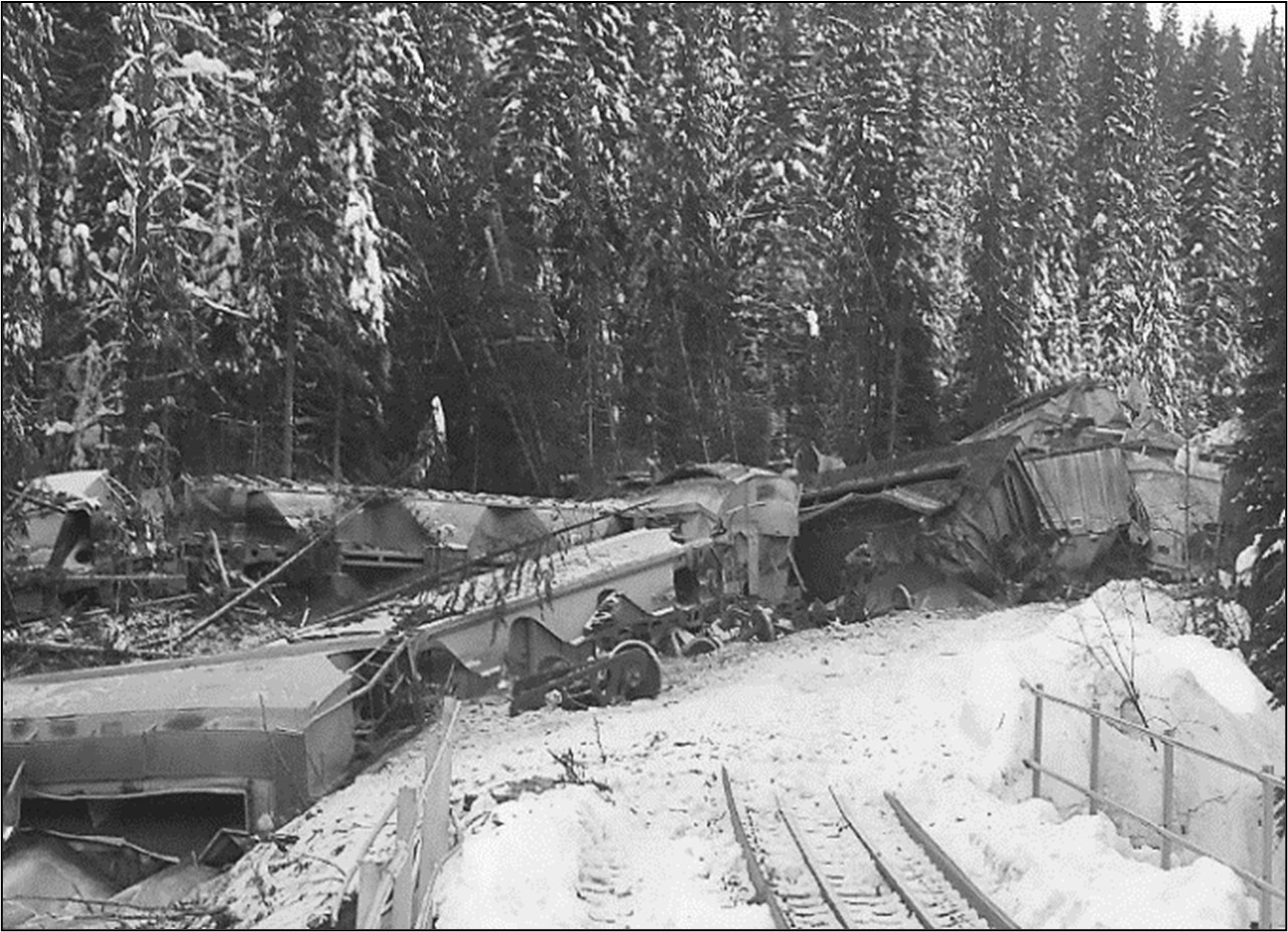
Further back in the train, at around Mile 130.2, 40 cars from the middle portion of the train had derailed on their side and in a pile-up. Several of these cars were underneath a multi-lane overpass structure where Highway 1 passes above the track. Some cars were leaning against the bridge piers, which sustained superficial damage (Figure 5).
The mid-train remote locomotive, UP 5359, had derailed but stood upright among other cars stacked in a side-by-side pile-up (Figure 6).

Eight cars on the trailing end of the middle portion did not derail and were not damaged.
In the rear portion, rolling stock was located both inside and outside the Upper Spiral Tunnel. Outside the tunnel, 7 cars were derailed on their side and 15 cars were derailed in a pile-up on the mountainside. Inside the tunnel, 4 cars had stayed on the rails, 1 car had the rear truck derailed, and 2 cars were upright with all trucks derailed. The tail-end remote locomotive, CEFX 1040, remained on the track some 475 feet inside the tunnel (Figure 7).

The track examination did not show any breaks or gaps in the rail, or any indication of lateral shift. The rail was still solidly anchored to the hardwood crossties. The track structure was solidly frozen in the ground. There was no indication that the high rail (outer side of the curve) had canted outward or rolled over.
1.3.1 Inspection of rolling stock
Access to the rolling stock was limited in many areas due to the wreckage, spilled car contents, and confined workspace. In many cases, key components of interest were damaged beyond the point at which meaningful information could be obtained. The inspection focused on the visible portions of the rolling stock, in particular the brake system, the wheelsets, and the position of the various valve handles on the cars. All of these could provide insight into the operation of the train at the time of the occurrence.
The car air brake system appeared to be properly set up. The retainer handles that were visible appeared to be in the HP position. The examination of the hand brakes did not provide any indication that they had been applied. The brake rigging and wheel tread surfaces were all relatively clean and with no evidence of snow or ice buildup.
The head-end locomotive was extensively damaged; a section of the control stand with various control levers was removed for visual inspection off site. This inspection indicated that the controls were operational and had not malfunctioned in any way before the locomotive derailed. The electrical wiring was intact, as were the controller mechanical linkages.
The following components were set aside for further examination and testing:
- the 12 grain cars that had not derailed, plus the grain car that remained upright with 1 truck derailed;
- the tail-end locomotive;
- the brake shoes on all 3 locomotives (Figure 8); and
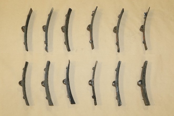
- the car wheelsets that could be recovered, about 78% of the total wheels (Figure 9).

1.4 Weather
At the time of the occurrence, the sky was clear with light gusting winds. Although it had recently snowed in the area, the snow was not covering the top of the rail head. The ambient temperature was determined to be about −25 °C when the train stopped in emergency. By the time the train started to roll on its own around 0042, the temperature had decreased to −28 °C.
1.5 Subdivision information
The Laggan Subdivision is part of CP's main corridor to the west coast. The subdivision extends from Calgary (Mile 0.0) to Field (Mile 136.6), and consists primarily of a single main track, with a double-track portion located between Lake Louise, Alberta (Mile 116.2), and Stephen (Mile 123.1). At Field, the track connects with Mile 0.0 of the Mountain Subdivision.
Train movements are governed by the centralized traffic control (CTC) system, as authorized by the Canadian Rail Operating Rules (CROR), and dispatched by an RTC located in Calgary. Calgary is also the home terminal for train crews, trainmasters and road foremen operating on the Laggan Subdivision.
Laggan Subdivision freight traffic volumes for 2015–2019 are shown in Table 3.
| Year | Volume (million gross ton-miles per mile) |
|---|---|
| 2015 | 62.8 |
| 2016 | 65.3 |
| 2017 | 65.9 |
| 2018 | 70.6 |
| 2019 | 70.1 |
1.6 Track information
In the vicinity of the derailment, the main track consisted of 136-pound continuous welded rail manufactured in 2000. On the open track, the rail was laid on 14-inch double-shouldered tie plates and was fastened to hardwood ties with 3 spikes per tie plate. Inside the spiral tunnels, the rail was secured to steel ties using spring clips. The ballast was clean crushed rock. The shoulders were about 12 inches wide, the cribs were full, and the drainage was good.
The track is normally inspected a minimum of twice per week as required by CP’s Red Book of Track & Structures Requirements. The last regulatory track inspection, conducted as required by the Transport Canada (TC)–approved Rules Respecting Track Safety, was conducted on 31 January 2019. There were no deficiencies noted during the inspection near the derailment location.
From Mile 122.9 to Mile 136.6, the maximum authorized speed on this track is 20 mph. Freight trains having a weight per operative brake of 100 tons or more are restricted to a maximum authorized speed of 15 mph.
1.7 Personnel information
1.7.1 Inbound crew
The inbound crew was composed of an LE and a conductor. Both crew members met established rest and fitness requirements and were qualified for their respective positions.
The LE was hired as a conductor trainee in November 2005. He qualified as a conductor in May 2006. He spent 5 years on yard assignments and then moved to road service. He entered the LE training program in January 2012 and qualified in August 2012. After qualification, he returned to his previous position as a conductor and worked as a relieving LE on various subdivisions when an assignment was available. In 2018, he moved permanently to the LE spare board for the Laggan Subdivision. He had followed the program specifically designed for Field Hill operations and was Field Hill–certified.Footnote 22
The conductor started training as a conductor in April 2018 and qualified at the end of August 2018. After qualifying, she worked on yard assignments in Alyth Yard and in the Carseland Cargill facility and on road switching assignments. The occurrence trip was her 4th trip working as a conductor on the Laggan Subdivision.
1.7.2 Relief crew
The relief crew consisted of an LE, a conductor, and a conductor in training (the conductor trainee). The relief LE qualified in 1996, resigned in 2002, and was rehired as a conductor/LE in 2003. This was his 1268th trip on the Laggan Subdivision. The relief conductor qualified in 2007 and was on his 171st trip on the Laggan Subdivision. The conductor trainee was hired in 2018 and was taking his 13th training trip on the Laggan Subdivision.
The relief crew members had arrived at Field in a westbound train on the morning of 03 February 2019. They went off duty at 1120 and had more than 8 continuous hours off-duty time, in accordance with established rest and fitness requirements. However, from the early morning hours of 03 February 2019 until 2200, a power outage affected heating and electrical power at the CP’s bunkhouse in Field, where the relief crew was resting. The power outage also resulted in a loss of communications, meaning that crews had to be notified by supervisors, in person, when called to duty. In addition, the generator in Field ran out of fuel, and the occupants of the bunkhouse resorted to using the propane-fuelled cooking stove as a heat source. The temperature inside the bunkhouse facility had reportedly dropped to as low as 8 °C before power was restored.
1.7.3 Trainmaster
The trainmaster joined CP in 2008 as an RTC where he gained preliminary experience dispatching the Laggan Subdivision during his first year of service. He qualified as a conductor in 2013 and as an LE in 2015 under management training programs,Footnote 23 and became a trainmaster in January 2016. At the time of the occurrence, he had taken over 100 trips as an LE, most of them on mountainous territory on the Cranbrook and Windermere subdivisions, and had worked on the Laggan Subdivision as a conductor. The trainmaster was not a Field Hill–certified LE, nor was it a CP requirement for supervisors on that territory.
1.8 Canadian Pacific’s grain car fleet
The 112 grain cars on the train were assembled from 3 separate fleets of hopper cars: a fleet owned by the Government of Canada, CP’s own fleet, and a fleet of leased cars.
1.8.1 Government of Canada fleet
From 1972 to 1994, the Government of Canada purchased some 13 500 covered hopper cars to carry Western Canadian grain for export (Figure 10). Many of these cars have been removed from service by attrition, but, at the time of the occurrence, more than half of them were still in service and represented approximately one third of the cars in active grain service in Canada. At the end of December 2018, the Government of Canada’s grain hopper car fleet consisted of 7749 cars, almost evenly distributed between CP and Canadian National Railway Company (CN). In 2007, the Government of Canada signed an agreement with CN and CP for the operation, maintenance, and refurbishment of the federal fleet of hopper cars.Footnote 24
CP is required by agreement to maintain capacity for the transportation of grain by refurbishing the Government of Canada fleet of hopper cars, upgrading cars to carry higher loads, and replacing some of the retired cars with new higher-capacity hopper cars. Like any other commodity freight car, the grain hopper cars require repairs. TC monitors the number of bad-order cars to ensure that efficient and timely maintenance is done, consistent with the Association of American Railroads (AAR) Field Manual of the AAR Interchange Rules.
The cars in CP’s fleet that are owned by the Government of Canada are designated as CP 600000–608591 series. They were mainly built between 1972 and 1985, and are equipped with Wabcopac or Nycopac truck-mounted brakes; they are not equipped with slack adjustersFootnote 25 to compensate for wheel and brake shoe wear and to maintain uniform piston travel.
1.8.2 Canadian Pacific hopper cars
Some of the hopper cars on the train were from CP’s own fleet: CP 384000 series cars and SOO series cars. The CP 384000 series cars were built in 1981 and were equipped with Wabcopac truck-mounted brakes, but were not equipped with slack adjusters. The SOO series cars were built between 1994 and 2006 and were equipped with newer technology, namely truck-mounted or body-mounted brakes that have automatic slack adjusters.
1.8.3 Leased cars
The leased cars in CP’s grain fleet came from various car owners in the United States and were mainly equipped with body-mounted brake rigging systems with automatic slack adjusters.
1.8.4 Fleet composition of the occurrence train
The fleet composition of the occurrence train was as follows:
- 40 cars: 2 cars in the CP 384000-384999 series and 38 Government of Canada cars in the CP 600000–608591 series;
- 51 cars designated as SOO series, from CP’s own fleet; and
- 21 cars from the fleet of leased cars.
The air brake configuration for the cars on the train is provided in Appendix C, with the replacement history of the brake components. The maintenance history indicated that the cars on the occurrence train were maintained according to regulatory standards.
1.8.5 Renewal of Canadian Pacific’s grain car fleet
Changes to the Canada Transportation Act in May 2018 allowed adjustments to reflect the costs incurred by railway companies to obtain and maintain hopper cars for the movement of grain. In response, CP initiated a review of its existing grain fleet and developed a multi-year plan to replace part of the fleet with new and higher capacity cars. CP started taking delivery of the new grain cars in September 2018. Since then, CP has been receiving new grain cars monthly. The program is expected to be complete by December 2022. As of October 2021, CP has brought into service a total of 5355 new grain cars (4500 purchased and 855 leased).
1.9 Railway operations in winter
Winter conditions in northern climates, such as cold temperatures, ice and snow, present specific challenges for railway operations.
In recognition of these seasonal challenges, most railways operating in the northern United States and Canada establish an annual winter operating plan that presents strategies to remain operationally viable and safe during the winter months. Typical winter operating plans may include proactive actions, for example:
- pre-seasonal servicing of switch heaters and snow fighting equipment,
- servicing of locomotive cooling systems and locomotive “hot start” systems,
- ensuring a supply of suitable replacement rail in anticipation of cold-related rail breaks,
- limiting train length to combat difficulties associated with train air supply on long trains,
- renewing all end-of-car hose gaskets on intermodal and grain cars,
- qualifying trains’ air brake systems to half of the allowable regulatory leakage rates,
- speed reductions,
- 30-minute standing air brake leakage test,
- restricting loaded unit train operation during the night when extreme temperatures are forecasted, and
- reinforcing the importance of appropriate clothing and personal protective equipment for employees working outdoors.
1.9.1 Additional challenges in extreme cold temperatures
Beyond the usual challenges faced in winter, extreme cold temperatures (about −25 °C)Footnote 26 add another level of complexity to railway operations. For example, rails can become brittle and snap under load, and pull-aparts can occur when the rail anchors cannot overcome the intense compressive forces created when cold rail contracts.
It is well known in the North American railway industry that cold temperatures can result in air leakage from freight car air brake systems. Footnote 27 Rubber seals and gaskets become stiff and metal contracts, resulting in leakage of compressed air. In extreme cold temperatures, the effectiveness of air brake systems can further decline. Equally of concern is that symptoms associated with degraded braking efficiency on a train may not be obvious or straightforward for an LE to properly diagnose.
To compensate for air leakage, air brake systems provide brake pipe pressure maintainingFootnote 28 to replenish the lost compressed air. However, brake cylinders are only pressure maintained to approximately 8 to 12 psi, regardless of the air brake application in effect.
Brake system leakage in extreme cold temperatures can be particularly problematic in mountain grade territories, where safe train speed control on long descending grades requires higher levels of brake cylinder pressure (BCP) for an extended length of time.
1.9.2 Previous winter restrictions for westbound trains operating on Field Hill
In 2014 and 2015, CP implemented a number of procedural modifications to mitigate some of the challenges of operating trains on Field Hill in extreme cold temperatures.
In 2014, and after an extended period of extreme cold temperatures, CP decided to temporarily limit the speed of grain trains to 10 mph when the temperature reached −20 °C, and to stage grain trains (hold them in a queue) during the night when the temperature dropped below −25 °C. Staging the trains allowed them to descend Field Hill in the warmer daylight hours, which assisted in better braking.
This decision came after several grain trains had difficulties controlling their speed on Field Hill during extreme cold temperatures. Subsequent inspections of 2 of these trains (made up of CP 600000–608591 series cars) in Golden, BC, and in Eldon, Alberta, revealed leaking brake cylinders. Railway certified car inspectors noted that, in Golden, the brake cylinders had leaked off on a number of cars within 15 minutes and that, in Eldon, brake cylinders had leaked off within 20 minutes. These same trains did not have abnormally high leakage when they received their pre-departure inspections and No. 1 brake tests at Alyth Yard. However, leakage intensified with the colder temperatures encountered in the mountains.Footnote 29
On 12 November 2015, ahead of the winter season, CP issued General Bulletin Order (GBO) M599 for westbound trains on the Laggan Subdivision. The bulletin restricted train speed to a maximum of 10 mph from east siding switch at Partridge to Field when the temperature reading at Mile 111.0 dropped below −25 °C, until braking was seen to be sufficient. The GBO was cancelled on 14 March 2016 concurrent with the end of the winter operating season.
At the time of the occurrence, CP had a system-wide winter contingency plan, however, this plan provided no additional seasonal restrictions specific to mountain grade train operations.
1.10 Field Hill operating procedures
Operating instructions can be found in CP time tables, General Operating Instructions (GOIs), GBOs, Special Instructions (SIs), operating bulletins, and train handling procedures. In this investigation report, the instructions applicable to Field Hill are called the Field Hill operating procedures (FHOP).
The investigation reviewed several years of FHOP dating back to 1985.
In 1990, the time table for the Laggan Subdivision contained SIs for trains left standing on grades:
SPECIAL INSTRUCTIONS
(HEAVY HAUL SYSTEMS)1. TRAINS LEFT STANDING ON GRADE
When the unit controlling a train is equipped with pressure maintaining, the train brakes may be left applied to hold the train when standing on a grade until ready to proceed, provided the train is not left unattended. If stop exceeds two hours and it is considered necessary to recharge the brake system before proceeding, sufficient hand brakes must be set to hold the train while recharging. Hand brakes must be set on rear of the train when on an ascending grade and on head end of the train when on a descending grade. Before releasing hand brakes, a sufficient brake pipe reduction must be made to hold the train while hand brakes are being released.Footnote 30
According to these instructions, if a heavy train was stopped on Field Hill in excess of 2 hours and it was considered necessary to recharge the brake system, a sufficient number of hand brakes were to be applied to hold the train stationary while recharging.
The SIs were migrated from the Laggan Subdivision time table into the operating bulletins issued in conjunction with the time table. The first operating bulletin that contained the SIs was Heavy Haul – Canada Operating Bulletin No 93-A issued on 18 April 1993. The SI last appeared in Operating Bulletin No 93-C issued on 01 November 1993.
In 1997, after an accident on Field Hill that resulted in the derailment of 66 cars during an uncontrolled high-speed descent,Footnote 31 CP dedicated operating officers to accompany crews on every train operating westward on Field Hill for a period of 11 days to monitor operating practices and compliance with operating instructions. CP also issued Operating Bulletin 188 on 05 December 1997, which addressed emergency brake recovery procedures on Field Hill.
After an incident on 02 January 1998, in which a freight train handling 112 cars ran uncontrolled between the Upper Spiral Tunnel and Field,Footnote 32 CP assigned 7 operating officers and 8 experienced LEs to ride all trains for a 3-month period between Lake Louise and Field. They were tasked with monitoring train crew performance, revising speed restrictions on Field Hill, and devising the proper method of using the train braking systems on the steep grade. CP then issued 2 bulletins: one that addressed train operations in severe weather conditions and snow accumulation above the top of the rail, and another that mandated an emergency brake application if train speed reached 24 mph when descending Field Hill. The bulletins were included in the time table footnotes for the Laggan Subdivision, effective 26 June 1998.Footnote 33
In 1998, after TC issued a notice and order requiring that maps be placed in time tables for subdivisions with grades greater than 1.5% and to provide train crews with train handling guidelines, CP developed new train handling procedures for Field Hill operations. The new guidelines were included in the time table footnotes for the Laggan Subdivision, effective 01 July 1998. They mandated a substantial speed reduction, a fully charged train brake system when descending Field Hill, and the use of retainers and/or hand brakes after an emergency brake application; they also provided specific instructions for when “release and catch” was required on the descent.
Since then, the FHOP have changed several times. Table 4 highlights key changes from 1998 to 2019, with a focus on changes to the instructions related to the number of retainers/hand brakes to apply, and instructions on train speed after the lead locomotive passes the east siding switch at Partridge.
At the time of the occurrence, the 2015 instructions were in effect.
| Time table or other railway instruction | Instructions on emergency procedures between Partridge and Field | |
|---|---|---|
|
Permissible speed after the lead locomotive passes the east siding switch at Partridge | |
|
|
10 mph; gradually allow speed to increase until it is known that a combination of train air brakes and mid-range dynamic brake are sufficient to control train speed at 15 mph. |
|
|
10 mph; gradually allow speed to increase until it is known that a combination of train air brakes and mid-range dynamic brake are sufficient to control train speed at 15 mph. |
|
|
15 mph |
|
|
[not exceeding] 10 mph, gradually allow speed to increase until it is known that a combination of train air brakes and mid-range dynamic brake are sufficient to control train speed at 15 mph. |
|
|
[not exceeding] 10 mph, gradually allow speed to increase until it is known that a combination of train air brakes and mid-range dynamic brake are sufficient to control train speed at 15 mph. |
|
|
[not exceeding] 15 mph, make sure it is known that a combination of train air brakes and mid-range dynamic brake are sufficient to control train speed at 15 mph. |
1.11 Brake performance before the emergency stop
The results of brake tests performed during the trip, as well as a review of train handling events from the LER data, provide insight on the train’s brake performance before the emergency stop.
1.11.1 Locomotive event recorder data
The train was operating in DP synchronous mode during the trip and while descending Field Hill. In this mode, train handling commands used on the lead locomotives are transmitted via a DP radio to each of the remote locomotives. The remote locomotives, upon receipt of the radio message, respond by executing the train handling commands they receive. The signals sent by the lead locomotive ensure synchronous operation between all the remote locomotives distributed throughout the train.
LER data obtained from a train’s lead controlling locomotive is normally the primary source of information used for analyzing train handling events; however, data from other locomotives operating in synchronous mode on the same train can similarly be used to support data analysis.
The LER installed on lead locomotive CP 9538 was extensively damaged during the derailment, and the stored data were lost. However, LER data were successfully extracted from the 2 remote locomotives. The review of the LER data did not reveal any issues with the DP radio communications and both LERs showed identical train handling events, confirming that the data are consistent and provide an accurate account of the train events.
A list of train handling events based on the LER data is provided in Appendix D (including DB information).
1.11.2 Applied air flow events
After departing Alyth Yard, the LE observed applied air flow events on several occasions. The first observation occurred about 30 minutes after the train had departed Alyth Yard while the train was being brought to a stop at Keith at 1506 to allow other trains to clear through the area. During this time, the LE noticed an increase in brake pipe air flow immediately after having made an initial brake application.
At later times, other applied air flow events were observed by the LE while bringing the train to a stop for train meets, one at Banff around 1805 and another at Eldon around 1910.
The LE was not concerned with the applied air flow events. The train was otherwise handling as expected and no anomalies were noted, including both times the train was stopped at Eldon. The LE did not report the applied air flow events to the RTC at the time as there was no requirement to do so.
1.11.3 Running brake test
A running brake test involves an application of the automatic brake while the train is proceeding, to verify that the brakes are able to slow the movement.
Railway operating instructions require LEs to perform periodic running brake tests during weather conditions that may cause snow or ice buildup between brake shoes and wheels. In addition, the FHOP require that westbound trains make a running brake test prior to Mile 113.0, to condition the brakesFootnote 34 and to verify their operability before reaching the steep descending grade of Field Hill. This requirement ensures that the test is conducted while the train is still traversing various ascending grades with a moderate change in elevation.
CP’s GOIs in effect at the time of the occurrenceFootnote 35 provide additional information on when and how the running brake test is to be performed:
12.0 Running Brake Test
12.1 In the event of a complete Dynamic Brake failure enroute or when adverse weather conditions require the conditioning of the brakes, a running brake test must be performed on all trains prior to descending grades 2% or greater and at locations specified in special instructions.
Examples of adverse weather conditions include but are not limited to the following:
- - Snow accumulations above the top of the rail
- - Outside ambient temperature is −15° Celsius or colder
- - Freezing rain conditions
A running brake test of passenger train brakes must be made after leaving any location where any standing train air brake test was made.
12.2 Running Brake Test Procedure Step Description 1 When the speed of the train permits, apply the train brakes with sufficient force to verify the brakes are operating properly. 2 The locomotive brakes should not be allowed to apply at this time. 3 If the brakes do not operate properly, immediately stop the train, determine the correct cause of failure, then repeat the running brake test.
According to the LER data, the automatic air brake had been applied on 2 separate occasions prior to Mile 113.0:
- At about 1902, the train entered the Eldon Siding at Mile 105.7. After progressively reducing the throttle, an initial 7 psi brake pipe reduction was made at around 1907, followed by a further 3 psi brake pipe reduction to 10 psi to stop the train at the west end of the siding at about 1909. The train remained stationary for about 28 minutes, proceeded westward for 84 feet, and then stopped again at 1943. The train then remained stationary on the 0.55% ascending grade for about 35 minutes with an 11 psi automatic brake application in combination with fully applied (i.e., 72 psi of BCP) locomotive independent brakes.
- At around 2019, a reverse movement was made in the eastward direction to back the train out of the siding at Eldon. When the train speed reached 21 mph, the DB was applied,Footnote 36 followed by an initial 9 psi brake pipe reduction. When the train was about to clear the Eldon east switch, and with the DB having remained applied, the automatic brakes were fully applied (i.e., 26 psi brake pipe pressure reduction) from a speed of 14 mph. In the next 21 seconds, the brake pipe pressure was reduced from 79 psi to 62 psi and the train came to a stop a few seconds later.
The LER data indicate that, during the train stops described above, the air brakes responded adequately and did not show any performance issues. Although it had recently snowed in the area, there was no snow accumulation above the top of the rail nor blowing snow during the brake applications that were made to stop the train at Eldon.
The LE felt that the brake applications at Eldon were sufficient to fulfill the requirements of the FHOP and section 3, item 12.0 of the GOI.
From the time the train departed the Eldon siding until it arrived at Stephen over 1 hour later, the automatic air brakes had been released and recharging.
1.11.4 Train handling on Field Hill before the emergency brake application
The braking performance of the train had been satisfactory up to Stephen. It was only after the entire train was on the descending grade that the LE noted that the train was not braking as expected.
Based on LER data, the LE made 5 separate service brake pipe reductions during the descent, yet the train continued to gain speed. Table 5 lists the brake pipe reductions in psi, the resultant brake pipe pressure (BPP) in psi and the corresponding air flow readings in cubic feet per minute (CFM).
| Time | Head end mileage | Speed (mph) | Train handling events |
|---|---|---|---|
| 2128:13 | 123.12 | 8 | Initiation of a 7 psi brake pipe reduction (starting BPP = 88 psi) |
| 2128:27 | 123.15 | 9 | Reduction of BPP to 81 psi |
| 2128:37 to 2136:45 | 123.18 to 124.72 | 9 to 19 | Fluctuation of air flow between 21 and 35 CFM |
| 2137:01 | 124.80 | 19 | Additional 3 psi brake pipe reduction (resultant BPP = 78 psi); air flow stops |
| 2137:15 to 2145:46 | 124.88 to 126.41 | 19 to 12 | Fluctuation of air flow between 20 and 31 CFM, until the next brake pipe reduction |
| 2146:01 | 126.46 | 14 | Additional 2 psi brake pipe reduction (resultant BPP = 76 psi) |
| 2146:29 to 2146:33 | 126.58 to 126.60 | 15 to 16 | Fluctuation of air flow between 20 and 24 CFM |
| 2146:46 | 126.66 | 16 | Additional 2 psi brake pipe reduction (resultant BPP = 74 psi); air flow less than 20 CFM |
| 2147:19 | 126.82 | 19 | Additional 2 psi brake pipe reduction (resultant BPP = 72 psi); air flow less than 20 CFM |
| 2147:53 | 127.01 | 21 | Reduction of BPP by 3 psi (resultant BPP = 69 psi) |
| 2148:08 | 127.12 | 21 | Application of the train brakes in emergency |
| 2148:10 | 127.12 | 23 | Beginning of BPP reduction from 69 to 0 psi |
* Air flow values shown in the table do not represent total brake pipe flow; they represent only the flow from the air brake system on the mid-train remote locomotive (UP 5359), which was 1 of the 3 operative sources of compressed air on the train. Additional air flow readings from the lead locomotive were not available due to the loss of the LER data. The LER on the tail-end remote locomotive was a legacy device that did not record air flow information.
1.11.5 Emergency stop
In spite of the incremental brake pipe pressure reductions, the train continued to accelerate down Field Hill.
At 2147, and as the head end of the train approached Mile 127, the speed of the train reached 20 mph (5 mph above the maximum authorized speed). In the next minute, the LE, and separately the conductor, simultaneously applied the train brakes in emergency, which brought the train to a full stop at Mile 127.46, some 1 minute 25 seconds later at 2149:33. The conductor had opened the emergency brake valve located at the conductor’s work station as a back-up measure in response to the LE’s actions to bring the train to an emergency stop.
In this situation, because of the train’s speed, the brakes were applied in emergency before the automatic brake application reached full service, i.e., about a 26 psi brake pipe reduction. The automatic brake application had reached a 19 psi brake pipe reduction when the brakes were applied in emergency.
The train came to a stop with its tail end blocking the east siding switch at Partridge, preventing rail traffic in either direction through this location. As a result, 4 trains had to be stopped or held on the Mountain Subdivision and 7 trains stopped or held on the Laggan Subdivision.
1.12 Recovering from an emergency brake application on Field Hill
1.12.1 Emergency brake recovery procedure
After the emergency stop on Field Hill, operating instructions and procedures required that the crew hold a job briefing with the trainmaster to determine the best course of action, and whether to recover the emergency brake application.
The GOI in effect at the time of the occurrence stated, in part:
32.9 Uncontrolled Movements – Stop Required:
Any movement descending a Heavy or Mountain grade that attains a speed 5 MPH above permissible speed is considered an uncontrolled movement and must be stopped immediately by whatever means is available, including (if necessary) using an EMERGENCY brake application.
The movement must not proceed until it has been determined that sufficient braking is available to control the movement. This may require securing the train to recharge the brake system and/or the use of retainers.Footnote 37
The train handling procedures in effect at the time for the Laggan Subdivision made a distinction between the actions to be taken for a first emergency stop and a second emergency stop, stating in part,
1.0 Train handling procedure
The train handling procedure on page 4, and the following instructions in paragraphs A, B, C and D apply to westward freight trains in which the weight per operative brake is 100 tons or greater.
Note: All westward trains experiencing an emergency brake application beyond mile 123.5 must communicate with the on duty trainmaster via the RTC and be governed by their instructions.
A. Emergency brake recovery procedure – […] Trains which are stopped between mile 125.7 and Signal 1363 Field with the train air brakes in emergency, must be governed as follows:
First Emergency Brake Application:
Before the emergency PCS [pneumatic control switch] is recovered, all crew members (ie: locomotive engineer and conductor and trainmaster) must perform a job briefing to discuss with each other the use of retainer valves. In the application GOI section 1, item 14.2 and 40.3, set retaining valves to the HP (high pressure) position on at least 75 percent of the loaded cars. When discussing the use of retainers and/or hand brakes, consider train location, amount of train on the mountain grade weather and rail conditions and any other conditions present that may affect the braking of the train. If abnormal conditions such as weather or poor braking train dictate that the application of hand brakes is necessary to secure the train while recharging, then apply a hand brake on at least 75 percent of the cars and set retaining valves to the HP position on at least 75 percent of the loaded cars.
Second Emergency Brake Application:
Apply retainers on 100% of the loaded cars and 40 handbrakes on the head end of the train.Footnote 38
1.12.2 Methods for recovering from an emergency brake application
To recover from an emergency brake application, retainers, hand brakes, or a combination of both can be used. Retainers and hand brakes serve different purposes. Once the decision is made to apply retainers or set hand brakes, the task is performed by the conductor.
1.12.2.1 Setting retainers
Freight rail cars are equipped with a retainer, which is a pressure retaining valve connected to the brake cylinder exhaust port (figures 11 and 12).

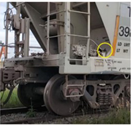
The purpose of retainers is to retain air pressureFootnote 39 in the car brake cylinders, when required, after the train brakes are released and while the air storage reservoirs are being recharged on the cars.
Setting a retainer on a car is a straightforward process that requires the 3-position retainer handle to be manually moved to the HP position. Setting retainers on an entire train is relatively manageable by a lone conductor, because they are visible and accessible from the ground, and the conductor does not need to board each car.
Setting retainers on a stationary train does not provide additional brake retarding force while the train brakes remain applied. Rather, retainers are intended to provide a residual amount of braking force after the train brakes are released. This may help hold the train in a stationary position or control the speed while the air brake system is being recharged.Footnote 40
1.12.2.2 Applying hand brakes
All railway rolling stock is equipped with a hand brake, a mechanical brake device that will secure the car independently of the air brake system. Hand brakes are manually applied (and tightened) by turning the hand brake wheel (Figure 13). This causes the brake shoes to be pressed against the wheel tread surface to prevent the wheels from moving or to retard their motion. The effectiveness of a hand brake is directly proportional to the amount of force exerted by the person applying the brake, which can vary widely from one person to another.
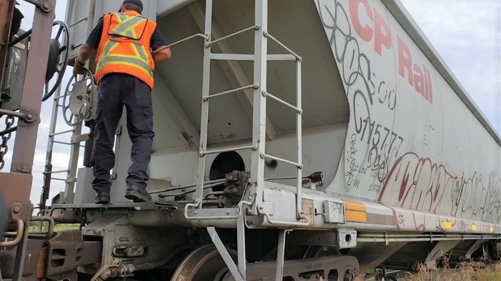
Applying hand brakes requires care in safely negotiating the right-of-way, boarding the car by means of the ladder and grab irons and positioning at the hand brake. Conductors are required to establish a three-point stance before cranking the hand brake wheel clockwise to take up chain slack before applying maximum force on the crank. Variations in car design (i.e., access ladders, grab irons and platforms) require adaptations in the approach to accessing each hand brake crank and dismounting the car.Footnote 41 Overall, applying effective brake force to the car is subject to the operator’s fitness, physical size and individual technique.
In contrast to setting retainers, applying hand brakes requires significantly more time and energy to accomplish correctly. Setting hand brakes on 75% of the cars of a typical loaded grain train is a demanding task for a lone conductor, the success of which is dependent on multiple factors such as experience, physical strength, endurance and technique. In winter conditions on mountain grade, the task is made more difficult by bulky winter clothing and personal protective equipment, coupled with potentially deep snow along the right-of-way; it requires a sustained effort over several hours.
Setting hand brakes on trains situated on main tracks can interrupt rail traffic, with corresponding repercussions on operations across the network. Unlike retainers, however, hand brakes do not rely on the train’s residual BCP for effectiveness.
Although hand brakes were not applied on the occurrence train, in support of this investigation, the TSB conducted mechanical testing and human factors assessment of issues related to hand brake securement of freight trains on mountain grades. Appendix E provides a summary of the results from this study.
1.12.3 Job briefing after the emergency stop
A job briefing between the inbound crew and the trainmaster was held after the emergency stop, as required by the FHOP. The focus was on the shared interpretation of the instructions, which describe actions and considerations required after the emergency stop.
Given the conductor’s relative inexperience, the job briefing took the form of a conversation between the trainmaster and the LE. The trainmaster had dealt with emergency stops in mountain grade a dozen times as a supervisor and once as a conductor. His understanding was that the routine procedure had always been to use only retainers after a first emergency, and to include hand brakes after a second emergency, should one subsequently occur. Hand brakes would also be required to secure trains with mechanical problems that required repairs before resuming their descent.
The LE, in his previous experience as a conductor, had once dealt with an emergency stop on Field Hill. On that occasion, he first applied retainers, but the train speed could not subsequently be controlled and the train had to be put into emergency a second time, at which point hand brakes were applied to secure the train before recovering from the emergency brake application.
During the discussion, the LE mentioned the applied air flow events that he had observed along the way; however, the trainmaster did not perceive this information to be related to the difficulty controlling the train and indicated that he would look into it at a later date during a follow-up review of the LER download.
The trainmaster assessed that the inbound crew could recover the emergency brake application and bring the train to Field. There was no mention of how much time was left on the inbound crew’s work clock. The trainmaster opted for the use of the retainers, set on the HP position, on 75% of the cars (84 cars). Factors such as the rail surface conditions, the extreme cold temperature, and the length of time that the train might remain stationary were not discussed.
The trainmaster’s decision to apply only retainers was not questioned. The job briefing was centred on the use of the FHOP to guide development of a plan to bring the train safely down Field Hill. As such, guidance on retainer use contained in the FHOP was chosen over the use of hand brakes as the intent was to perform a “release and catch” and get underway. The decision to use retainers while recovering the emergency brake application was communicated to the RTC director.
After the job briefing, at about 2230, the conductor began to set the retainers on 84 (75%) of the cars, as decided by the trainmaster and per the FHOP. The task, which was made more difficult by the mountainous terrain, the extreme cold, and the darkness, took about 1 hour. The conductor returned to the locomotive at approximately 2330.
1.13 Crew-to-crew transfer and delays
When the train was stopped in emergency at 2150, the inbound crew was in its last hour of a 10-hour shift, which was scheduled to end at 2230.
The RTC director, on hearing of the situation, recognized that setting retainers and recovering the emergency brake application would take the inbound crew past the end of their shift. As a result, he made the decision to call in a relief crew.
There was already a crew in Field. The members of this crew—an LE, a conductor, and a conductor trainee—were due to come on duty at 2230 to relieve a different train. The director had them reassigned to the occurrence train. The relief crew left Field at the beginning of their shift as scheduled, at 2230, and made their way to Yoho by road vehicle, which took approximately 15 minutes.
A series of circumstances contributed to delaying the relief crew. Because of the train’s location, the relief crew had to travel about 2 miles by rail in a snow removal track unit from Yoho to get to the lead locomotive. Doing pre-checks and readying the snow removal track unit took time, and the delays were compounded when a switch fouled with frozen snow had to be cleaned before the snow removal track unit could get under way. In total, the relief crew was delayed in Yoho for approximately 1.5 hours.
The relief crew arrived at the train at around 0020 and held a job briefing with the inbound crew. The members of the inbound crew then boarded the snow removal track unit to travel to Yoho.
At 0031, in preparation for resuming the trip, the relief LE told the RTC that he was waiting to ensure that the snow removal track unit and all personnel were clear of the main track before cancelling his joint authority with the track foreman; he indicated that, after receiving the “all-clear” confirmation, he would recover the emergency brake application, charge the brake system, and then proceed down to Field. At that point, the train had been stationary on the mountain grade in extreme cold temperatures, ranging from −25 °C to −28 °C, for almost 3 hours.
About 10 minutes later, at 0042, shortly before the snow removal track unit and all on-board personnel were clear of the main track, the train began to roll uncontrolled.
1.14 Train dynamics simulation
The TSB laboratory completed a series of train dynamics simulations using the Train Energy and Dynamics Simulator (TEDS) software program. The simulations examined factors such as speed, acceleration, in-train forces, braking efficiency, and stop distance. It showed the following:
- The average efficiency of the air brake system on the occurrence train was about 60% to 62% of nominal expected values.
- The train derailed mainly due to the high-speed centrifugal forces combined with the lateral force that was generated by moderate in-train buff forces.
1.15 Brake retarding force calculations
Brake retarding force calculations were made to find out how much BCP would have been required to safely descend the average 2.2% Field Hill grade, stop the train with an emergency brake application, and hold the train stationary on the hill.
The train departed Alyth Yard with the brakes cut out on 2 of the 112 cars because the brakes were defective. All calculations regarding braking forces took this into account and were based on 110 cars having operative brakes. The calculated brake retarding force values were numerically rounded to the nearest whole number for simplicity of presentation. For more information on the calculations used to obtain these values, see TSB laboratory report LP014/2022.
The TEDS train dynamics simulation analysis results for braking efficiency and stopping distance verify and support the accuracy of the calculated values.
1.15.1 Brake retarding force required to maintain a constant speed
Given the total tonnage of the occurrence train (approximately 15 000 tons) and the average 2.2% grade, a total retarding force of 630 050 pounds would have been needed to maintain a train speed of 15 mph while descending Field Hill. With the locomotives’ DB set at mid- to high-range (75% of maximum), they would have been providing 220 500 pounds. The remainder of the brake retarding force needed, 409 550 pounds, would have had to be generated by the 110 of the 112 grain cars to maintain a constant speed. Each car would have been required to provide a net retarding force of about 3720 pounds corresponding to a brake shoe force of 12 400 pounds.Footnote 42
The brake effort calculations show that the 112-car loaded unit grain train with 110 cars with operational air brakes would have needed 25 psi average BCP on each operative car to maintain the train speed at 15 mph on the 2.2% descending grade. Theoretically, in the absence of leakage, a BCP of this magnitude can be obtained with a 10 psi brake pipe reduction.
According to the LER data, the brake pipe pressure had been reduced by 19 psi during the descent, prior to the emergency brake application that brought the train to a stop. For a 19 psi reduction, the corresponding theoretical BCP should amount to 40 psi.
1.15.2 Brake retarding force generated by the emergency brake application
At 2148:08, the train brakes were applied in emergency while the train speed was approaching 21 mph on the 2.2% descending grade. The train speed reduced during the next 85 seconds and the head end came to a stop on the main track around Mile 127.46, about midway between the Partridge siding switches. The train stopped after covering a distance of 1815 feet with the train brakes applied in emergency and with a full application of the DBs on the lead locomotive.
Based on a stopping distance of 1815 feet, a retarding force of roughly 923 520 pounds would be required to bring the train to a stop on the 2.2% average descending grade. The 3 locomotives would deliver about 145 850 pounds of retardation due to the application of the independent brakes on the remote locomotives and the retention of full DBs on the lead locomotive.Footnote 43 The remaining 777 670 pounds would have to be provided by the 110 cars with operative brakes.
During the emergency brake application, the retarding force of each car would be roughly 7070 pounds on the wheels or a corresponding brake shoe force of 22 090 pounds. To generate this force, the required average pressure in the brake cylinder on each car would have to be 47 psi.
With the train’s brake pipe and combined reservoir fully charged, an emergency brake application would have theoretically produced an average of 77 psi BCP in emergency.
1.15.3 Brake retarding force required to hold the train stationary after the emergency stop
While the train was stopped with the brakes applied in emergency at Partridge, the total brake retarding force required to hold the train on the 2.2% grade was estimated to be about 593 360 pounds. This force needed to be provided by the 3 locomotives and the 110 cars with operative brakes. All 3 locomotives had full independent brakes applied (72 psi on DP lead, 45 psi on DP remotes), providing a retarding force of roughly 85 060 pounds. The remainder of the retarding force needed (508 300 pounds) had to be provided by the cars (4620 pounds per car).
In order to deliver the required net retarding force of 4620 pounds, the corresponding brake shoe force would have to amount to 14 440 pounds. To generate such a force, the average pressure in the brake cylinder on each car would have to be at least 31 psi, representing an average brake retarding force per car of 40% of the theoretical maximum. If the BCP were to drop below this average, the train would not remain stationary, but would start to roll and accelerate down the grade.
1.16 Air brake system leakage
Train air brake systems must be sufficiently charged with compressed air to operate as designed and to provide the expected amount of brake retarding force when required.
The air brake system on a rail car comprises many components (brake pipe, control valve, auxiliary/emergency reservoir, brake cylinder), each containing many couplings, seals, and gaskets that are prone to air leaks.
Air brake leakage is the leakage that exists in any part of the car air brake equipment from the air hose coupling gasket on one end of the car to the air hose coupling gasket on the other end of the car. It is commonly categorized as brake system leakage and brake pipe leakage. Brake system leakage refers to leakage in the car control valve (CCVs) and the air storage reservoirs; it includes brake pipe leakage. Brake pipe leakage includes leakage in the brake pipe, hose assembly, angle cock, combined cut-out cock and dirt collector, couplings, branch pipe, tee, and flange fittings. Aside from system leakage, additional leakage can result from loss of air from the brake cylinders when the air brakes are applied.
The leakage of compressed air from air brake components is a fundamental problem in cold ambient temperatures. Air brake leakage typically increases with decreasing temperature, and can become quite pronounced in extreme cold ambient temperatures. Many of the seals and gaskets in the air brake system are made of rubber or a composite material. The effects of cold temperatures on rubber can vary, depending on its composition, age, and wear.Footnote 44 Also, cold temperatures are generally known to decrease rebound resilience, making the rubber stiffer and less effective at preventing leakage. This is particularly the case for air brake components with extended time in service, such as CCV gaskets, brake cylinder packing cup gaskets, and old brake pipe flange gaskets.
If the leakage of compressed air becomes excessive, or interferes with the normal operation of the air brake equipment, the brakes may not apply at all, produce less than the expected amount of retarding force, or unintentionally release after a period of time. A car that does not provide the expected amount of braking force does not fully contribute to the retarding force on a train.
1.16.1 Detection of air leaks during brake tests
The leakage of compressed air, and the effects of air leakage, can be detected when freight cars and locomotives undergo various tests and inspections, such as the No. 1 brake test, the single car test (SCT), and the brake cylinder leakage test (which is only performed as part of the SCT).
Brake inspection and various test procedures are covered in the industry-approved AAR Standard S-486,Footnote 45 in TC-approved Railway Freight and Passenger Train Brake Inspection and Safety Rules,Footnote 46 and in CP’s GOIs. These procedures evaluate the functional response of the CCVs for service and emergency brake application commands, as well as the proper release of the brakes.
For more information, see Appendix B – Inspection and testing of air brake systems.
1.16.2 Compensating for air brake system leakage
The air brake system has 2 important features that are designed to compensate for air leakage:
- Quick service limiting valve (QSLV) BCP maintaining: during service brake applications, CCVs maintain the BCP to approximately 8 to 12 psi, regardless of the air brake application in effect. The QSLV functionality is inoperative during an emergency brake application because the brake pipe pressure is reduced to 0 psi.
- Brake pipe pressure maintaining: locomotive automatic air brake valves provide brake pipe pressure maintaining to replenish the loss of compressed air due to leakage effects.
1.16.2.1 Quick service limiting valve brake cylinder pressure maintaining
CCVs incorporate a QSLV, which regulates the BCP between 8 psi and 12 psi in response to a minimum reduction brake application (7 psi reduction in the brake pipe pressure).
The QSLV also has a pressure maintaining feature, which helps ensure that the BCP does not drop below 10 psi during subsequent brake pipe reductions when there is leakage in the brake cylinder, provided the leakage is not excessive. Figure 14 illustrates how this feature works.
In response to a brake application amounting to a 15 psi brake pipe reduction, the BCP will increase rapidly from 0 psi to about 37.5 psi. In the absence of leakage, the BCP will remain at that level and will not trigger the operation of the QSLV.
When there is brake cylinder leakage, however, the BCP will start declining progressively over time in proportion to the leakage rate. In the example shown in Figure 14, for an initial leakage rate of 1 psi per minute, the pressure reaches 35 psi and then drops down to 10 psi in about 20 minutes. When the BCP drops below 10 psi, the operation of the QSLV is triggered. At this point, the BCP is maintained at about 8 to 12 psi, roughly the equivalent of a minimum brake application, thus preventing the car brakes from becoming completely ineffective.
![Quick service limiting valve – braking degradation curve following a brake application (15 psi brake pipe reduction) (Source: A. Aronian and L. Vaughn, “NYAB Brake Cylinder Maintaining Trials Update,” presented at the Air Brake Association Conference, Minneapolis, Minnesota, United States [October 2015])](./images/r19c0015-figure-14.jpg)
Since 2014, new generation CCVs can also include a brake cylinder maintaining (BCM) feature in addition to the QSLV pressure maintaining feature. BCM is available not only for minimum brake applications, but also up to a full-service brake application. More information on this feature is provided in section 1.23.2.
1.16.2.2 Brake pipe pressure maintaining
When there is leakage in the air brake system, whether from the cars’ air brake components or the car-to-car end hose coupling, the air needed to replenish the leaked air comes from the brake pipe. To compensate for the loss of air in the brake pipe, locomotive automatic brake valves have a brake pipe pressure maintaining feature that allows compressed air from the locomotive air brake system to flow into the brake pipe in direct proportion to brake pipe leakage. The air is supplied at a controlled rate to avoid causing an unintended release of the train brakes.
During service brake applications, brake pipe pressure maintaining allows the selected brake pipe pressure reduction to be maintained for long periods of time. This feature allows a train to descend a long mountain grade with the brakes remaining continuously applied as needed. Otherwise, controlling train speed on long descending grades would be difficult.
Without brake pipe pressure maintaining, leakage will cause the brake pipe pressure to continually decrease after the brakes have been applied. This can cause an undesired reduction in brake pipe pressure resulting in an increase in braking effort on the cars, leading to a potential stall condition of the train on the descending grade. Eventually, the brake pipe pressure will drop to 0 psi.
1.16.3 Effects of air leakage on brake application propagation
1.16.3.1 Leakage from the car control valves
When a reduction in brake pipe pressure is made from a locomotive to apply the brakes on a train, the pressure reduction at the locomotive will propagate outward as a pressure wave along the brake pipe. At the same time, the function of the locomotive automatic brake valve will change from pressure-maintaining mode (supplying air into the brake pipe) to pressure-reduction mode (brake pipe reduction).
Once the pressure reduction wave reaches each individual car, the pressure differential between the brake pipe and the auxiliary reservoir will normally cause the CCV balancing valve to allow compressed air to move from the auxiliary reservoir into the brake cylinder to apply the car brakes. However, the presence of excessive air leakage through the CCV service portion can create a localized reduction in brake pipe pressure and interfere with how the CCV responds. Consequently, a small brake pipe pressure reduction, such as 1 to 2 psi, can become diminished and attenuated to a point where it is insufficient to further reduce the pressure drop induced by the leakage. If this happens, the CCV may not respond to the brake pipe pressure reduction and fail to make the desired brake application.
1.16.3.2 Leakage from the auxiliary reservoir
The leakage of compressed air from a car’s auxiliary reservoir is another factor that can negatively impact the total amount of brake retarding force on a train.
The auxiliary reservoir is connected to the brake pipe through the CCV. If leakage from the auxiliary reservoir becomes excessive, to a point where the reservoir pressure drops 1.5 to 2.0 psi below the brake pipe pressure, the CCV will initiate a localized, undesired release of a car’s service brake application.
Auxiliary reservoir leakage is difficult to detect. Since the leakage is typically not audible, it can be easily missed during walking, drive-by, or pull-by inspections, such as the ones performed as part of the No. 1 brake test. Also, under the inspection conditions of the No. 1 brake test, the leakage seldom results in a brake release. For these reasons, a test for auxiliary reservoir leakage is required when performing an automated single car test (ASCT).Footnote 47
SCTs, however, are performed infrequently. In addition, unless the car is equipped with a 4-port adapter connection that allows the SCT apparatus to be connected directly to various parts of the air brake system, there is no quantitative way to directly check for auxiliary reservoir leakage during an SCT.Footnote 48 On cars where the SCT apparatus must be connected to the end-of-car air hose, auxiliary reservoir leakage can only be indirectly assessed through 2 different tests: the multi-step system leakage test and the brake cylinder leakage test.
The multi-step system leakage test (described in AAR Specification S-486, Section 3.5) is used to detect system leakage in general, not auxiliary reservoir leakage in particular. The test measures the overall leakage of compressed air from the car’s brake pipe, auxiliary and emergency reservoirs, combined dirt collector and cut-out cock, and all brake pipe couplings. When leakage is detected, the source could be any of these components. The maximum allowable system leakage rate during this test is 225 cubic inches per minute.
As its name indicates, the brake cylinder leakage test (described in AAR Specification S-486, Section 3.14) is designed to check for brake cylinder leakage and measure the leakage rate. For this test, the brakes must remain applied on the car for 4 minutes and the measured change in BCP due to leakage must be less than 1 psi during the last minute, i.e., 1 psi/minute. If the brakes release during this test, it can provide an indication that the auxiliary reservoir is leaking and that the leakage rate is greater than 145 cubic inches per minute.
Figure 15 shows the effect of auxiliary reservoir leakage on a brake application. In this example, air leakage of 145 cubic inches per minute (the maximum allowable leakage rate from the auxiliary reservoir) was induced in the auxiliary reservoir, a 10 psi brake pipe reduction was made, and the brakes were held for 5 minutes, which was 1 minute longer than the time stipulated in the S-486 brake cylinder leakage test. At the end of this extended-duration test, an undesired brake release occurred.

The occurrence train comprised a mixture of cars, some equipped with a 4-port adapter and some without. It is possible that some of the cars had developed auxiliary reservoir leakage in excess of 145 cubic inches per minute since their last SCT, which went undetected during various field brake tests, leading to an undesired release of the brakes during a service brake application on these cars.
1.16.3.3 Leakage from the brake cylinder
The leakage of compressed air is expected to occur from a rail car, particularly during the colder winter operating season. The leakage rate can vary considerably from car to car depending on several factors. Most of the leakage that may occur will not interfere with the proper operation of the car’s air brake system, nor is it detrimental to the car’s brake effectiveness. The brake cylinder, however, is one air brake component that can be critically affected by leakage. The effectiveness of the air brakes on a car is dependent on the amount of initial pressure that builds up in the brake cylinder in direct response to a brake application command from the controlling locomotive and how long the pressure is retained. The loss of BCP on a car due to leakage will reduce the brake force provided by the car. A brake cylinder that has a significant amount of leakage may completely bleed off in emergency to the point where the brake shoes no longer contact the wheel tread surface, rendering the brakes completely ineffective. A car that does not provide the expected amount of braking force does not fully contribute to the retarding force on a train.
To compensate for leakage, the locomotive automatic air brake system will provide brake pipe pressure maintaining to replenish the loss of compressed air due to the combined leakage that occurs throughout the train. While this is highly beneficial, the brake cylinders on a car are only pressure maintained to a maximum of approximately 8 to 12 psi, regardless of the air brake application in effect. For the vast majority of train operating scenarios (that involve operating trains on grades of less than 1% and other locations where brake applications are only required for a few minutes), this amount of BCP is more than adequate to safely control train speed and stop the train whenever required. However, brake cylinder leakage can be particularly problematic for a heavy-weight train descending a long grade where the air brakes will remain applied for a longer duration. For example, descending the 13.5-mile Field Hill grade at 15 mph requires air brakes to remain engaged and provide a constant amount of brake retarding force for over 52 minutes.
The maximum allowable brake cylinder leakage is 1 psi per minute during a 1-minute test interval, per AAR Standard S-486, Code of Air Brake System Tests for Freight Equipment - Single Car Test. With leakage of air from the brake cylinder, even within acceptable limits, the force exerted by the piston is reduced, resulting in less effective braking on that car.
As an example, at an average leakage rate of 1 psi per minute on each car, the occurrence train would have lost 52 psi of BCP on the descent of Field Hill, which represents an 81.3% loss in braking capacity. Nearing the bottom of the descent, the remaining BCP on the train would have been the equivalent of a minimum reduction brake application (7 psi), which would have been insufficient for the train to maintain the maximum allowable speed of 15 mph.
Brake cylinder leaks are worsened by the deterioration of packing cup gaskets due to aging and wear, as well as by the degradation of the grease lubricating the packing cup system. These leaks are accentuated in cold temperatures, when rubber packing cups, gaskets, and grease harden and contract. At the time of the occurrence, there was no requirement to perform periodic maintenance on rail car brake cylinders. Therefore, brake cylinders could remain in service for long periods of time.
Brake cylinder leakage remains the second highest cause of failure during the single car test, after CCV failures (Figure 16).
![Percentage of single car test failures by cause of failure (Source: E. Gaughan and K. Carriere, “Troubleshooting a freight car brake system” presented at the Air Brake Association annual conference, Indianapolis, Indiana [September 2013]. TSB edited for clarity.)](./images/r19c0015-figure-16.jpg)
1.16.3.3.1 Brake cylinder leakage after an emergency brake application
Wabtec Corporation (Wabtec) performed tests on its 150-car AAR-approved test rack to measure the change in BCP following an emergency brake application with various induced leakage rates.Footnote 49 The brake equipment in the test rack apparatus emulates braking systems on 50-foot cars. Figure 17, derived from these tests, represents BCP degradation for various leakage rates. It describes the evolution of BCP after an emergency application, as all pressures start at around 77 psi at time zero for a fully charged air brake system. The graph shows that, for an initial leakage rate of 0.5 psi per minute, the drop from 47 psi BCP down to 31 psi (the pressure at which the brake force becomes insufficient to hold the occurrence train stationary on the hill) will take about 6600 seconds (1 hour and 50 minutes).

1.16.3.4 Other factors affecting the propagation of air brake applications
Excessive brake pipe leakage can also result in degraded performance of braking effort after a split reductionFootnote 50 when there are extended time intervals between the successive brake pipe reductions. When the pressure maintaining function is active, the air flow into the brake pipe clashes with the brake pipe exhaust, rendering it insufficient for some CCVs to properly sense and respond to any subsequent brake pipe pressure reduction that may follow the initial minimum brake application.
1.17 Monitoring the brake pipe air flow
There are various types of air flows associated with the operation of the air brake system, such as charging flow, release flow, and applied flow. A flow indicator in the locomotive cab provides useful information about these different flow conditions, whether changing or steady-state.
“Charging flow” refers to the flow that occurs while the brake pipe and the air storage reservoirs on the cars are being filled with compressed air. The maximum flow occurs immediately after the LE releases the train air brakes. The flow will gradually reduce and eventually level off to a steady-state value once the brake pipe and car air storage reservoirs are fully charged.
After the brake system is fully charged, any “steady-state flow” that exists indicates the brake pipe is being pressure maintained to compensate for leakage from the air brake system. The amount of flow is proportional to the leakage, and there may be no evident flow if minimal leakage exists.
Under normal circumstances, when brake pipe pressure is reduced to apply the brakes on a train, the air flow value decreases and stabilizes again to a steady-state value.
A rise in air flow when the air brakes are applied is referred to as “application flow” or “applied air flow” and is indicative that one of the following undesired events could be occurring:
- the brakes on the train are releasing (unintentionally); or
- there are other sources of air leakage, notably leakage through the bottom cover exhaust port of the New York Air Brake (NYAB) DB-10 service portion of the CCV and/or leakage through the brake cylinder packing cup gasket.
In the presence of leakage from CCV service portions or brake cylinders, the air flow in the brake pipe will increase rather than decrease when a brake application is made. This will result in the additional flow of compressed air from the brake pipe through these sources of leakage. This will, in turn, trigger the locomotive brake pipe pressure maintaining feature to re-engage to:
- replenish the air that is being leaked through these air brake components; and
- maintain the air pressure in the brake pipe.
Figure 18 shows the 3 different flow conditions associated with the operation of the air brakes.
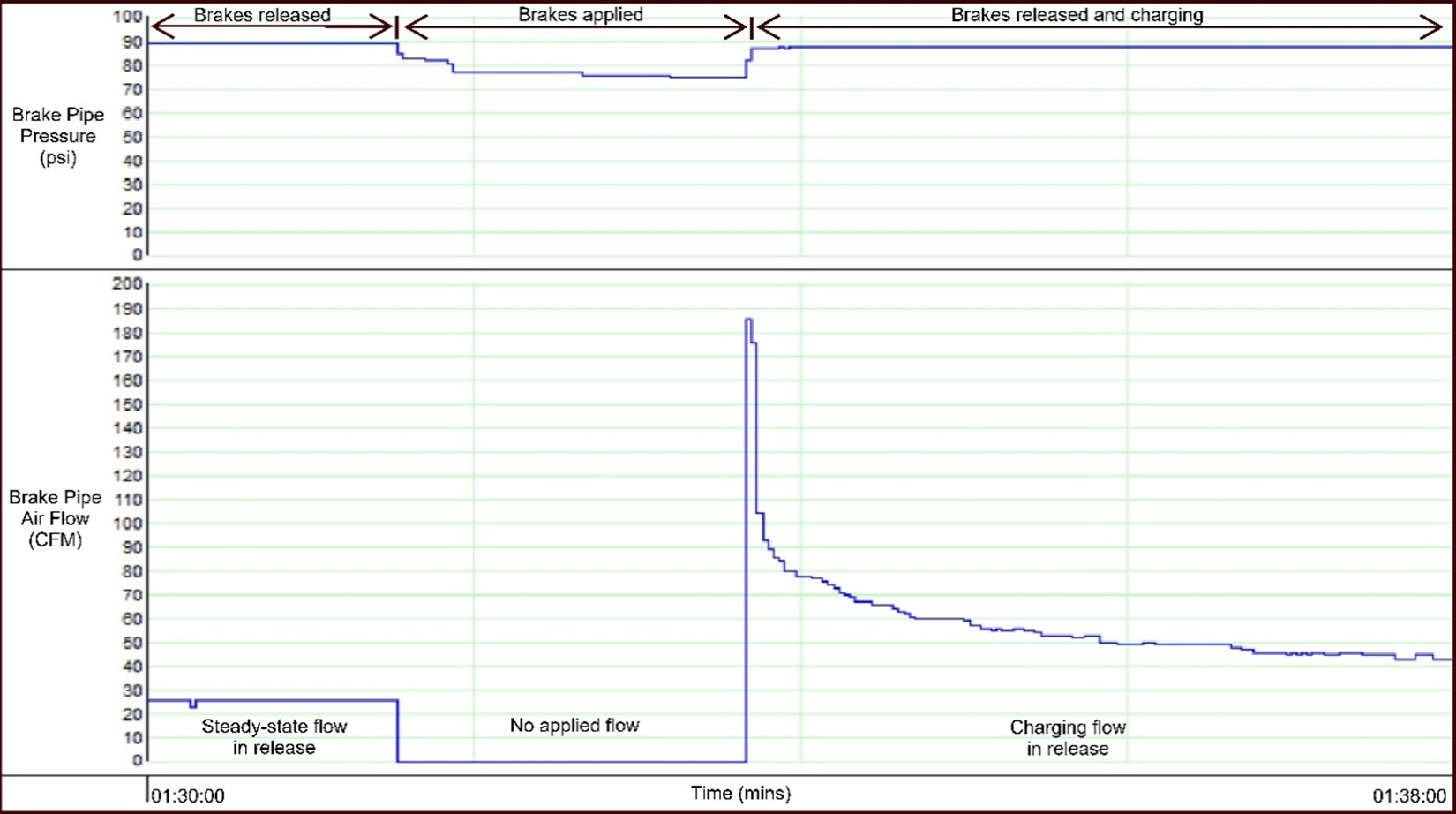
On a DP train, air flows not only from the lead controlling locomotive, but also from operative remote locomotives, which serve as additional air brake pressure control points and provide supplemental sources of compressed air for brake pipe charging and pressure maintaining. The air flow contribution for each of the linked DP locomotives is individually displayed on the DP operations screen that is monitored by the LE. The total air flow being supplied to the train’s air brake system is the combined total coming from all DP locomotive air sources.
1.17.1 Air flow measurements and brake system leakage
Wabtec investigated changes in brake pipe air flow associated with degraded brake system performance.Footnote 51 The investigation involved analyzing selected LER data files, as well as conducting a series of laboratory tests on a 150-car test rack, to examine the response of the air brake system to various leakage conditions. Some of these tests were designed to re-create additional leakage effects that are known to occur on brake equipment that has outlived its effective service life, particularly when operating in cold-temperature environments. This research and analysis effort, based on leakage and air flow assessments, yielded new insight that can be used by industry, and particularly LEs, to better assess leading indicators of and diagnose degraded braking efficiency.
The rack test data confirmed that, for a constant leakage rate, brake pipe air flow decreases when brake pipe pressure is reduced to apply the brakes on a train. The data also confirmed that larger brake pipe pressure reductions will result in a proportionately larger decrease in air flow. As the Wabtec test report states, in part,
The corresponding brake system analogy is that the air flow with the brakes applied – ‘applied flow’ - will be less than the flow with the brakes released – ‘release flow’ for any given condition.Footnote 52
Additional rack tests were conducted to measure the impact on air flow when the leakage rate was increased, to re-create the effect of additional sources of leakage on some of the cars when the air brakes are applied. For the tests, various levels of brake cylinder leakage were induced on 75 of the 150 cars in the test rack. Table 6 shows the change in applied flow associated with various levels of brake cylinder leakage when the 90 psi brake pipe pressure was reduced by 10 psi. These tests were focused on the brake cylinder leakage, and therefore CCVs were not included as a source of leakage, although defective CCVs can also have gaskets that leak and this can vent pressure from the brake pipe, reservoir, and/or brake cylinder.
| Brake cylinder leakage rate (psi/min) | Brake pipe air flow with 10 psi brake application (CFM) |
Total change in brake pipe air flow compared to no leakage (CFM) |
|---|---|---|
| 0* | 8.6** | n/a |
| 1 | 10.7 | 2.1 |
| 2 | 12.2 | 3.6 |
| 5 | 16.1 | 7.5 |
* no brake cylinder leakage
** flow decreased by 1.4 CFM compared to 10 CFM flow with the brakes released and with no leakage
A brake cylinder leakage of 1 psi/minute (the AAR S-486 maximum acceptable limit during an SCT) on 75 of the 150 cars will result in an increase of about 2.1 CFM in applied air flow after a 10 psi brake pipe reduction. Double-digit increases in applied air flow when brakes are applied would indicate excessive brake cylinder leakage, as well as leakage at CCV gaskets.
Figure 19 shows how the demand on brake pipe flow increases to compensate for various rates of brake cylinder leakage. The graph presents results of tests performed on the Wabtec 150-car test rack using a minimum brake pipe pressure reduction (7 psi). If all 150 cars on the rack had leaking brake cylinders at a rate of 3 psi/minute, the total increase in applied air flow would only be about 10 CFM. An air flow increase of this magnitude would be noticeable only when there was already air flow of 20 CFM or greater circulating in the brake pipe (flow below 20 CFM is shown as 0 on the locomotive air flow meter).
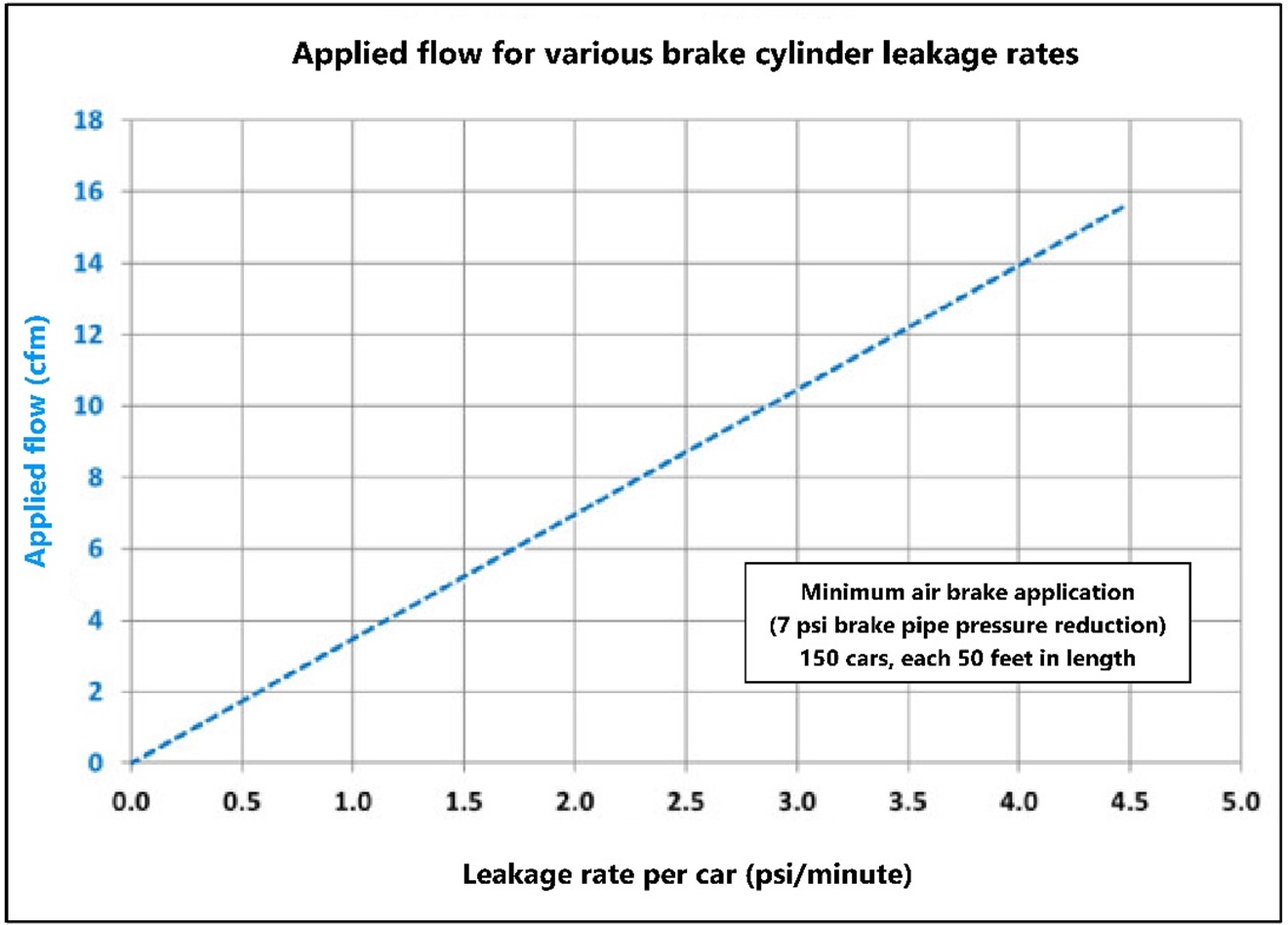
1.17.1.1 Applied air flow readings before the emergency stop
Shortly after departing Alyth Yard, the inbound LE noticed an increase in brake pipe air flow whenever the air brakes were applied (see section 1.17.2 for details). These applied air flow events occurred while bringing the train to a stop for train meets at Keith, Banff, and Eldon. In addition, a sudden and unexpected increase in air flow appeared shortly after making a 7 psi minimum brake pipe pressure reduction as the head-end of the train was starting to descend Field Hill. About 8 minutes later, when the brake pipe pressure was further reduced by 3 psi, another applied flow was observed.
Data from the event recorder on the UP 5359 mid-train remote locomotive show a sudden and unexpected increase in air flow of up to 35 CFM a few seconds after a brake pipe reduction during the initial descent into Partridge. This is illustrated in Figure 20.
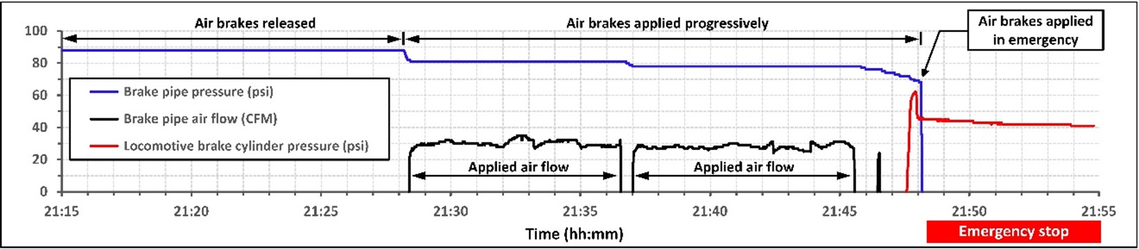
Just prior to the emergency application, 3 incremental brake pipe pressure reductions of 2 psi each were made. However, there was no air flow reading following these reductions because the brake pipe leakage was diminished, due to the following reasons: the brake pipe pressure was reduced; there was not enough time to lapFootnote 53 the brake pipe reduction and activate the pressure maintaining feature to generate increased air flow; and the total flow was less than 20 CFM.
Sources of increased air flow may be due to air brake system leaks, where
[…] brake equipment that has outlived its effective service life may result in generating leakage only when the brake is applied. Defective control valves may vent brake pipe, reservoir or cylinder pressure when applied. Leakage out of brake cylinders will result in a decrease in pressure to the threshold of the quick service limiting valve or the brake cylinder maintaining feature resulting in an increased demand on brake pipe.Footnote 54
1.17.2 Air flow meter
Locomotives are equissssupped with a brake pipe air flow indicator, commonly referred to as the air flow meter (AFM). The AFM displays the measured rate of air flow, expressed in cubic feet per minute (CFM), flowing from the locomotive’s air reservoir into the train’s brake pipe. The AFM is the primary means used by an LE to monitor the movement of air into the brake pipe due to a pressure differential, such as when the brakes are applied, released, or while the brake pipe is being charged or pressure maintained.
The AFM is also used during mandated air brake qualification tests, such as the No. 1 or No. 1A.Footnote 55 The AFM display reading is used during these tests to determine that the total air flow into the brake pipe does not exceed the maximum allowable regulatory limit Footnote 56 when the air brakes are released.
On locomotives equipped with operator display screens, the air flow is shown in a box identified as “Flow” (Appendix A, Figure A5). The value displayed on the screen indicates the amount of air flow going from the locomotive main reservoir into the brake pipe.
When the train brake system is being replenished, the air flow indicator displays a high value, typically higher than 60 CFM. As the system becomes charged, the value displayed comes down, indicating a decrease of flow. The air flow indicator and the LER download will show 0 for any air flow below 20 CFM. Displayed air flow values (20 CFM and higher) normally occur only when the air brakes are released and while the brake pipe and car air storage reservoirs are being replenished.
An LE monitors the AFM for expected changes in air flow that indicate the air brake system is responding to air brake application and release commands. Unexpected changes in air flow can provide an indication about important changes that are occurring in the brake system, whether due to temperature-sensitive leakage effects, or an emergent condition such as an undesired brake release.
Brake cylinder leakage normally goes undetected, unless the LE observes a sudden rise in air flow during a service brake application and understands the implications. The LE has no other indication of systemic brake cylinder leakage, except the fact that the commanded brake application fails to produce the required and expected speed retardation on the train.
1.17.3 Attention and information displays
When operating a locomotive, an LE is required to periodically monitor various operating gauges, including the AFM. The information displayed by the AFM can provide important feedback on braking effectiveness. By design, high air flow events leading to exceedances will not generate exceptional aural or visual caution on the operator display screen.
“Sensory conspicuity” refers to the ability of an object to capture the attention of an observer who does not necessarily expect it to be present or is looking the other way.Footnote 57 Characteristics of warnings, objects, or conditions that are likely to attract an operator’s attention include areas or objects that differ greatly from their backgrounds in terms of brightness, colour, and texture; flickering or flashing stimuli; objects of large size; and objects that are moving.Footnote 58 Red flashing lights and an audible warning are typical characteristics of warnings that are designed to attract attention.
The AAR Manual of Standards and Recommended Practices stipulates that, in terms of design philosophy, the urgency of rail information conveyed by an alarm shall be indicated by the background colour (that is, alarms with red backgrounds are most urgent, alarms with yellow backgrounds are less urgent, and alarms with white backgrounds are the least urgent). Footnote 59
“Cognitive conspicuity” concerns the importance and relevancy of information to an operator’s context,Footnote 60 such as air flow information when braking. To ensure that the most important visual cues for a specific scenario are detected by the operator, the cues need to be easily discriminated as the most relevant and not masked or weakened by other more noticeable cues.
Older, more traditional air flow meters had a design philosophy in line with these recommended practices. They were associated with amber warning lights and auditory feedback from the 26L automatic brake valve, which indicated to an LE when the air flow was increasing above normal parameters. With more modern locomotives, information is presented on a smart display, where the air flow indicator is not associated with any alarms, alerts, or colour coding.
The design of the AFM on the occurrence locomotive displayed a small white number that did not flash, or change colour or prominence, regardless of the circumstances or the flow rate that was displayed. The manner in which data is displayed requires a level of interpretation from the LE to inform follow-on actions if and when required.
1.18 Testing of the recovered cars
After the occurrence, testing was conducted on the 13 cars that remained upright and the tail-end remote locomotive (CEFX 1040) to identify underlying factors that contributed to the loss of braking control on the occurrence train.
The tests were conducted outdoors in cold ambient temperatures similar to the conditions that existed at the time of the occurrence. Additional tests were later conducted in the warmer temperatures of a shop environment.
The 13 cars (Table 7) represented about 11% of the total 112Footnote 61 cars on the occurrence train.
| Car position | Car designation | Year built | Car age (years)* | Make and model of car control valves on occurrence train | Brake cylinder mounting location (model) | Slack adjuster | |
|---|---|---|---|---|---|---|---|
| Service portion | Emergency portion | ||||||
| 1 | SOO 119682 | 1998 | 21 | NYAB DB-10 | NYAB DB-20 | Body | Yes |
| 2 | COER 354009 | 2016 | 3 | Wabco ABDX | Wabco ABDX | Body | Yes |
| 3 | SOO 115417 | 1994 | 25 | Wabco ABDX | Wabco ABDX | Truck (TMX) | Yes |
| 4 | CP 602554 | 1976 | 43 | Wabco ABD | Wabco ABD | Truck (Wabcopac) | No |
| 5 | CP 608497 | 1985 | 34 | Wabco ABD | Wabco ABDW | Truck (Wabcopac) | No |
| 6 | CP 602255 | 1976 | 43 | Wabco ABD | Wabco ABD | Truck (Wabcopac) | No |
| 7 | CP 607911 | 1984 | 35 | Wabco ABD | Wabco ABDW | Truck (Wabcopac) | No |
| 8 | SOO 118863 | 1997 | 22 | Wabco ABDX | Wabco ABDX | Truck (TMX) | Yes |
| 9 | SOO 113918 | 1995 | 24 | Wabco ABDX | Wabco ABDX | Truck (TMX) | Yes |
| 10 | SOO 119626 | 1998 | 21 | NYAB DB-10 | NYAB DB-20 | Body | Yes |
| 11 | CP 604013 | 1977 | 42 | Wabco ABD | Wabco ABDW | Truck (Wabcopac) | No |
| 12 | DME 51387 | 2005 | 14 | NYAB DB-10 | NYAB Wabco ABDW | Body | Yes |
| 13 | COER 354979 | 2007 | 12 | NYAB DB-10 | NYAB DB-20 | Body | Yes |
* Age of car at the time of the occurrence
1.18.1 Outdoor testing
The outdoor testing took place in Banff, Alberta. The locomotive and the 13 cars were placed at the west end of the Banff siding track located at Mile 82.1 of the Laggan Subdivision.
A test plan was developed with the main goal to verify the performance of the air brake system on the locomotive and the cars, and to identify underlying factors that contributed to the loss of braking control on the occurrence train. Various test teams were assembled and included representation from CP and TC.
Tests were performed outdoors in Banff during the 3-day period of 08 February to 10 February 2019. These dates were selected because the ambient temperatures for those days were forecast to be below −20 °C, which would replicate, as closely as possible, the conditions that existed at the time of the occurrence.
A series of tests was performed on the locomotive and the cars assembled as a train and included a visual inspection, a No. 1A brake test, a brake system leakage test, and brake cylinder leakage tests (with and without the retainers applied). A cold-temperature SCT was performed on each car individually.
1.18.1.1 Visual inspection
A visual inspection was performed on the locomotive and 13 loaded grain cars. The inspection confirmed that the air hoses were coupled, the angle cocks between all pieces of rolling stock were all in the fully open position and there was no visible damage on any of the air brake equipment. The empty/load device sensor arms were confirmed in the loaded position on all 13 loaded cars. The wheel tread surfaces and brake shoes were further examined for any evidence of heat stress damage. The wheel tread surfaces showed only medium blueing on less than half of all the wheelsets.Footnote 62
1.18.1.2 No. 1A brake test
A No. 1A brake test using the air flow method was conducted on the locomotive and the cars assembled as a train. The test was successfully completed and served to verify that 11 of the 13 cars met the requirements of the test. The 2 exceptions were CP 602554 (brakes did not apply) and COER 354979 (piston retracted while the test was in progress).
1.18.1.3 Brake system leakage test
A standing brake testFootnote 63 was performed to measure brake system air leakage. The standing brake test requires only 2 measurements, taken at fixed intervals. If the 2 measurements are equal, no leakage exists. If the 2 measurements are different, a leakage rate is calculated.
A simplified brake pipe pressure drop test procedure was used because of the relatively small number of cars involved, the small total volume of compressed air in the brake system, and the cold ambient temperature. The simplified procedure consisted of the following steps:
- charging the brake systems to 90 psi
- applying the air brake on each rail car by making a 15 psi reduction in brake pipe pressure
- waiting for the brake pipe pressure to settle at 75 psi and match the pressure setting on the locomotive’s equalizing reservoir
- closing (isolating) the brake pipe by cutting out the locomotive automatic brake to disable the brake pipe pressure maintaining feature
- monitoring leakage from the brake pipe for approximately 60 seconds
With the source of compressed air cut out, the measured brake pipe pressure had dropped from 75 psi to 72 psi after 60 seconds elapsed, yielding a leakage rate of 3 psi/min.Footnote 64
1.18.1.4 Cold-temperature brake cylinder leakage test
Two key indicators of air brake performance and braking effectiveness on a car are the amount of initial pressure that builds up in the brake cylinder in direct response to a brake application command from the controlling locomotive and how long the pressure is retained.
To gain insight into possible underlying factors that contributed to, or resulted in, a loss of braking control on the train, an extended brake cylinder leakage test was conducted on each of the 13 recovered cars. The test used a script based on available LER data (Table 8), to replicate the train handling actions taken by the LE while the train was descending Field Hill, including the emergency stop at Partridge. The results served to characterize the air brake performance of each of the recovered cars immediately prior to the emergency stop.
| Step | Elapsed time | Brake pipe reduction (psi) | Brake pipe pressure (psi) |
|---|---|---|---|
| 1 | 00:00:00 | Minimum | 84 |
| 2 | 00:07:44 | 8 | 82 |
| 3 | 00:08:29 | 10 | 80 |
| 4 | 00:17:30 | 12 | 78 |
| 5 | 00:18:14 | 14 | 76 |
| 6 | 00:18:48 | 15 | 75 |
| 7 | 00:19:18 | 17 | 73 |
| 8 | 00:19:29 | 19 | 71 |
| 9 | 00:19:44 | 21 | 69 |
| 10 | 00:19:50 | Emergency | 0 |
* The tests began with the air brake released and fully charged to 90 psi.
1.18.1.4.1 Service brake applications
At step 6 of the test script, from a fully charged brake pipe, i.e., 90 psi, a series of brake pipe pressure reductions totaling 15 psi had reduced brake pipe pressure to 75 psi. The measured average BCP for the 13 cars was 21 psi, or 57% of the theoretical maximum value of 38 psi (in the absence of brake cylinder leakage).
The BCP on 5 of the cars (38% of the total number of cars) was between 0 psi and 10 psi. These cars essentially had ineffective air brakes during service applications.
Six of the cars (46% of the total number of cars) did not respond as expected to the successive series of small incremental brake pipe pressure reductions and showed a lower than expected increase in BCP.
The cars with reduced brake pressure would not be expected to have blueing on the wheel surface.
Figure 21 shows how aggregated BCP from the test performed on 08 February 2019, at temperatures of −19 °C to −21 °C, changed over time. From the test measurements, the average BCP for the 13 recovered cars was calculated and plotted over a 20-minute timeframe (solid line in Figure 21). As reference, the theoretical maximum BCP baseline without leakage is shown as a dashed line.
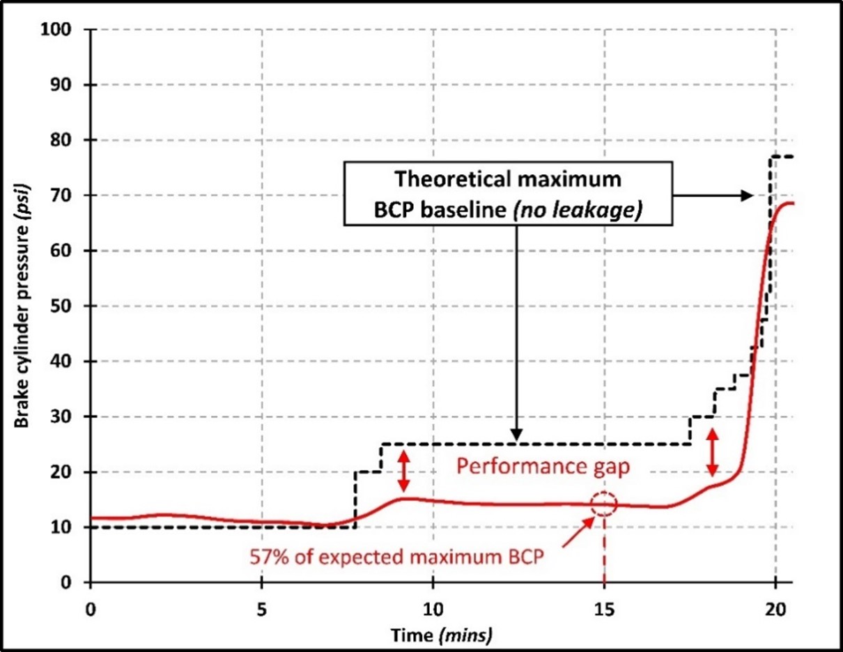
1.18.1.4.2 Emergency brake application
All 13 cars responded to the emergency brake application with increased BCP. The test duration was 180 minutes. The average BCP started at 67 psi (87% of the theoretical maximum) and then declined to 47 psi at the end of the test. After 90 minutes, the average BCP was 69% of the emergency brake theoretical maximum. After 180 minutes, the average BCP was 61% of the emergency brake theoretical maximum, and 9 cars (69% of the total cars) had a BCP of at least 50 psi.
Figure 22 shows how aggregated BCP from the test conducted on 08 February 2019 changed over time during the emergency brake application. This figure further extends the time duration expressed in Figure 21 from 20 minutes to 180 minutes (3 hours). From the test measurements, the average BCP for the 13 recovered cars was calculated and plotted.
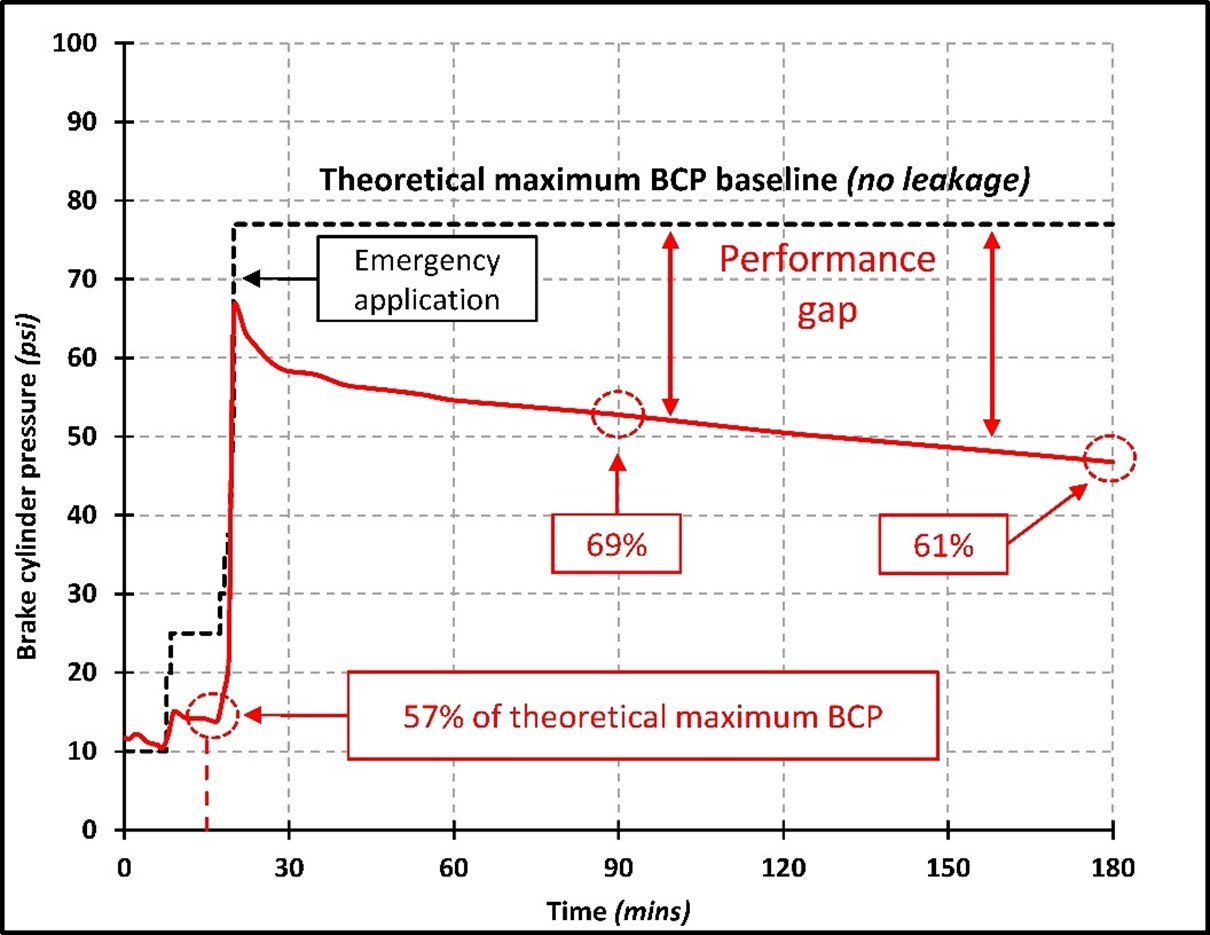
1.18.1.5 Brake cylinder leakage test with retainer
The FHOP require that the retainers be set to the HP position on at least 75% of loaded cars on a westbound freight train stopped in emergency beyond Mile 123.5 of the Laggan Subdivision.
Setting retainers on a stationary train does not provide any additional brake retarding force while the train brakes remain applied. Rather, the retainers are intended to provide a residual amount of braking force after the train brakes are released. This may help hold the train in a stationary position or control the speed while the air brake system is being recharged.
The HP setting is designed to nominally hold up to 20 psi of compressed air in the brake cylinder after the car air brake is released. In a situation where the cylinder pressure is less than 20 psi when the air brake is released, the retainer will initially hold whatever pressure existed at that time.
During the tests performed outdoors in Banff, the leakage of compressed air from the car air brake cylinders was measured with the retainer set up to operate in the HP position. Brake cylinder leakage was measured after releasing an emergency brake application.
At the end of the test (1 hour and 45 minutes), it was observed and recorded that:
- 3 cars (23% of the total number of cars) had a BCP in the 18 to 20 psi range;
- 3 cars (23% of the total number of cars) had a BCP in the 7 to 15 psi range;
- 7 cars (54% of the total number of cars) had leaked down to 0 psi; and
- the average residual BCP for the 13 cars was 50% or less of theoretical maximum (i.e., had leaked down to 10 psi or less.)
1.18.1.6 Cold-temperature automated single car test
A cold-temperature ASCT was conducted on 25 February 2019 between 0230 and 0930. The ambient temperature decreased from −22 °C to −28 °C during that time. The test was performed on each of the 13 cars using an ASCT device. All 13 grain hopper cars failed the test; 12 cars failed because of excessive leakage (brake cylinder or CCV) and 1 car failed the “disconnect test” (receiver check valve leakage test).
In a shop environment, a full AAR S-4027 ASCT would be sequentially followed until all test steps are successfully passed. However, this approach was not practical during the outdoor testing at Banff due to the extreme cold ambient temperatures and the lengthy time that would be involved to repair and retest. A car that did not fully complete a particular test step was considered to have failed the test. A failed test step is indicative of an issue with the air brake system but not necessarily a reduced braking effectiveness. The effect, for example, could be high leakage that will increase recharging time without necessarily having an adverse effect on braking performance.
1.18.1.7 Test of the dynamic brakes on the remote locomotives
Tests were performed on the recovered tail-end locomotive (CEFX 1040) to verify the operational characteristics of the DP system and confirm how the system regulated the brake retarding force produced by the locomotive’s DB and the independent brake in response to an emergency brake application.
The tests confirmed that, because the locomotive was set up for DP remote operation on the occurrence train, it would have lost DB control after the emergency brake application, and its independent brake would have been regulated to a maximum of 45 psi.
This was the expected behaviour:
- On older DP systems, DB holding is not functionally available on remotely controlled locomotives that are linked to the lead DP locomotive via DP radio communication.
- Regulating the independent brake to a maximum of 45 psi on DP remote locomotives in response to an emergency brake application is a legacy design characteristic of the DP system, intended to avoid thermal-mechanical damage to the locomotive wheels.
These test results, while expected, confirmed an important safety detail: when the train stopped in emergency at Partridge, it lost the DB retarding force that had been available on the 2 DP remote locomotives, UP 5359 and CEFX 1040. This amounted to a loss of about 98 000 pounds of DB retarding force per locomotive, or 196 000 pounds in total.
1.18.2 Shop-conducted testing
1.18.2.1 Automated single car test
Additional testing on the 13 recovered cars was conducted at the CP maintenance shop in Port Coquitlam, BC, from 07 May to 08 May 2019. Each car was given a full ASCT while at ambient temperature within the shop.
Test results indicate that 6 cars (45% of the total number of cars) failed the ASCT: 3 cars failed the parts of the test that would result in reduced braking performance, while the other 3 cars failed the parts of the test that would have no influence on the braking performance.
By cross-referencing these ASCT results with wheel temperature data collected prior to the occurrence, the investigation determined that 2 of the cars that failed the ASCT also had cold wheels, indicating that the brake system response on these cars was ineffective. The other cars that failed the ASCT did not have a record of cold wheels.
One car showed marginal cold wheels at the detector located at Mile 111.7 of the Mountain Subdivision, but it did pass the ASCT. Footnote 65 This result indicates the car had brake cylinder leakage that was less than the failure threshold of 1 psi/minute. However, a brake cylinder leakage rate of less than 1.0 psi/min would still result in reduced brake effectiveness if a brake application was held over an extended period.
1.18.2.2 Brake cylinder leakage tests
In addition to the ASCTs, the 13 recovered cars were also tested for brake cylinder leakage during extended periods of time. These tests were conducted to see if the cars had a lower-than-condemnable level of brake cylinder leakage, which could still result in loss of brake effectiveness when brakes on the occurrence train were left applied for an extended period.
The extended brake cylinder leakage tests were conducted to emulate the in-service train brake applications for the occurrence train cars and monitor their brake cylinder leakage rates over an extended period, under normal shop environment temperature range.
During the extended brake cylinder leakage tests, the brakes on 1 car did not apply, and could not be tested further. This same car also showed cold wheels when descending Field Hill after the accident, while en route from Banff to Port Coquitlam.
Four other cars showed various levels of leakage during the retainer tests, losing 40% of the BCP in 6 minutes. These 4 cars did not show any cold wheel while en route to Port Coquitlam. However, their leakages, caused at the retainer piping or brake cylinder level, would have had a negative impact on the BCP retention, resulting in ineffective retainers.
1.19 Brake efficiency based on wheel data
Insight into the train’s brake efficiency before the derailment can be obtained from an examination of the train’s wheels and from a review of wheel temperature data.
1.19.1 Wheel examination
The wheels recovered from the occurrence site were examined for tread blueing.
Tread blueing on railway wheels, which is caused by the frictional heat generated during a heavy or extended brake application, can be used as a qualitative measure to indicate the relative braking force applied to each wheel. The absence of blueing indicates inoperative or ineffective brakes.Footnote 66
Overall, 724 of the 932 wheels (78% of the total) from the train were examined for blueing. An evaluation of the level of blueing and the percentage of wheel tread blued was conducted using the following scale:
- 0 (None) (Figure 23)
- 1 (Very light)
- 2 (Light)
- 3 (Medium)
- 4 (Heavy)
- 5 (Very heavy) (Figure 24)

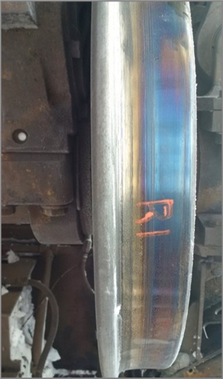
Figure 25 compares the blueing distribution of the car wheels with the blueing of the locomotive wheels. While the car blueing distribution is skewed to the left (less effective car brakes), the locomotive blueing distribution has a bell shape slightly skewed to the right, suggesting that most of the brakes were operative.
Roughly 41% of the examined car wheels did not have any indication of blueing while 11% had very light blueing. Approximately 9% of the car wheels showed heavy or very heavy blueing.
In contrast to the wheels on the cars, the majority of the wheels on the locomotive, almost 64%, had medium, heavy, or very heavy blueing; less than 6% did not have any indication of blueing. High levels of blueing on locomotives can be attributed to the locomotive BCP, which is maintained directly from the locomotive main reservoir whenever the locomotive brakes are applied. When compared to the DP lead locomotive, the 2 DP remote locomotives had less blueing on the wheels, as expected; this is because on the remote locomotives, BCP was being limited to a maximum of 45 psi after the emergency brake application (as opposed to 72 psi for the lead locomotive).
The serial numbers were collected from the inside hub of each set of wheels and were cross-referenced with the car numbers and axle position of each examined wheelset. Figure 26 shows the level of blueing of the wheels on each car and locomotive in the train. The shade of blue depicts the level of blueing observed; no data were available for the cars in yellow. Data were not available for all of the car wheels; therefore, an average value (per car) was used in all cases. Blueing levels tended to be random throughout the train. There were 35 grain cars that had wheels showing no blueing or blueing level 1 (very light blueing).

* The blueing scale on this image is 0 to 3.9 instead of 0 to 5 because the number for each car is the average of all the wheels examined on that car.
1.19.2 Wheel temperature data
The wheel temperature on a car is directly related to the brake shoe retarding force; therefore, it can be used to evaluate brake health. It also serves as a relative measure of braking efficiency when compared to other cars on the same train.
Under sustained application of the train air brakes, such as on a long descending grade, the temperature of the wheels will increase significantly above the ambient temperature. Theoretically, similar cars under similar conditions would exhibit similar wheel temperatures. However, cars providing effective brake force will show elevated wheel temperatures, while those with ineffective brake force would have substantially colder wheel temperatures relative to other wheels on the train.
Wheel temperature data are recorded by wheel temperature detectors (WTD), also known as cold wheel detectors. WTDs use infrared sensor technology to assess the wheel temperatures of passing trains that have been subjected to very recent braking conditions. They flag wheels that are relatively cold compared to train average wheel temperatures.
Sites equipped with WTDs are connected to a communication network, to allow the inspection data from a passing train to be automatically transmitted and stored electronically at a centralized location where they can be analyzed later using automated analysis algorithms.
1.19.2.1 Canadian Pacific’s wheel temperature detectors between Calgary and Vancouver
Initially, wheel temperature data were captured at CP to ensure that air brakes were properly released to prevent excessively high wheel temperatures, which could lead to a wheel failure. However, since October 2008, CP has been using WTDs at selected wayside inspection sites to detect cold wheels and to provide a performance-based assessment of car braking on loaded unit coal trains operating in the BC coal loop.
Although car wheel temperature on coal trains was the initial focus for utilizing WTD technology, the wheel temperature data for all trains passing by a WTD are captured. Scanned wheel temperatures are matched to specific car numbers. CP has 5 WTD sites on mountain grade between Calgary and Vancouver—1 on the Laggan Subdivision at Mile 130.2 and 4 on the Mountain Subdivision: Mile 14.2, Mile 30.2, Mile 95.1, and Mile 111.7.
1.19.2.2 Previous recorded temperature measurements for the occurrence cars
Normally, the wheel temperatures for all 112 cars on the train would have been measured when it passed by the detector located on the Laggan Subdivision at Mile 130.2. However, data were not collected at that WTD for any of the cars on the day of the occurrence because a power outage had rendered it inoperative.
As an alternative source of data, the temperature record was obtained for each of the occurrence train’s 112 cars on their previous loaded trip west to Vancouver. The cars had last been scanned while they were being moved on 1 of 3 separate westbound loaded unit grain trains that had passed by the detectors at Mile 95.1 and Mile 111.7 on the Mountain Subdivision during the last 2 weeks of January 2019 (Table 9). When the WTD measurements were taken the local ambient temperature ranged from −0.5 °C to −3.9 °C—considerably different from the colder ambient temperatures to which the occurrence train was exposed.
| Scan date | Scan time (Pacific Standard Time) | Ambient temperature (°C) | Number of occurrence cars | ||
|---|---|---|---|---|---|
| Mile 95.1 | Mile 111.7 | Difference | |||
| 2019-01-18 | 1304 | 1350 | 46 minutes | −0.8 to −1.2 | 28 |
| 2019-01-19 | 2313 | 2355 | 41 minutes | −0.5 to −0.6 | 12 |
| 2019-01-21 | 1032 | 1113 | 41 minutes | −3.2 to −3.9 | 72 |
The data contained individual wheel temperature measurements for all 8 wheels on each of the 112 cars (896 wheels in total).Footnote 67
While a train is in motion with its air brakes released, the car wheels will typically have a temperature of 35 °F to 50 °F above ambient, due to the friction heat generated by the effects of wheel-rail contact and rolling resistance. When the train’s brakes are applied, the temperature of the car wheels are expected to increase significantly. Wheels that do not contribute to the car’s braking effort remain cold when the brakes are applied; cold wheels are therefore an indication of reduced brake efficiency. A single cold wheel on a car may not necessarily mean that the overall braking performance on that car has been greatly affected. However, the greater the number of cold wheels in a dataset, the greater the likelihood that any given car may have several cold wheels, thus a lower average wheel temperature and a degradation in braking effectiveness.
The number and percentage of cold wheels for the cars on the train were calculated using the data collected at the Mile 111.7 site during the last 2 weeks of January. For this purpose, individual wheels were considered to be cold if their temperature was less than or equal to 70 °F. While a different temperature threshold could have been selected, 70 °F is a reasonable characterization of a categorically cold wheel. In addition, at the time of the occurrence, CP was also using 70 °F to identify cold wheels on coal trains. Based on these calculations, 123 of the wheels (14% of the total 896 wheels) were cold.
The measured temperature for the wheels can be used to further analyze the WTD temperature data, to evaluate overall brake efficiency of the rail cars on the train. In order to depict the entire braking performance of the train, a comprehensive characterization of car temperature data (average of all 8 wheels) using a ranking with several temperature thresholds is required. A ranking system such as the one shown in Table 10 allows the integration of additional criteria and provides a more complete picture of the braking behaviour of the 112 cars.Footnote 68
| Ranking | Temperature threshold (°F) |
|---|---|
| Adequate | Greater than 150 |
| Marginal | From 100 to 150 |
| Cold | Less than 100 |
Cars providing effective brake force will show elevated wheels temperatures while those with ineffective brake force would have substantially colder wheel temperatures relative to the majority of other wheels on the train.
Using data obtained from the WTD at Mile 111.7, Figure 27 shows the average temperature for each of the 112 cars on the train from the head end (left) to the tail end (right). The cars are shown in different colours based on their average temperature, to reflect their respective ranking in terms of brake effectiveness. As the figure illustrates, there were significant differences in car temperature, and several of the cars had an average well below 100 °F, a clear indication that their brakes were either ineffective or completely inoperative.

* Cars in position 27 and 101 had their brakes cut out on the day of the occurrence, and therefore did not contribute to the train’s braking capacity.
** The average car temperatures conveyed in the figure are based on warmer ambient temperatures than on the day of the occurrence.
Table 11 shows the number and percentage of cars and the average temperatureFootnote 69 in the 3 different ranking groups. At the Mile 111.7 detector, 60% of cars had adequate braking, 22% had marginal braking performance, and 18% had inoperative braking systems.
| Ranking | Mile 95.1 detector | Mile 111.7 detector | ||
|---|---|---|---|---|
| Number and percentage of cars | Average temperature (°F) | Number and percentage of cars | Average temperature (°F) | |
| Adequate | 58 (52%) | 201 | 67 (60%) | 201 |
| Marginal | 31 (28%) | 128 | 25 (22%) | 131 |
| Cold | 23 (21%) | 49 | 20 (18%) | 55 |
The car identification markings were used to segment the 112 cars into their fleet of origin. Table 12 presents the car average temperature distribution for all 112 cars segmented by car fleet. The SOO fleet, equipped primarily with a body-mounted brake system, shows the overall highest average car temperature and the largest percentage of cars with a ranking of adequate.
| Car fleet | Car count | Average temperature (°F) | Standard deviation | Number and percentage of cars by car average temperature ranking | ||
|---|---|---|---|---|---|---|
| Adequate | Marginal | Cold | ||||
| SOO | 51 | 175.1 | 67.2 | 37 (73%) | 6 (12%) | 8 (16%) |
| Leased | 21 | 153.6 | 61.8 | 11 (52%) | 6 (29%) | 4 (19%) |
| CP* | 40 | 141.7 | 52.3 | 19 (48%) | 13 (33%) | 8 (20%) |
| Totals | 112 | 159.2 | 62.7 | 67 (60%) | 25 (22%) | 20 (18%) |
* 2 cars in the CP 384000-384999 series and 38 Government of Canada cars in the CP 600000–608591 series
Table 13 compares the braking efficiency of the 13 cars recovered from the accident site to the 99 derailed cars. The table illustrates the number and percentage of cars for the 3 different ranking groups based on the data from the WTD at Mile 111.7. In terms of the percentage of cars, 69% of the 13 recovered cars were ranked as having adequate braking compared to 59% for the 99 derailed cars.
| Car average temperature ranking | 99 derailed cars (%) | 13 recovered cars (%) | Total cars (%) |
|---|---|---|---|
| Adequate | 58 (59%) | 9 (69%) | 67 (60%) |
| Marginal | 23 (23%) | 2 (15%) | 25 (22%) |
| Cold | 18 (18%) | 2 (15%) | 20 (18%) |
1.19.2.3 Cold cars on preceding unit grain trains
Between 01 February and 03 February 2019, 5 westbound loaded unit grain trains passed by the WTD located at Mile 130.2 of the Laggan Subdivision. The relief LE operated one of these trains as recently as the day before the accident and had completed a safety hazard report indicating the need for using a heavier brake application than usual to control train speed.
The wheel temperature data for these trains are listed in Table 14. A significant percentage of cold cars were detected on the trains. The percentage of cold cars climbed from 22% to 56% when the outside temperature dropped from −2.8 °C to −25.6 °C.
| Date | Time | Ambient temperature (°C) | Train | Speed (mph) |
Number of locomotives | Cars | Average wheel temperature (°F) | Number of cold cars (%) |
|---|---|---|---|---|---|---|---|---|
| 2019-02-01 | 2106 | −2.8 | 301-296 | 8 | 3 | 114 | 209.9 | 25 (22%) |
| 2019-02-02 | 1339 | −2.2 | 303-578 | 13 | 3 | 112 | 238.5 | 28 (25%) |
| 2019-02-02 | 1931 | −17.8 | 301-436 | 10 | 3 | 108 | 160.8 | 49 (45%) |
| 2019-02-03 | 1037 | −25.6 | 303-676 | 14 | 3 | 110 | 133.7 | 62 (56%) |
| 2019-02-03 | 1103 | −25.6 | 303-698 | 11 | 3 | 111 | 157.0 | 61 (55%) |
1.19.3 Automated train brake effectiveness study
In 2008, CP began an automated train brake effectiveness (ATBE) study as a means of exploring ways of using WTD technology to identify cars with ineffective brakes on trains in its closed-loop coal service. The work done by CP to use detectors to identify cars with brake system issues was novel in the industry at the time. The system looks at all the train wheels under braking conditions, identifies the normal range of temperature for the cars, and then flags those cars that deviate from the normal range, both hot and cold wheels. These cars are then inspected for stuck or ineffective brakes.
CP coal trains originate in south-eastern BC and travel north to Golden, BC, located around Mile 35 on the Mountain Subdivision. From Golden, trains travel westward and CP used the WTDs at Mile 95.1 and Mile 111.7 on the Mountain Subdivision for this study (Figure 28).
![Mountain Subdivision wheel temperature detector sites used in the automated brake effectiveness study on coal trains (Source: A. Aronian, M. Jamieson, and K. Wachs, “Automated Train Brake Effectiveness Test Process at Canadian Pacific”, proceedings of the ASME/ASCE/IEEE 2012 joint rail conference, Philadelphia, Pennsylvania [17-19 April 2012])](./images/r19c0015-figure-28.jpg)
Note: Detector sites at Mile 95.1 and Mile 111.7 (denoted by H) have both hot box detector and hot wheel detector capability.
On the Mountain Subdivision, the train air brakes will initially be applied to control train speed around Mile 89 and the car wheel temperatures will start to increase. By the time a train passes by the Mile 95.1 detector, the brakes will have remained applied for about 20 minutes and the wheel temperatures will have stabilized. The Mile 111.7 detector site is located about 16.6 miles further away, at which point the air brakes will have remained applied for an additional 40 to 45 minutes. Overall, a train will normally have the air brakes applied for well over one hour while descending the 20 miles of sustained mountain grade.
In 2011, CP received an exemption from TC to test its ATBE technology within its closed-loop coal operations in Canada.Footnote 70 The technology allowed more timely and targeted maintenance practices, which contributed to an overall improvement of coal train air brake performance.
In 2015, TC, the National Research Council of Canada (NRC) and CP initiated a joint research project to assess ATBE as an alternative to or in combination with the No. 1 brake test. The ATBE research examined wheel temperature data from a series of WTDs located at the bottom of long descending grades, where prolonged air brake applications are required to control train speed.
A preliminary scoping studyFootnote 71 was conducted to test whether the NRC could replicate CP’s coal fleet results using the same datasets, and to test the methodology on other bulk commodity train types: potash and grain unit trains. Average car temperature readings (the average temperature of the 8 wheels on a car) for the coal and potash trains showed similar clustering of temperature data. The grain unit train data showed a lower average temperature and greater temperature variation (Figure 29), mostly due to the disparities between the cars (braking system type, age, etc.).
In 2016, preliminary researchFootnote 72 results showed that, compared with other car types, the grain cars had a higher number of cold wheels while braking. Subsequently, as part of an independent research initiative, a comparison of ATBE data and No. 1 brake test results was conducted on a sample of 44 grain trains, each with an average of 112 rail cars per train. ATBE testing identified 695 cars with inoperative brakes (14% defect rate) while the No. 1 brake test identified 5 cars (0.1% defect rate).
A random sampling of 14 of the cars identified by the ATBE testing was sent for an ASCT and inspection. All of the cars in the sample that were identified with ineffective brakes by the ATBE method failed the ASCT.
The final ATBE report was issued by the NRC on 04 October 2018.Footnote 73
1.19.3.1 Applying the automated train brake effectiveness methodology to grain trains
At the time of the occurrence, CP had a waiver from TC authorizing the use of ATBE to assess the effectiveness of the brakes, which was applicable to the coal fleet exclusively. Therefore, there were no formalized criteria to set specific thresholds for identifying grain cars that deviate from the normal range of wheel temperature. Consequently, a slightly different approach was required to assess and categorize the wheel temperature data for the cars on the occurrence train.
Coal cars and grain cars are similar in terms of loaded weight and braking characteristics. For instance, on the occurrence train, each loaded grain car weighed 129 tons on average, while a loaded coal car weighs about 143 tons on average, a difference of only 10%. The tons per operative brake characteristics of the occurrence train were also quite similar to a typical loaded coal train.
These similarities provided the rationale for adapting the coal train ATBE methodology to grain cars.
The ATBE methodology uses train average temperature and standard deviation (SD)Footnote 74 as criteria to identify cold cars. Therefore, these values were calculated for the 112 cars on the train based on WTD data collected at Mile 95.1 and Mile 111.7 in the last 2 weeks of January 2019 (Table 15).
| Wheel temperature detector site | Car temperature (°F) | |||
|---|---|---|---|---|
| Highest | Lowest | Average | Standard deviation | |
| Mile 95.1 | 295.3 | 26.3 | 149.7 | 65.7 |
| Mile 111.7 | 283.8 | 23.0 | 159.2 | 62.7 |
In terms of overall air brake performance of a train, the most representative metrics in Table 15 are the overall average temperature and the SD. The average temperature and the SD values need to be correlated with values that are considered to represent acceptable braking performance for the conditions under which the data were obtained. Typically, train-specific results would be compared and ranked against a large representative baseline sample population of similar trains. However, there were no ATBE data for grain cars, and hence data from coal trains were used.
As shown in Table 15, an average temperature of 159.2 °F and an SD of 62.7 °F were obtained at the detector site at Mile 111.7 of the Mountain Subdivision. In comparison, WTD data presented in the ATBE paperFootnote 75 showed an average wheel temperature of 242 °F and an SD of 50 °F for loaded coal trains going over the same detector.
The ATBE rules at CP considered a coal car to have ineffective brakes if the temperature of one wheel was less than or equal to
- 70 °F, and
- 3 SDs from the overall average wheel temperature for the train.
However, the criterion of less than 3 SDs would give a negative threshold value in the case of the cars that comprised the occurrence train, due to the low average car temperatures and the large spread of temperatures between cars, as compared to the WTD data for coal trains. Consequently, for the purposes of this investigation, a car average temperature threshold of 1.5 SDs from the average is more meaningful and provides reasonable representation of the braking performance. The use of 1.5 SDs is one of the methods recommended by the NRC in its preliminary scoping study of ATBE. For the occurrence train, 1.5 SDs from the overall average wheel temperature corresponds to 65.2 °F.
Using the modified criteria (70 °F and 1.5 SDs), the analysis of the entire temperature dataset collected at the Mile 111.7 site determined that 111 wheels (12% of the total 896 wheels) were cold.
Figure 30 is a histogram of the wheel distribution by temperature range for all 896 wheels, based on data obtained from the WTD at Mile 111.7 of the Mountain Subdivision. The large double-headed arrow shows the band of temperatures that are within 1.5 SDs (i.e., 94.1 °F) on either side of the average wheel temperature (i.e., 159.2 °F).
In this figure, wheels below 80 °F (145 wheels) are shown in the dashed rectangular box on the left. Of these, 111 met the criteria for cold wheels (less than 70 °F and 1.5 SDs, i.e., 65.2 °F).
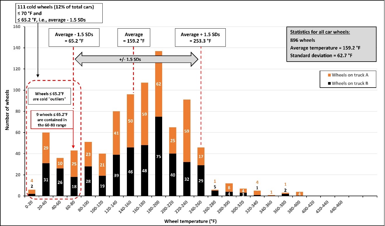
1.20 Brake shoe friction fade
The investigation considered the possibility of brake shoe friction fade playing a role in the occurrence.
The friction between the brake shoe and the wheel tread is critical to maintaining the required brake retarding force. The brake shoe coefficient of friction depends on several factors such as shoe surface condition, the rotational speed of the wheel, applied braking force, and duration of the brake application. Contaminants such as snow and ice can reduce the coefficient of friction. Brake shoe friction fade, also known as friction fade, can also alter this coefficient of friction, resulting in a degradation of retarding force.
When the automatic brake is applied, heat is generated at the brake shoe/wheel tread interface. The amount of heat generated is proportional to brake horsepower (BHP),Footnote 76 which itself is proportional to speed and brake retarding force. Heavier cars need a higher retarding force for speed control when descending grades and therefore generate higher temperatures and are exposed to higher BHP.
When the thermal capacity of a brake shoe is exceeded for a sufficient length of time, the coefficient of friction may be lowered and friction fade may occur. When excessive heat build-up occurs, the coefficient of friction between a brake shoe and the wheel tread is lowered, leading to a significant loss of brake retarding force. Studies have shown that friction fade does not occur on 36-inch-diameter wheels, such as the wheels on the occurrence train, when BHP is 30 or less.Footnote 77
1.20.1 Friction fade on the train
From Stephen (where the initial brake pipe reduction occurred) to the emergency application of the brakes, the speed of the train varied from 8 mph to 21 mph. Using the brake retarding force of 409 550 pounds calculated in section 1.15, and given a speed varying from 8 mph to 21 mph, the resulting BHP would have been between 10 and 26. Therefore, brake shoe friction fade was not likely a factor while bringing the train to a stop.
However, during the uncontrolled movement, the train accelerated to 53 mph. On those cars with effective brakes, the conditions necessary for friction fade would have existed: at this speed, the BHP would have exceeded 30 and could have reached as high as 67.
1.20.1.1 Speed profiles for the mid-train and tail-end locomotives
To further assess the impact of friction fade and how it contributed to the high rate of speed reached by the uncontrolled movement, the LER speed data were analyzed. The data represent the actual performance of the occurrence train in response to all of the specific operating conditions and dynamic variables acting on the train.
From the time the train started to roll on its own with the train brakes applied in emergency, up to when it derailed at a speed of about 53 mph, about 8.5 minutes elapsed. Figure 31 shows the LER speed profile plotted over this time period for the DP mid-train locomotive (UP 5359) and for the DP rear locomotive (CEFX 1040). The data from CEFX 1040 show that the speed of the rear locomotive dropped rapidly from about 48 mph to 0 mph when the rear portion of the train derailed. The data from UP 5359 show that, about 23 seconds later, the speed of the mid-train locomotive dropped rapidly from 53 mph to 0 mph as the middle portion of the train derailed. The data from the UP 5359 are shown as a stepped line because the LER captured speed as an integer value, whereas the CEFX 1040 LER captured speed to 1 decimal point.
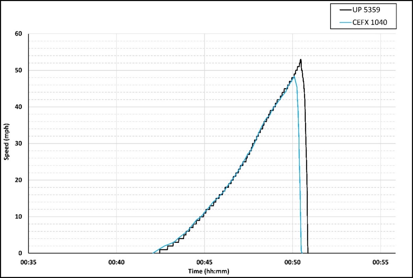
1.20.1.2 Friction fade for various accelerations
There are 3 key fundamental variables that significantly influence train speed during an uncontrolled movement: net grade force, net BCP, and brake shoe coefficient of friction. If the coefficient of friction degrades due to friction fade, the acceleration of the train will increase in proportion to the change in friction.
A close examination of the speed data shown in the graph above indicates that the rate of change in speed did not remain constant throughout the uncontrolled movement. To quantify this, 3 speed ranges were identified that each had a similar characteristic related to the rate of change in speed. For each range of speeds, an average acceleration in mph/min was calculated to determine how the acceleration changed during the uncontrolled movement. The results indicate 3 distinct changes in acceleration occurred, each specific to a range of speeds. Table 16 shows the 3 speed ranges and the calculated average acceleration of each speed range.
| Speed range (mph) |
Duration | Acceleration (mph/min) |
|---|---|---|
| 0.0 to 6.1 | 2 mins 1 sec | 3.3 |
| 6.1 to 19.1 | 2 mins 23 secs | 5.5 |
| 19.1 to 53.0 | 4 mins 2 secs | 8.0 |
The 3 accelerations are illustrated in Figure 32 as 3 trend lines superimposed on the speed plots from Figure 31.
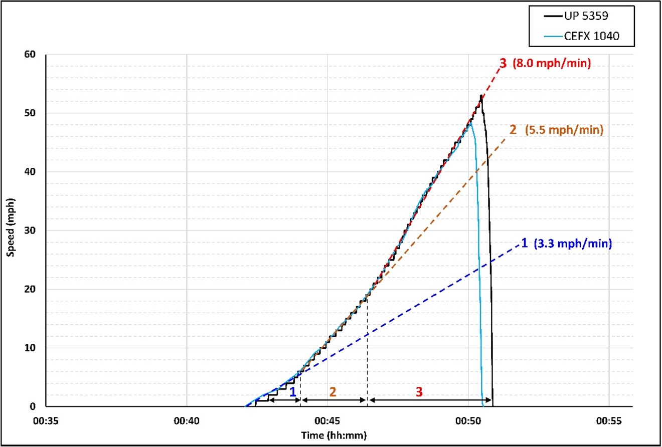
The trend lines are labeled 1 to 3 and indicate a higher acceleration with increasing trend line number:
- Trend line 1 illustrates that the train had a constant acceleration of 3.3 mph/min during the first 2 minutes and 1 second while the speed increased from 0.0 mph to 6.1 mph. Throughout this speed range, a higher brake shoe friction is inherently expected. Thus, the acceleration trend line is not as steep as it is for trend line 2.
- Trend line 2 illustrates that the acceleration remained constant at 5.5 mph/min during the next 2 minutes and 23 seconds while the speed increased from 6.1 mph to 19.1 mph. In this speed range, the initial amount of brake shoe friction will decrease and, in the absence of friction fade, is normally expected to start levelling out and gradually reach a near constant amount of friction.
- Trend line 3 illustrates that the acceleration remained constant at 8.0 mph/min during the last 4 minutes and 2 seconds while the speed increased significantly from 19.1 mph to 53 mph, at which point the lead locomotive derailed. During this time, the wheel tread surface and brake shoe temperatures would have quickly increased, and continued to increase (on the cars that were providing a high brake shoe force, i.e., the cars with a BCP of 50 psi or more), creating the conditions that lead to friction fade.
The analysis results, in summary, show that friction fade would not have been a significant factor in the first 4.5 minutes during which the speed of the uncontrolled movement increased from 0 mph to 20 mph. However, once the speed of the uncontrolled movement reached about 20 mph, a significant (45%) increase in acceleration is evident, represented by the difference in trend lines 2 and 3. The faster rate of change in speed above 20 mph, acceleration trend line 3, is attributable to friction fade.
1.20.1.3 Calculated speeds for the train with and without friction fade
Additional analysis was done to estimate the speed trajectory that the uncontrolled movement would have followed had friction fade not occurred.
The investigation determined that the head-end portion of the occurrence train derailed within a few seconds after the mid-train portion. Thus, the maximum speed attained on the lead locomotive would have been similar to the maximum speed of the mid-train locomotive. Therefore, the LER speed and distance data from the mid-train locomotive was used as surrogate data to determine the speed of the lead locomotive from the time the train started to roll on its own, up to when it derailed at a speed of about 53 mph. Additionally, the theoretical speed of the train without friction fade, from 19.1 to 53 mph, was extrapolated by using the average acceleration of 5.5 mph/min calculated for the pre-fade speed range of 6.1 mph to 19.1 mph and applying it to the friction fade range.
Figure 33 shows speed versus distance plots for the lead locomotive with, and without, friction fade. The values for the actual speed and distance traveled were captured by the UP 5359 LER, but with the distance offset by 3349 feet to represent the actual location of the lead locomotive in the train (instead of the mid-train locomotive). As the figure illustrates:
- In this occurrence, the lead locomotive attained the maximum speed of 53 mph just before arriving at the Kicking Horse River bridge; friction fade was present and the train was accelerating at 8.0 mph/min.
- Had friction fade not been present, the increase in speed would have occurred at the slower rate of 5.5 mph/min, and the train’s speed at the Kicking Horse River bridge would have been 44.4 mph, a reduction of 8.6 mph.
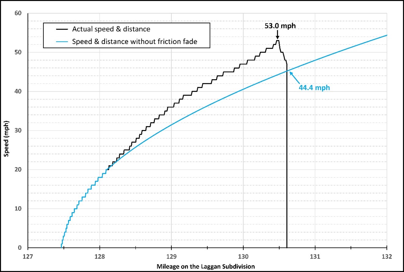
TSB calculations determined that the theoretical tip-over speed threshold on a 10° curve for a locomotive would be about 53.9 mph.
In the 02 December 1997 occurrence in which CP grain train No. 353-946 rolled uncontrolled at high speed on Field Hill, the 2 head-end locomotives and first car successfully negotiated the 9° curve at Mile 134.4 while travelling at about 47 mph.Footnote 78
1.21 Car control valve malfunction in extreme cold temperatures
CCVs respond to decreases and increases in brake pipe pressure by applying and releasing/recharging the brakes of the cars they control. They are composed of 2 portions—a service portion and an emergency portion—as well as the pipe bracket where the portions are connected.
In extreme cold environments, the internal rubber gaskets and O-rings of the CCV can shrink, resulting in air leakage. Rubber components on older CCVs are especially susceptible to leaks in extreme cold temperatures.
1.21.1 Worn rubber seals
Teardowns and testing of selected service (NYAB DB-10) and emergency (NYAB DB-20 and Wabtec) portions from the January 2018 loss of control occurrence on CN’s Luscar Industrial SpurFootnote 79 showed that worn and deteriorated rubber seals resulted in excessive leakage from the CCVs during extreme cold temperatures. The leakage resulted in the valves malfunctioning in response to service and emergency brake applications. These situations would only occur at extremely low operating temperatures. ASCTs conducted before the occurrence on those service portions during periodic testing and maintenance at temperatures above 4.4 °C (40 °F) had not identified valves that needed to be removed from service due to this condition.
1.21.2 DB-10 car control valves: Association of American Railroads circular letter
In 2013, NYAB investigated concerns regarding malfunction of the DB-10 service portion during brake applications in extreme cold ambient temperatures. The results of the investigation were issued in NYAB General Letter GL-490, Cold Temperature DB-10 Auxiliary Reservoir Leakage, dated 09 September 2013.Footnote 80 The letter was distributed to the rail industry by the AAR through Maintenance Advisory MA-143 (Circular Letter C-12027) on 25 October 2013. The circular is provided in Appendix F.
The NYAB general letter described a condition characterized by increased brake pipe air flow and auxiliary reservoir leakage after applying the brakes. The increased air flow was caused by leakage from the bottom cover exhaust port of the DB-10 service portion due to a worn rubber seal (Figure 34).
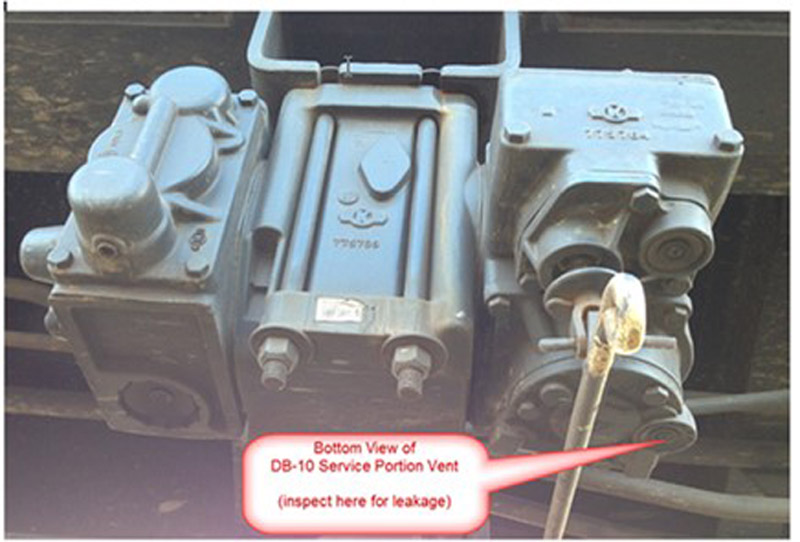
The following elements were outlined in the letter:
- Individual cars with excess leakage from the CCV might not be able to maintain a service brake application (potentially resulting in an undesired release).
- The excess air flow may result in increased brake application on the rear portion of the train and result in dragging brakes.
- SCTs conducted at temperatures above 40 °F (4.4 °C) will not identify valves that need to be removed from service due to this condition.
- DB-10 CCV portions subject to high vibration in high-mileage service may develop low-temperature leakage at some point in time above 13 years of age.
- Trains experiencing high air flow with the brakes applied should be inspected for the presence of suspect DB-10 service portions.
On 01 November 2018, NYAB issued General Letter GL-49003 to reinforce the message presented in GL-490 and to include DB-20 emergency portions. The following revised corrective actions were recommended:Footnote 81
- Any DB-10 service portion experiencing one or more of the described symptoms should be removed from service as soon as practical and refurbished per NYAB Maintenance Specification NYR-332.
- In addition, any DB-20 emergency portion partnered with the above removed DB-10 service portion that is original equipment manufacturer (OEM)/“clean, oil, test and stencil” (COT&S) date-coded the same age, is older or has no legible date code should be removed.
1.21.2.1 Canadian Pacific Bulletin CPSB048-13
After the distribution of NYAB General Letter GL-490 by the AAR through Maintenance Advisory MA-143 (Circular Letter C-12027), CP issued Bulletin CPSB048-13 in November 2013 as a maintenance advisory to train operations staff (Appendix G). The 1-page bulletin described functional behaviour related to specific control valve types in cold operations, with a discussion of symptoms and effects, stating in part,
while enroute, should the Locomotive Engineer notice an increase in flow during a brake application, the crew must advise the RTC. The RTC will notify the Mechanical desk in the Operations Centre, who will arrange for an inspection of the train at a suitable Mechanical location.Footnote 82
Bulletin CPSB048-13 was rescinded in 2014 as it had been issued to the crews for information purposes and it was not deemed necessary to reissue it or include its contents in the monthly operating bulletin indefinitely. CP still expected LEs to monitor brake pipe air flow regularly; however, they were no longer required to report applied air flow events to the RTC.
1.21.3 Weeper port issues on DB-10 service portions
Brake pipe leakage has a strong effect on the overall performance of train brake application signal propagation. For the brakes to apply, the brake pipe must be reduced by 1.5 to 2 psi below the auxiliary reservoir pressure. The brake pipe pressure drop must be sufficiently rapid and of sufficient magnitude to overcome the stabilizing effect of the weeper port. The weeper port is a very tiny passage in the service portion that connects the brake pipe to the auxiliary reservoir. It provides stability to prevent normal fluctuations and gradual changes in brake pipe pressure from triggering an undesired brake release. Furthermore, the brake pipe pressure reduction must generate a steady and appreciable pressure differential for it to be sensed by the CCV.
Modern electronic air brake systems on freight locomotives have made it possible to implement and control brake pipe reductions to within 1 to 2 psi. However, the same response is not necessarily available on the CCVs of older freight cars, which are still very common throughout North America.
Various field and laboratory tests were conducted by CCV manufacturers and the AAR between 2002 and 2004 to evaluate the response of some CCVs to small stepped brake pipe reductions.Footnote 83 The tests indicated that 1 psi stepped brake pipe reductions following a minimum brake reduction resulted in almost no additional BCP build-up on some freight cars. The tests also incorporated a few minutes of wait time between each stepped reduction, to give enough time for the CCVs to respond to the brake pipe reductions. Most cars did not respond to the incremental 1 psi brake pipe pressure reductions, and the dwell time between reductions also resulted in the auxiliary reservoir pressure being depleted into the brake pipe through the weeper port. As a result, no additional BCP developed during the stepped reductions and through the incremental depletion of the auxiliary reservoir pressure.
These tests showed that a train operating with a series of such CCVs would not achieve expected brake performance and an increase in retardation in response to small incremental stepped brake pipe pressure reductions. The CCV design most susceptible to this condition was the one that included a DB-10 service portion manufactured by NYAB before 2005. In 2005, the AAR Specification S-464 was changed to address this issue on new and reconditioned service portions.Footnote 84 Therefore, the condition would only be present on DB-10 service portions that had not been reconditioned since then. In the occurrence train, 47 grain cars were equipped with NYAB’s DB-10 service portions, 27 of which (24% of the train consist) had old units that were never reconditioned.
1.21.4 Examination of the train’s car control valves
Overall, 86.6% of the portions were recovered from the wreckage and were examined. Due to the extensive damage sustained by the derailed cars and their rolled-over positions at the derailment site, only 25% (49 of 194) of the examined portions were matched to the car on which they were installed at the time of the occurrence.
1.21.4.1 Make and model of car control valve portions
The recovered portions originated from 2 main manufacturers—Wabtec and NYAB (Table 17). There were 3 Wabtec models: ABDX, ABDW and ABD. The ABDX service portion is the newest valve model and was introduced in 1989, Footnote 85 while the ABDW emergency portion was introduced in 1976. Footnote 86 The 3rd model of Wabtec valves was the ABD model, introduced in 1962. Footnote 87 The NYAB portions were the DB-10 service portion and the DB-20 emergency portion that were approved by the AAR in the early 1990s.
| Make | Model | Number of examined portions | Percentage of all examined portions |
|---|---|---|---|
| Wabtec | ABDX | 42 | 21.7 |
| ABDW | 13 | 6.7 | |
| ABD | 51 | 26.3 | |
| Total Wabtec | 106 | 54.6 | |
| NYAB | DB-10 | 47 | 24.2 |
| DB-20 | 41 | 21.1 | |
| Total NYAB | 88 | 45.4 |
1.21.4.2 Date of manufacture
None of the CCV portions had any direct stencil providing information about their age or date of manufacture. Just over 60% (119 of 194) of the recovered valve portions had legible serial numbers. Less than 25% of the recovered Wabtec portions had OEM identification tags (OEM ID tags).
AAR data show that only 30% of the valves in the railway industry are currently bar-coded and entered in the AAR database. The AAR issued new requirements in 2016 to have bar codes on each valve portion to indicate the date of manufacture and of last reconditioning.
According to the age ranges provided by the manufacturers, 78 portions on the occurrence train with known dates of manufacture were older than 15 years (Figure 35). Wabtec introduced OEM ID tags and serial numbers only after 1996, which suggests that the Wabtec portions with no OEM ID tags were likely manufactured prior to that date. When the Wabtec portions with no OEM ID tags are added to the 78 portions mentioned above, the total number of portions older than 15 years is 142 (63% of the total).
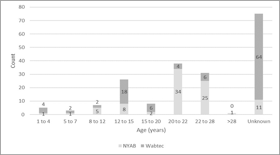
1.21.4.3 Date of last reconditioning
About 46% of recovered portions (89 units) had no information concerning their last reconditioning COT&S dates. Out of the valves manufactured by Wabtec, 40 portions (38%) had not been reconditioned over the last 15 years.
The train consist included 47 grain cars equipped with NYAB DB-10 service portions, of which 36 were manufactured before 2005, including 27 (24% of the train consist) that were never reconditioned.
Maintenance requirements for CCVs at the time of the occurrence were condition-based, where the cars were required to undergo an SCT test at least every 60 monthsFootnote 88 using an automated or a manual SCT device. Cars that failed this SCT required CCVs to be replaced based on the type and nature of the failures. Previously, CCVs were required to be reconditioned or replaced on a time-based regime. In the 1930s, this interval was every 3 years. It gradually increased to 16 years between the 1960s and the late 1980s. It was eventually eliminated in the 1990sFootnote 89 and replaced by the AAR condition-based replacement policy.Footnote 90
1.21.5 Actions taken by the Association of American Railroads
Following a 10 January 2018 occurrence at Luscar Industrial Spur in Leyland, Alberta, in which a freight train rolled uncontrolled while proceeding down a mountain grade, Footnote 91 and in response to a number of other occurrences in Canada and the U.S., the AAR looked into the issue of leakage from older CCVs in extreme cold temperatures.
The AAR determined that old rubber parts inside CCVs cannot be depended upon to prevent leakage in extreme cold temperatures. As a result, the AAR has defined conditions under which CCVs should be replaced due to their age and exposure to service conditions in cold temperatures. Circular Letter C-13556 was issued to that effect on 30 April 2020, seeking industry comments, with a target implementation date of 01 July 2020. This new requirement applies to freight cars with CCVs older than 13 years since their last COT&S date, which will be working north of the 37th parallel during winter months. The AAR has also designated a new and unique repair code (WMC 1K) to identify the replacement of such over-age CCVs.
The entire text of the July 2021 revision is listed as follows:
[…]
- When Car is on Shop or Repair Track for Any Reason
- Vacant
- As Noted Below:
- Service and/or emergency portion control valves with a manufacture or recondition date (whichever is later) of 13 years may be renewed, and if over 14 years must be renewed for over age cause on a car if:
- (1) The car will be part of a unit train service carrying coal, grain, High Hazardous Flammable Class 3 Commodity, or Toxic Inhalation Hazard (TIH/PIH) service; and
- (2) Operates any part of its route in territory above the 37th parallel for any length of time within the date range of November 1st thru April 1st
- (a) Car does not need to be operating north of the 37th parallel at the time of renewal
- (b) Renewal may occur at any point throughout the year Footnote 92
The issue of renewing older NYAB’s DB-60 CCVs was introduced as a bill by the U.S. House Committee on Transportation and Infrastructure (T&I) in 2020, and was folded into the Moving Forward Act. The bill called for trains operating north of the 37th parallel to renew any DB-60 CCV manufactured before 01 January 2006. The requirement would have come into effect on unit trains starting on 01 August 2022, and on all other merchandise trains starting on 01 August 2024. The bill called for the U.S. Government to track the progress of phasing out these brake valves and the number of trains still operating with them.Footnote 93 After the January 2021 change in U.S. Administration, this bill was no longer in motion, but it had gained high importance for the AAR to implement changes to the Field Manual Rule 4, to require time-based renewals of old CCVs in unit train operation.
1.22 Comparison between the recovered cars and the derailed cars
Some of the fundamental statistics (age, CCVs, maintenance history, WTD data) between the 13 recovered cars and the 99 derailed carsFootnote 94 were compared to determine to what extent the test results of the 13 recovered cars could represent the braking performance of train 301-349 as it operated through Partridge at the time of the occurrence.
As Figure 36 shows, the recovered cars were similar in age to the derailed cars. This was confirmed by an independent-samples Student’s t-test, which showed that there was no significant difference in the ages of recovered cars (M=26.1 years, SD=12.8 years) and derailed cars (M=27.9 years, SD=10.1); t (107)=0.602, p = 0.549.Footnote 95
1.22.1 Car control valves
Of the 13 recovered cars, 4 were equipped with NYAB DB-10 service portions. One of those 4 cars had the DB-10 service portion replaced in 2010. The other 3 cars (23% of the total recovered cars) were susceptible to leakage; 1 had a 12-year-old valve and the other 2 had DB-10 service portions that had not been reconditioned in the last 13 years.Footnote 96
Similarly, 47 grain cars in the train were equipped with NYAB DB-10 service portions, of which 27 (24%) had old units that were never reconditioned.
Of the 13 recovered cars, 5 (38%) were equipped with the oldest version Wabtec ABD service portions. Similarly, 51 cars out of 112 cars (45%) in the train were equipped with ABD service portions.
1.22.2 Wheel temperature data
Data from the Mile 111.7 WTD for the 13 recovered cars and the 99 derailed cars destroyed in the derailment were compared. Their summary statistics are presented in Table 18, and a histogram of the wheel distribution by temperature range for both groups of cars is shown in figures 37 and 38.
Independent-samples Student’s t-tests were conducted to compare individual wheel temperatures of the 13 recovered cars and the 99 derailed cars at 2 locations (Mile 95.1 and Mile 111.7). Mile 95.1 wheel temperatures were not significantly different for recovered cars (M=160.7, SD=67.7) compared to derailed cars (M=148.2, SD=73.7); t (894)=1.634, p = 0.103, nor were Mile 111.7 wheel temperatures significantly different for recovered cars (M=160.1, SD=62.7) compared to derailed cars (M=159.1, SD=71.4); t (894)=1.634, p = 0.103. These results demonstrate that individual wheel temperatures of recovered cars were not significantly different from those of the derailed cars.
| Rail cars | Average wheel temperature (°F) | Standard deviation (°F) | Total wheels | Cold wheels |
|---|---|---|---|---|
| 13 recovered cars | 160.1 | 57.9 | 104 | 13 (13%) |
| 99 derailed cars | 159.1 | 63.6 | 792 | 99 (13%) |

Taken together, these tests and observations of the fundamental car characteristics (age, maintenance history, CCVs, WTD data) demonstrate that the 13 recovered cars are representative of the cars on the entire train.
Due to the strong interdependence between air pressure losses and temperature, the brake cylinder leakage rate when the WTD data were obtained (with an ambient temperature between −0.5 °C and −3.9 °C) is lower than the rate that would have existed on the occurrence train when the ambient temperature was between −20 °C and −28 °C. Therefore, the brake performance of the train while it was operating through Partridge would have been more degraded than suggested by the WTD results.
The Banff test results from the 13 cars were obtained in temperatures similar to that of the accident. In addition, the ASCT results on the 13 cars provide an accurate representation since they were conducted outdoors, during the night, and in extreme cold temperatures (ambient temperature in the same range as the night of the occurrence). All of the cars failed the SCT for various causes related to cold temperature leakages and malfunctions. As equipment and temperature were not different from occurrence conditions, the test results were statistically extrapolated to determine the most likely braking performance (with confidence intervals) of the occurrence train.
Results of the service brake application tests conducted in Banff on the 13 recovered cars revealed that the probability of a car having deficient braking due to inadequate BCP was p = 0.46 [95% confidence interval of 0.19 to 0.73]. According to that confidence interval, it was 95% probable that between 19 and 73 cars of the 99 derailed cars had deficient braking. Adding the 6 recovered cars with deficient braking to that range yields a 95% probability that between 25 cars and 79 cars of the 112-car train had deficient braking due to inadequate BCP after 19 minutes of the Banff test conditions, with 52 cars being the most likely number of cars with deficient braking. This number of cars with deficient braking explains why the train’s speed could not be maintained at or below the maximum allowable authorized speed of 15 mph when descending Field Hill.
1.23 Developments in freight train brake technology
Many technological advancements have been developed and are available to North American railways to enhance train brake performance. The Class I railways have been receptive to assessing these advancements, but have not fully implemented them. At the time of the occurrence, there were no regulatory requirements for their implementation. Key emerging technologies are listed below.
1.23.1 Automatic parking brakes
Automatic parking brakes are an alternative to hand brakes; one of their greatest advantages is that they require no human intervention. Two major brands of automatic parking brakes are available on the market today: NYAB’s ParkLoc brake cylinder and Wabtec’s APB (automatic park brake).
Automatic parking brakes are brake cylinders equipped with an automatic, mechanically operated latch that locks and retracts the brake cylinder piston as needed depending on the pressure in the brake pipe.
When the brake pipe pressure is depleted (e.g., after a penalty or an emergency brake application), the system automatically locks the brake cylinder piston in the extended position, thereby retaining the brake force. The brake pipe pressure thresholds that trigger this feature vary between models, but usually automatic parking brakes engage when the pressure is in the 10 to 20 psi range.
Once the brake pipe pressure increases again (in the range of 40 to 45 psi depending on the model), the system automatically releases the lock and retracts the brake cylinder piston, which releases the brake force. It is also possible to manually disengage the lock, regardless of the pressure in the brake pipe, to drain the car’s air pressure for maintenance or repairs.
Figure 39 illustrates the basic functionality of Wabtec’s APB design. The image on the left shows the APB in a released state, with the latching mechanism disengaged. The image on the right shows the APB in the locked, mechanically held state.
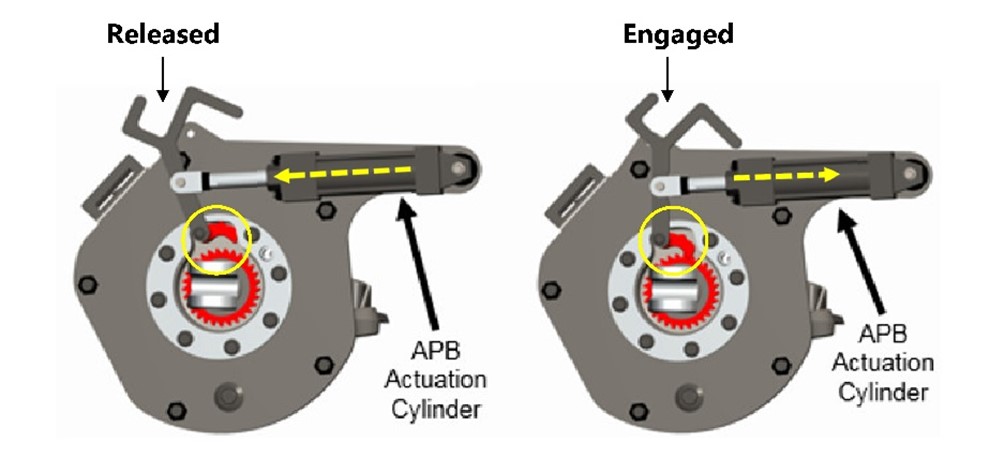
Automatic parking brakes can be configured for use on both truck-mounted and body-mounted brake systems, and they can be retrofitted on existing freight cars with no need to make modifications to the air brake system.
Figure 40 shows NYAB’s ParkLoc brake cylinder configured for use on a truck-mounted brake system on Wabash National freight cars. Figure 41 shows the ParkLoc brake cylinder configured for use on a standard body-mounted brake system as a retrofit solution.
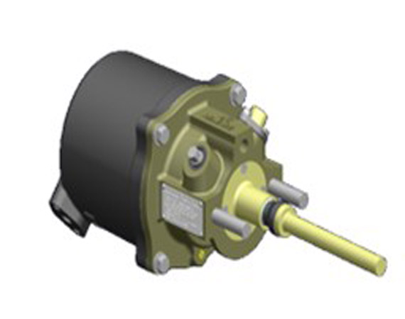
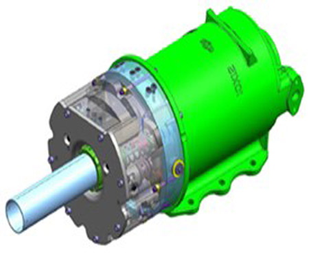
Wabtec’s APB is an integrated add-on to the non-pressure head of truck-mounted and body-mounted brake cylinders (Figure 42). The latching function is operated by a secondary mechanism that requires only 2½ cubic inches of air to activate. The APB can also be integrated with a body-mounted brake cylinder (Figure 43).

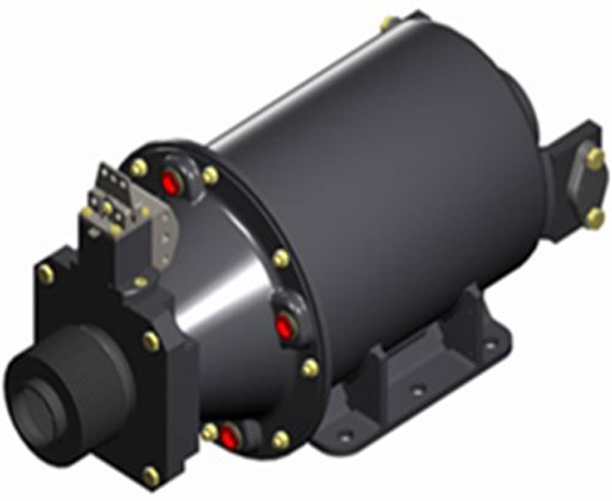
Wabtec also manufactures a pneumatic control module for the APB (Figure 44). The pneumatic control is a manifold connected to the APB, brake pipe, and auxiliary reservoir on each car for manual control of the automatic air brake.
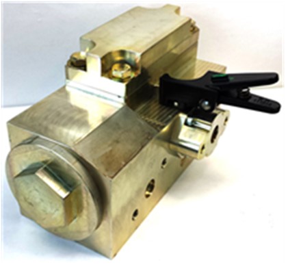
In this design, a ball valve can be manually closed on each car to isolate the APB from the brake pipe, thereby maintaining the parking brake in the applied state while the brake pipe is recharging. It has a similar function as retainers on traditional hand brakes, with some notable exceptions:
- The pneumatic control module retains the full brake force, contrary to traditional retainers which retain only 20 psi of brake pipe pressure when set to the HP position.
- These modules also do not release the brake force even when the BCP becomes depleted due to leaks.
1.23.2 Brake cylinder maintaining feature
The QSLV on all AAR-approved CCVs is equipped with a pressure maintaining feature. This feature ensures that the pressure in the brake cylinder remains between 8 and 12 psi, even when brake cylinder leakage exists. The QSLV replenishes any air that leaks from the brake cylinder by diverting brake pipe air into the brake cylinder. This feature, however, is effective only as long as air pressure exists in the brake pipe; it is not available during an emergency brake application, because applying the brakes in emergency depletes the brake pipe pressure completely.
Since 2014, CCVs have included a brake cylinder maintaining (BCM) feature in addition to the QSLV pressure maintaining feature. BCM is available not only for minimum brake applications, but also up to a full-service brake application.Footnote 97 The extended operating range of BCM offsets air leakage from the brake cylinder by diverting brake pipe air into the brake cylinder to maintain it at the targeted BCP levels in response to automatic brake applications.
According to AAR Standard S-486, the maximum acceptable limit of brake cylinder leakage during an SCT is 1 psi/minute. Footnote 98 Figure 45 illustrates BCM activation at this leakage rate for an automatic brake application of 15 psi brake pipe reduction. It shows that, without BCM, the initial BCP of 37 psi will leak down to the 8 to 12 psi maintained by the QSLV after 20 minutes (1200 seconds) of a sustained brake application on a long descending grade. The BCM feature will restore the pressure leaked off from the brake cylinder to its target level of 37 psi by using brake pipe air to offset the leakage.
![Activation of brake cylinder maintaining feature for a 1 psi/minute leakage rate of brake cylinder pressure (Source: A. Aronian & L. Vaughn, “NYAB Brake Cylinder Maintaining and Field Trials Update”, presented at the Air Brake Association Conference, Minneapolis, Minnesota [October 2015])](./images/r19c0015-figure-45.jpg)
By maintaining the target BCP to compensate brake cylinder air pressure loss due to leakage, BCM improves the overall brake efficiency of the train’s automatic brakes in extreme cold temperature. Improved brake efficiency, in turn, will improve train handling and maintain a uniform brake application to balance the train’s speed on descending grades, even when cars have brake cylinder leakage. Field testing has proved that brake cylinder leakage of up to 2 psi/minute (double the maximum acceptable limit stated in AAR Standard S-486) can be mitigated by the BCM feature.
1.23.3 Dynamic brake retention on distributed power remote locomotives
DB holding is a feature that allows the DB on a locomotive to continue working in the event of an emergency brake application.
On territories where locomotives with DB are required, these locomotives must have the DB holding feature. TC’s Railway Locomotive Inspection and Safety Rules, Part III: Locomotive Inspection Requirements sets forth the requirements for locomotive DB functionality. Section 21 (Brake System) states, in part,
21.2 A railway company shall file with the Department all territories on which locomotives with dynamic brake are required, as well as related instructions. This information shall be filed with the Department no later than ninety days from the approval of these rules.
[…]
21.4 All existing freight locomotives intended to operate in territory as set out in subsection 21.2 shall be modified prior to December 31, 2010 to incorporate a dynamic brake holding feature if not already equipped.
21.5(a) Dynamic brake is considered a supplemental braking system however company instructions and procedures shall ensure that the friction brakes are sufficient by themselves, without the aid of dynamic brakes, to stop the train safely under all operating conditions.Footnote 99
In addition, the AAR Specification S-5018 “Dynamic Brake Control” contains the following requirements with respect to DB brake holding in the context of emergency brake applications:
3.4 Locomotives with dynamic braking must be equipped with a dynamic brake-holding feature that operates in the following manner:
3.4.1 Maintains dynamic braking during a penalty or an emergency air brake application.Footnote 100
The above requirements are considered to have been met when locomotives in the head-end locomotive consist, not subject to restrictions on the number of braking axles, have DB holding. There is no requirement for DB holding on mid-train or tail-end remote locomotives.
On older DP systems, DB holding is not available on remotely controlled locomotives that are connected to the lead locomotive via radio communication DP protocol. However, GE-Wabtec, the manufacturer of DP systems, has developed a DB retention feature, similar to the DB holding feature on lead locomotives, that retains full DB capability when the remote locomotives go into emergency. This feature provides added safety for high-tonnage trains following emergency brake applications made when descending heavy and mountain grade territories.
The DB retention feature was not available on the 2 DP remote locomotives on the occurrence train, UP 5359 and CEFX 1040. Consequently, after the train was stopped in emergency at Partridge, the DB system on these locomotives was disabled. In lieu of DB holding, the DP system applied up to 45 psi of independent BCP when the emergency brakes were applied on the remote locomotives. This is a design characteristic of DP systems, intended to avoid thermal mechanical damage to the locomotive wheels when bringing the locomotives to a stop in emergency. Full independent BCP (72 psi) is used only when the locomotive is stationary.
1.23.4 Electronically controlled pneumatic brake system
Since the inception of the air brake system in the 1870s, the brake technology on freight trains has improved in performance and design, but the basic principle has remained the same: the application and release of the train’s air brakes is achieved through reductions and increases in the brake pipe pressure.
In the early 1990s, the AAR began looking into newer, more advanced brake technology, including the electronically controlled pneumatic (ECP) brake system.
On a train equipped with ECP, a brake controller is installed on the locomotive, and a car control device (CCD) is installed on each car. The brake controller interprets the brake application and release commands that it receives from the locomotive’s automatic brake handle and then sends an electronic wireline signal to the CCD on each car through an intra-car cable that runs the length of the train.
On the cars, the CCD interprets the signals and activates the CCV, thereby allowing air from the reservoir to travel into the brake cylinders, which provides the braking force. On an ECP system, the brake pipe’s sole purpose is to supply air to the reservoirs on the cars; it remains in a continuously charging state. This is different from the role of the brake pipe in standard pneumatic brake systems, in which reductions in brake pipe pressure are used to apply the brakes by activating each car’s CCV.Footnote 101
ECP systems offer several advantages over standard pneumatic brake technology, including the following:
- Near-instantaneous transmission of brake application and release commands through the use of wireline electronic signals.
- Remote monitoring of the brakes on each car from the locomotive cab. At any given time, the locomotive operator can view the status of each individual car and its braking performance on the operator display screen.
- Automatic car cut-out: the system automatically senses cars that are not responding as expected to the braking commands and cuts them out.
- Automatic penalty brake application: when the ECP system detects that 15% or more of the cars on the train have ineffective brakes, it automatically makes a penalty brake application, which brings the train to a full stop. When this occurs, the brakes can be recovered only by setting off the bad order cars.Footnote 102
- Graduated brake release. This feature allows the LE to reduce brake retardation effort without fully releasing the brakes and re-applying them (release and catch); this facilitates the task of properly balancing train speed during a continuous service brake application or when recovering from an emergency brake application.
- Constant replenishing of the brake pipe and car reservoirs.
- Continuous brake cylinder pressure control, which is the same as the BCM feature on cars not equipped with ECP.
ECP systems were nearly made mandatory by the U.S. Federal Railroad Administration in 2015. These systems would have been required on all unit trains carrying dangerous goods. However, this initiative was dropped in 2018 due to high initial implementation costs and logistics issues regarding the interoperability of trains that have ECP systems with trains that have pneumatic conventional brakes.
However, runaway trains are still occurring, sometimes with fatal consequences. In addition to this occurrence, 5 other significant runaway train events have occurred in North America between 2017 and 2019 that would have been preventable with ECP.
In Canada:
- On 10 January 2018, Canadian National Railway Company freight train L76951-10, proceeding southward on the Luscar Industrial Spur, leaked compressed air from the air brake system in extreme cold temperature conditions and started to roll uncontrolled while descending the mountain grade to Leyland, Alberta. The train reached a maximum speed of 53 mph before it came to a stop at Mile 0.5.Footnote 103
In the U.S.:
- In 2019, BNSF Railway trains in North Dakota ran away on 2 separate occasions (Dengate and Hettinger). In those occurrences, the cars were not able to propagate an emergency brake application after a pull-apart, which resulted in an uncontrolled movement.
- On 04 October 2018, a Union Pacific train with a pinched air hose ran away in Granite Canyon, Wyoming; it descended a steep grade uncontrolled at 50 mph before colliding into the back of a stationary train, resulting in 2 fatalities.
- On 02 August 2017, a 178-car CSX train ran away uncontrolled near Hyndman, Pennsylvania due to an undesired release of the brakes. After the train was brought to a stop and the emergency brake application was recovered, the train proceeded but subsequently derailed and released dangerous goods which caught fire.
1.23.5 High-capacity fade-resistant brake shoes
When the automatic brake is applied, heat is generated at the brake shoe/wheel tread interface. The amount of heat generated is proportional to BHP. Heavier cars need a higher retarding force for speed control when descending grades and therefore generate higher temperatures and are exposed to higher BHP.
When the thermal capacity of brake shoes is exceeded for a sufficient length of time, or when the speed of the train is increasing at a high rate, friction fade can occur and reduce the coefficient of friction. For a train to descend a long mountain grade at constant speed, any reduction in brake retarding force at those wheels where brake shoe friction fade is occurring must be compensated for by increasing the braking effort. The application of more brake shoe force can cause the wheels to be subject to even more friction fade due to the additional braking effort imposed upon them. This cycle of friction fade and higher brake force inputs will result in a spiralling condition of overall degradation of the retarding force available to control the train speed.
AAR Specification M-926, first issued in 1964, is the standard used to manufacture high-friction composition brake shoes for rail cars. The grade test specified in M-926 requires brake shoes to be exposed to a 1450-pound net shoe force (equivalent to a BCP of 22 psi) at 20 mph for 45 minutes and produce a minimum retarding force of 400 pounds. Although a BHP value is not specified in this specification, the retarding force is equivalent to a coefficient of friction of no less than 0.28 and BHP of 21 at a temperature of 600 °F (316 °C).
Following 2 catastrophic runaway derailments in the United States in 1997 and 2000, a Brake Shoe Fade Task ForceFootnote 104 was established to develop an appropriate grade test to address the higher shoe forces present on today’s heavier cars. The task force proposed a heavy grade test where the net shoe force input was increased well beyond the level indicated in AAR Specification M-926. Fade-resistant brake shoes with improved performance were designed to the proposed specification. This led in 2008 to a new AAR Specification, M-997 (Brake Shoe - High Friction Tread Conditioning, High Capacity). It specifies a new heavy grade test requirement, which requires that rail car brake shoes retain a minimum of 600-pound retarding force when exposed to a 2250-pound brake shoe force (equivalent to 34 psi BCP) for 45 minutes at a speed of 20 mph. The retarding force is also equivalent to a minimum coefficient of friction of 0.27, but for a much higher brake force input.
Since 2008, 2 brake shoe manufacturers in North America have offered this type of high-capacity, fade-resistant brake shoe: Railway Friction Products (a subsidiary of Wabtec) and Anchor Brake Shoe Company LLC (a subsidiary of NYAB). These brake shoes are known today as Cobra TreadGuard (RFP-Wabtec) and WheelSaver (Anchor-NYAB).
The AAR has not mandated the use of high-capacity fade-resistant brake shoes on all 110-ton heavy axle load freight cars, but requires that they be replaced in kind when a freight car is so equipped.Footnote 105 North American railways have slowlyFootnote 106 adopted these high-capacity brake shoes, partly because they cost more than the M-926 standard brake shoe. Other considerations include commodities being transported, territory of operation, and equipment utilization. Nevertheless, car owners and railways that operate in mountain grade territory can benefit from these fade-resistant brake shoes for their unit train operations because they add another level of safety.
The TSB has previously discussed the use and benefits of fade-resistant brake shoes in its investigation report following an occurrence on 29 June 2006 in which a CN freight train locomotive and a loaded car of lumber derailed after losing control while descending the grade near Lillooet, BC.Footnote 107 In that investigation, it was noted that an AAR Standard for fade-resistant brake shoes had been established and fade-resistant brake shoes had been developed, but their use had not been made mandatory. Therefore, the Board was concerned that heavier cars would continue to be operated with the older specification brake shoe. The AAR has not yet adopted a framework providing for the mandatory use of high-capacity brake shoes for equipment in interchange service.1.24 Training
1.24.1 Requirements and regulations
1.24.1.1 Railway Employee Qualification Standards Regulations
In Canada, federally regulated railways must abide by the Railway Employee Qualification Standards Regulations (the EQS Regulations). These regulations, which came into force in 1987, establish the minimum qualifications for LEs, transfer hostlers, conductors, and yard foremen. They apply to all railway employees performing the duties of the specified occupational category.
The training and qualification issue was examined by the 2017 Railway Safety Act (RSA) review panel. Its report, entitled Enhancing Rail Safety in Canada: Working Together for Safer Communities, included the following observations:
Although Transport Canada certifies aviation and marine crew members, there are no provisions for certifying railway employees or approving railway training programs. As such, each company is awarded considerable latitude in preparing and providing training and certification tailored to the specific needs of its employees. The Review heard from some Transport Canada inspectors that they occasionally note gaps in the consistency of training (e.g., knowledge) of railway personnel, and while CN and CP have taken steps to address training gaps through company training centres in Winnipeg and Calgary, further efforts could be made to strengthen training requirements of railway personnel. […]Footnote 108
The EQS Regulations require railways to file with TC a description of all employee training programs and subsequent changes related to each occupational category. Railways are also required to submit an updated report to TC on their employee training programs each year.
The training curriculum required for conductors and LEs includes the following:
- Regulations No. 0-8, Uniform Code of Operating Rules
- railway radio regulations
- dangerous commodities
- train marshalling
- air brake systems and tests
- freight car and train inspections
- passenger evacuation procedures
For LEs, additional required training includes locomotive operation, air brake and train handling.
Although the EQS Regulations require railway companies to file with TC information on their employee qualification program and any changes made to the program, the filings can be in the form of a summary and do not necessarily include all course content. While TC may occasionally conduct a cursory review of company submissions, the regulations do not require TC to review the course content in detail or to approve it.
1.24.1.2 Railway Safety Management System Regulations, 2015 and Railway Rules Governing Safety Critical Positions
Regulatory requirements for the training and certification of railway operating employees are specified in the Railway Safety Management System Regulations, 2015 (the SMS Regulations). Sections 25 to 27 of the SMS Regulations require a railway company to have a process for managing knowledge:
A railway company must establish a list setting out
- the duties that are essential to safe railway operations;
- the positions in the railway company that have responsibility for the performance of each of those duties; and
- the skills and qualifications required to perform each of those duties safely.Footnote 109
The SMS Regulations also require that railway companies include the following in their SMS:
- a plan for ensuring that an employee who performs any of the duties referred to in the list has the skills, knowledge and qualifications required to perform their duties safely
- a method for verifying that an employee who performs any of the duties referred to in the list has the skills, knowledge and qualifications required to perform their duties safely
- a method for verifying that a supervisor who performs any of the duties referred to in the list has the skills, knowledge and qualifications required to perform their duties safely
The TC-approved Railway Rules Governing Safety Critical Positions were developed pursuant to section 20 of the RSA. Section 3 of those rules states the following:
A “Safety Critical Position” is herein defined as:
1. any railway position directly engaged in operation of trains in main track or yard service; and
2. any railway position engaged in rail traffic control.
Any person performing any of the duties normally performed by a person holding a Safety Critical Position, as set out in section 3 above, is deemed to be holding a Safety Critical Position while performing those duties.Footnote 110
1.24.2 Canadian Pacific training program
1.24.2.1 Training for conductors
CP’s training program for new conductors consists of classroom training and on-the-job training; the classroom portion includes:
- 2 weeks of initial classroom training (general orientation and basic safety instructions);
- a critical task sign-off prior to field training (assessment conducted in the field to confirm that the trainee is physically able to perform critical tasks);
- 4 weeks of on-the-job training, including yard and road trips with a coach;
- 2 weeks of additional classroom training, where trainees receive comprehensive rules and instructions training on various subjects, including safe work procedures, CROR, company GOIs, and special instructions; and
- 2 weeks in a simulated environment where trainees practice applying rules and GOIs as well as crew resource management (CRM) principles.
Following the classroom training, conductor trainees begin the practical portion of the training program. During on-the-job training, qualified conductors coach and mentor the trainees on the rules and instructions pertaining to the work, and on the specifics of the yard or territory. The trainees then put into practice what they learn in the classroom. On average, trainees complete on-the-job training to proficiency over a 5-month period and become qualified once a company manager, who observes them in the field, deems them ready.
1.24.2.2 Training for locomotive engineers
Qualified unionized conductors can apply after a 2-year period to become an LE by taking the following additional training:
- 4 weeks of classroom training, including one week of a detailed review of CROR, safety, and general rules.
- On-the-job training, during which the trainees complete a number of training trips on various subdivisions with a supervising LE until they are proficient at train handling. These trips also help to familiarize the trainees with the subdivisions within their territory.
- 2 weeks of mechanical classroom training, including troubleshooting, air brake systems, train handling instructions, fuel conservation, track/train dynamics, and DP.
After 3 months of combined classroom and on-the-job training, employees are recalled for a final examination. They then resume on-the-job training until they qualify.
1.24.2.3 Supervisor qualification and training
Trainmasters, as first-line supervisors, assume the general supervision of LEs and conductors and oversee the day-to-day train operations on their assigned territory. Trainmasters usually come from a qualified railway position (often related to train operations), but it is increasingly common for candidates to be hired from outside the railway industry. They receive extensive training in railway operations, including conductor and LE certifications.
Many railway companies in North America, including CP, also employ road foremen. This is also a supervisory role, but with a focus on the technical aspects of train operations (train handling, air brake operation, train dynamics). Road foremen are experienced LEs with high technical and operational expertise. They are responsible for training, coaching, and evaluating the performance of LEs and conductors. They intervene in complex operational situations, such as emergency brake recovery on a mountain grade, to share their experience and knowledge and provide solutions.
The position of road foreman for the Calgary terminal was vacant from 2016 to 2018. The road foreman duties were transferred to the trainmasters; however, no special training was provided to bridge the technical gap and the difference in experience that existed between the 2 positions.
At the time of the occurrence, there was 1 person holding the title of road foreman at the Calgary terminal, but the incumbent ’s technical expertise and experience were similar to those of a trainmaster.
1.24.2.4 Field Hill training and certification
After 2 occurrences on Field Hill—one in 1997 which resulted in an uncontrolled high-speed descent and the derailment of 66 carsFootnote 111 and one in January 1998 in which a freight train handling 112 cars ran uncontrolled between the Upper Spiral Tunnel and FieldFootnote 112 —CP made modifications to the FHOP. CP later initiated changes to its training program for both conductors and LEs working on the Laggan Subdivision.
1.24.2.4.1 Field Hill certification for conductors
Operating in mountain grade territory can significantly alter the complexity of a conductor’s duties, introducing additional cognitive demands.Footnote 113
After the accident in 1997, CP developed a training program for conductors operating on Field Hill entitled Canadian Pacific Railway Calgary Terminal Field Hill Simulator Training. The program put an emphasis on mountain and heavy grade operations and included the following activities:
- the review of the FHOP, including requirements of CROR, GOI, and application of retainers and hand brakes;
- the review of emergency, recovery, and undesired release scenarios;
- 5 trips down Field Hill with a qualified conductor;
- participation in 5 simulation trips accompanied by a field placement coordinator, with evaluations signed by both the trainee and the coordinator after each trip;
- a test to ensure conductors understood required procedures; and
- a final trip down Field Hill with a placement coordinator who assesses whether qualification was met.
The duration of the training was approximately 2 months longer than the standard conductor training, and conductors who completed it successfully received a Field Hill certification.
The training program was significantly modified in 2017–2018; it was accelerated, as there was a greater demand for conductors due to increased traffic levels. The new requirements for a conductor to work on Field Hill, up to the time of the occurrence, were reduced to classroom review of the FHOP using job aids and track schematics. The simulation trips on Field Hill were removed. Conductors were no longer required to be Field Hill–certified.
1.24.2.4.2 Field Hill certification for locomotive engineers
LEs must be certified for the subdivision on which they operate. On the Laggan Subdivision, the certification for LEs requires approximately 3 extra months of training specifically dedicated to Field Hill operations. The training also includes 3 to 4 days with a trainmaster to practise and qualify in the following skills:
- ascending and descending the mountain grade of Field Hill
- performing “stop and go” scenarios at Partridge and full service “release and catch” at Cathedral, while maintaining proper control of the train
A checklist specific to Field Hill was developed in 1998 to be used in conjunction with the Locomotive Engineer Evaluation Form to reflect special requirements when evaluating the performance of LEs on Field Hill. These forms facilitate evaluation of LE proficiency in the use of air brakes and DBs, and are to be completed by a supervisor. After the compulsory trips are completed successfully, the trainmaster qualifies the LE, and the LE’s training record includes the “Field Hill–certified” designation. This training and certification were still in effect at the time of the occurrence.
1.24.2.5 Training and experience of the inbound crew and trainmaster
1.24.2.5.1 Conductor
The conductor on the inbound crew qualified after 5 months of training. During the on-the-job training period, she performed mostly yard service shifts accompanied by a qualified conductor. In addition, she took 3 trips on Field Hill and had practised approximately 8 simulator trips, but none on Field Hill. During the classroom training, the FHOP and the use of retainers were discussed but the need to observe piston position was not included, nor was the setting of retainers reinforced by in-the-field practice.
On the day of the occurrence, the conductor and the LE discussed retainers and practised setting them while waiting in a siding at Keith. The conductor’s training and experience did not lead to an awareness for the need to observe piston position while setting retainers, which would have provided an indication of which brake cylinder pistons were fully retracted and would not provide the desired brake force.Footnote 114
1.24.2.5.2 Locomotive engineer
The LE on the inbound crew was hired in November 2005 and initially qualified as a conductor in May 2006. He started his LE training in January 2012 and qualified in August 2012. During his on-the-job training, he was taking 2 to 3 trips a week, coached by senior LEs. He had followed the program specifically designed for Field Hill operations and was Field Hill–certified.
1.24.2.5.3 Trainmaster
The trainmaster joined CP in 2008 as an RTC where he gained some preliminary experience dispatching the Laggan Subdivision during his first year of service. He qualified as a conductor in 2013 and as an LE in 2015. He became trainmaster in January 2016, after taking the managers’ training programs. He was not Field Hill–certified. At the time of the occurrence, he had taken over 100 trips as an LE, most of them on mountainous territory on the Cranbrook and Windermere subdivisions, and had worked on the Laggan Subdivision as a conductor.
1.25 Coaching assessments and proficiency testing
CP regularly conducts coaching assessments (pre-qualification evaluations and field placement trips) on trainees and proficiency testing (efficiency tests and ride-along trips) on qualified crew members to evaluate their skills in train operation and adherence to rules and procedures.
The investigation reviewed the results of the assessments and tests conducted for the members of the inbound crew.
1.25.1 Coaching assessments
Coaching assessments are performed as part of the training program, to evaluate the performance of trainees before they qualify for their respective positions.
1.25.1.1 Inbound locomotive engineer
Coaching assessments for the LE on the inbound crew were completed 12 times during his training in 2012. Of these assessments, 9 were pre-qualification evaluations and 3 were field placement trips. All were on the Laggan Subdivision.
After each pre-qualification evaluation, the accompanying evaluation officer (trainmaster or road foreman) completed a report that indicated the name of the officer and the LE trainee, the date, and the trip location. The report also provided a checklist of operational tasks covered in the evaluation, such as terminal preparation, switching en route, descending a heavy or mountain grade, and CRM.
A report was also completed by the LE instructor after each field placement trip. In these reports, the LE’s performance for each evaluated operational task was rated from 1 to 4. A rating of 1 meant “needs improvement,” a rating of 2 meant “developing,” a rating of 3 meant “achieved standard,” and a rating of 4 meant the task was not performed. The LE’s performance for these tasks received an equal number of 2 and 3 ratings.
All reports for the pre-qualification evaluations and the field placement trips also contained constructive comments and indicated that the LE’s performance on the evaluated tasks was satisfactory.
1.25.1.2 Inbound conductor
Pre-qualification evaluations for the conductor on the inbound crew were completed 26 times during her training in 2018. Out of the 26 evaluations, 3 took place while on trains operating westward on the Laggan Subdivision; the others took place either in yards or on the Red Deer Subdivision. Pre-qualification evaluations are not required to be conducted on a particular subdivision.
After each pre-qualification evaluation, the trainer completed a report which indicated the name of the trainer and the conductor trainee, the date, and the train number. The report also provided a checklist of operational tasks covered in the evaluation. For each operational task, the conductor trainee’s performance was rated from 1 to 4. Eighty percent of the time, the conductor trainee’s performance was rated as a 2. The evaluation form also included a comment section, which was filled out 42 percent of the time. None of the tasks rated or comments provided were related to conditions relevant to this occurrence.
1.25.2 Proficiency tests
There are 2 main methods of conducting proficiency tests for qualified crew members:
- efficiency tests, in which crew members are observed, usually from the ground, to assess their on-the-job performance and their adherence to regulations and safe work practices, and
- ride-along trips, in which a supervisor observes crew members while riding in the locomotive cab.
As part of proficiency testing, supervisors may also review event recorder downloads, monitor radio communications, and take radar speed measurements.
Supervisors conduct proficiency tests at random, except in situations where an employee is known to require more attention. For this reason, the number of tests that an employee receives can vary from year to year, and some employees could be tested significantly more often than others, if they happen to be on duty when the trainmaster is conducting tests.
1.25.2.1 Efficiency tests
CP’s 2019 T&E Manager Safety Accountabilities document specifies that each trainmaster must conduct 10 efficiency tests per week, or 40 per month. Footnote 115 The document does not specify the number of efficiency tests to be taken for each supervised employee.
The results of the efficiency tests for the inbound crew are shown in tables 19 and 20. The investigation determined that failed tests were not assessing operational tasks relevant to the occurrence.
| Year | Number of tests taken | Number of tests passed | Number of tests failed |
|---|---|---|---|
| 2012 | 3 | 3 | 0 |
| 2013 | 40 | 31 | 9 |
| 2014 | 45 | 45 | 0 |
| 2015 | 34 | 31 | 3 |
| 2016 | 36 | 35 | 1 |
| 2017 | 29 | 27 | 2 |
| 2018 | 15 | 15 | 0 |
| Year | Number of tests taken | Number of tests passed | Number of tests failed |
|---|---|---|---|
| 2018 | 30 | 28 | 2 |
| 2019 | 2 | 2 | 0 |
1.25.2.2 Ride-along trips
At CP, all active train and engine employees on the territory are expected to be accompanied by a supervisor for a train ride-along at least once every 12 months.
CP’s 2019 T&E Manager Safety Accountabilities document, which was in effect at the time of the occurrence, specifies that trainmasters are required to ride with LEs and conductors to ensure crew proficiency and compliance 2 times per week or 8 times per month. Footnote 116
The results of ride-along trips are recorded on trip evaluation reports. These reports include date, time, names of employee and officer, and test code. The performance of the employee is indicated as a simple pass or fail, based on a subjective assessment by the trainmaster; there are no additional comments that could indicate areas in which the employee’s performance was especially commendable, or identify weaknesses and promote corrective measures.
From the time he qualified in 2012 to the day of the occurrence, the LE on the inbound crew was accompanied by a supervisor on 39 ride-along trips (Table 21).
| Year | Number of trips |
|---|---|
| 2013 | 8 |
| 2014 | 11 |
| 2015 | 4 |
| 2016 | 5 |
| 2017 | 5 |
| 2018 | 6 |
From the time she qualified in 2018 to the day of the occurrence, the conductor on the inbound crew was accompanied by a supervisor on 9 ride-along trips.
The TSB requested the results of these trips, but CP was unable to provide them; the documentation stated that the results were “unknown.”
1.26 Best practices in developing competence
The Rail Safety and Standards Board in the United Kingdom published a guidance document entitled Good Practice Guide on Competence Development.Footnote 117 The guide, developed in consultation with the railway industry, was intended to provide best practices for developing comprehensive systems to manage competence rather than simply ensuring compliance with regulations.
“Competence” refers to the overall ability to function effectively in a position and results from the combination of functional, technical, and non-technical skills. According to the guide, non-technical skills include situational awareness, decision making, and workload management, which have been shown to play a key role in incidents and accidents.
The Office of Rail Regulation in the United Kingdom published a guide entitled Developing and Maintaining Staff Competence. The guide recognizes that training programs should be sufficient to prepare individuals to handle expected operations and that experience, obtained under supervision, allows individuals to carry out progressively more complex tasks.
Training and development seek to create a level of competence for the individual or team, sufficient to allow individuals or teams to undertake the operation at a basic level. Initially, this will be under direct supervision, which will become less direct. Over time, as knowledge and practical experience grow, operations can be carried out at a more complex level.Footnote 118
The guide recognizes that competence development is an important contributor to managing risks, specifying that the first step in developing a competence management system is to identify activities that affect operational safety and that are critical for controlling risk. This makes it possible to identify a combination of risk control measures and to take actions to develop competence where it is required to manage risks.
1.27 Previous recommendation concerning employee qualifications
The 17 June 2016 occurrence at the Canadian National Railway Company MacMillan Yard in Vaughan, Ontario, involving an uncontrolled movement during remote control locomotive system operations, highlighted deficiencies in the EQS Regulations.Footnote 119 Following the TSB investigation into this occurrence, the Board recommended that
the Department of Transport update the Railway Employee Qualification Standards Regulations to address the existing gaps for railway employees in safety-critical positions related to training, qualification and re-qualification standards, and regulatory oversight.
TSB Recommendation R18-02
In its January 2021 response to this recommendation, TC said that it was in the process of identifying amendments to the EQS Regulations, and that stakeholder consultations on the proposed amendments would be launched by March 2021. In March 2021, the Board assessed TC’s response to Recommendation R18-02 as having Satisfactory Intent.Footnote 120
1.28 Crew resource management
CRM is a method of making effective use of available resources (human, hardware, and information) to mitigate emergent threats, such as abnormal equipment function or lapses in human performance, by putting into practice technical proficiency, teamwork, situational awareness, communication, and personal assertiveness.
CRM focuses on providing crews with the interpersonal skills required to carry out their tasks safely: “CRM training typically consists of an ongoing training and monitoring process through which personnel are trained to approach their activities from a team perspective rather than from an individual perspective.”Footnote 121
Since 1998, the TSB has investigated 5 main-track train collisions in which the effectiveness of CRM practices was considered (Appendix H).
1.28.1 Crew resource management training in the rail industry
Significant safety benefits have been accrued in the aviation and marine industries with the introduction of CRM. Given the prevalence of human factors in rail accident statistics, CRM training could yield significant safety benefits in the rail industry as well.Footnote 122
CRM training is aimed at reducing human factors-related accidents. For example, it can provide crews with strategies to improve communication and interactions in order to align mental models,Footnote 123 increase situational awareness, and counter the effects of limited resources available to problem solvers who are closest to the situation.
Following a 1998 collision between 2 freight trains, the U.S. National Transportation Safety Board recommended that a number of railway stakeholders, including the regulator, operators, industry associations, and labour organizations, collaborate to develop and require CRM training in the railway industry. That training would cover, at a minimum, crew member proficiency; situational awareness; effective communication and teamwork; and strategies for challenging and questioning authority in an appropriate manner.Footnote 124
Subsequent to this recommendation, the U.S. Federal Railroad Administration, in cooperation with academic and industry partners, developed and piloted rail CRM training.Footnote 125 Initial assessment of the pilot training showed increases in knowledge and improved attitudes toward CRM principles.Footnote 126
However, this type of training is not mandatory in either Canada or the U.S. A review of the adaptation of CRM principles outside of aviation in 2010 found that, in the North American railway industry, “interest in CRM training principles remains sporadic.”Footnote 127 The review also described voluntary initiatives by specific railways to implement CRM training, as well as industry initiatives to develop training materials for operators to use. For example, the review indicated that CP implemented a CRM training program targeted at new-hire conductors and trainmen in 1999.
1.28.1.1 Crew resource management training at Canadian Pacific
CP was one of the early adopters in the railway industry of CRM training. Since 1999, employees assigned to operational roles have undergone mandatory training in CRM, either online or via an instructor-led course. The training consists of a 1-hour presentation during the first week of the classroom portion of the conductor program and is 1 of 11 modules presented on the same day. CP’s 6-weeks training for new hires puts a special emphasis on CRM, and its principles and techniques are practised through simulations over a 2-week period. CP does not provide recurrent CRM training to its operating employees when they requalify. From CP’s perspective, since CRM principles are used daily in operations, the subject does not require recurrent training.
As stated in the most recent version of the CP CRM training module, the material was developed to “…pull together all the resources available to create a process that supports appropriate changes in the application of rules, training, and operating practices.”Footnote 128 The CRM training is divided into the following fundamental areas:
- human factors
- situational awareness
- technical proficiency
- communication
- teamwork
1.28.1 Applied crew resource management
At CP’s operational level, the core of CRM is expected to be practised during job briefings, in which individuals discuss operational issues and work plans.
1.28.2.1 Crew resource management and communications
One of the core principles of CRM is effective communication among team members. Checklists standardize team communications by giving crew members an objective framework that provides:
- a standard foundation for verifying vehicle configuration that will attempt to counteract any reduction in the crew's psychological and physical condition;
- a sequential framework to meet internal and external operational requirements;
- mutual supervision (cross-checking) among crew members;
- the ability to dictate the duties of each crew member in order to facilitate optimum crew coordination as well as logical distribution of workload;
- an enhanced team concept by keeping all crew members in the loop; and
- a quality control tool by management and regulators over the crews.
Operator checklists are widespread across transportation domains, notably in air and marine modes.Footnote 129 However, checklists are not generally used in railway operations.
1.28.2.2 Crew resource management and situational awareness
People working in operational environments make decisions by building a mental model of their operational environment. This mental model is supported by an individual’s situational awareness, which refers to “the perception of elements in the environment within a volume of time and space, the comprehension of their meaning, and the projection of their status in the near future.”Footnote 130 Situational awareness is a critical component of decision making and involves information-processing stages at which shortcomings may occur. These shortcomings may result in an incomplete or inadequate perception of the situation.
Accurate situational awareness represents a defence against operational hazards in complex organizations like railways. Appropriate situational awareness is based on access to the best available data that can be synthesized into useful information that front-line operators can use in decision making.
In addition to policies and regulations (e.g., mandatory event reporting), a robust CRM program acts as another potential defence against systemic hazards in complex organizations.
1.28.2.3 Crew resource management and decision making
Because they facilitate information sharing among team members, CRM strategies can help ensure that team interactions (i.e., communication and coordination) are effective in situations in which the command and decision-making power hierarchy is unclear or unbalanced among the team.
An authority gradientFootnote 131 is defined as an established or perceived distribution of power among members of a team. A steep gradient may result in a situation where decision making is centralized with a single individual, whose status, experience or decision-making style precludes consensus-based decision-making within the group.
In the railway hierarchy, a train crew will normally perceive the trainmaster as the authority. Conformity is often in response to a perceived authority, or in reaction to an authoritarian leader (steep gradient).
Good quality communication in the decision-making process is particularly important considering that the trainmaster’s participation is almost always remote. As such, the trainmaster’s role is “narrowly embedded” in the team, a situation in which, according to human factors research, the trainmaster depends heavily on “others for acquiring a basis for their decision making and may have little control over the authenticity or accuracy of the information provided.”Footnote 132
1.28.2.4 Crew resource management as mitigation to limited resources
In the context of the relationship between cognitive behaviour and human performance, human factors literature defines the concept of bounded rationality and its relationship to error.Footnote 133
People working in industries such as the railway industry use their knowledge and available resources to pursue their goals based on their view of the situation. Further, safety is created when people are able to successfully “pursue goals and match procedures to situations […] resolve conflicts, anticipate hazards, accommodate variation and change, cope with surprise, work around obstacles, close gaps between plans and real situations, detect and recover from miscommunications and mis-assessments.”Footnote 134
The bounded rationality phenomenon partly describes the mismatch between successful human performance and the limited resources available to people at the sharp end of operations (train crews), which may result in lapses or error. People's behaviour can be viewed as “rational,” though possibly erroneous, when seen from the point of view of their knowledge, their mindset, and the multiple goals they are trying to balance.Footnote 135
1.29 Safety management systems
A safety management system (SMS) is a formal framework for managing risk that helps companies manage the safety of their operations by requiring them to
- identify hazards, assess the level of risk they represent, and take steps to reduce those risks where required;
- build a safety culture in day-to-day operations at all levels of the company; and
- involve company employees by
- collaborating or consulting with them;
- informing them of risks and how the company has dealt with these risks; and
- developing a procedure for employees to report contraventions and safety hazards to the company, and a policy for protecting employees who report contraventions and safety hazards.
SMS was designed around evolving concepts about safety that are believed to offer greater potential for effective risk management. The traditional approach to regulatory oversight was based on inspections for compliance and enforcement activities. SMS, in contrast, seeks to ensure that organizations have processes in place to systematically manage risks. SMS has been progressively introduced in the Canadian transportation industry because, when combined with inspections and enforcement, it is more effective in reducing accident rates. SMS can improve safety effectiveness and efficiency because it
- promotes accountability and timely remedial actions in the management of safety, without TC prescribing one-size-fits-all requirements;
- enables companies to be more proactive by leveraging operational expertise to identify hazards, and assessing and reducing risks; and
- enables measures to be taken to reduce risks that may exceed regulatory standards.
SMS can enhance safety by companies managing safety risks before TC has to intervene, and before major safety issues emerge. SMS complements but does not replace the existing railway safety regulatory and oversight framework. Companies must continue to meet RSA requirements and associated regulations, rules and engineering standards.
1.29.1 Railway Safety Management Systems Regulations, 2015
In May 2013, the RSA was amended to enable improvements to the Railway Safety Management Systems Regulations and the implementation of regulations pertaining to administrative monetary penalties and railway operating certificates. The Railway Safety Management System Regulations, 2015 (the SMS Regulations) came into force on 01 April 2015.
Under the SMS Regulations, federally regulated railway companies must develop and implement an SMS, create an index of all required processes, keep records, notify the Minister of Transport of proposed changes to their operations, and file SMS documentation with the Minister when requested.
The new regulations contain increased prescriptive requirements that outline how to achieve a result, and management-based requirements, which require the railways to develop and implement systems or processes but allows for flexibility in determining the most appropriate way to implement them based on company-specific factors.
Risk management is an important component of the SMS Regulations. One aspect of risk management consists of conducting analyses of the railway operations to identify hazards and safety issues, emerging trends or recurring situations. As part of the analysis, if a trend or recurring situation identified a safety concern, a risk assessment had to be performed to determine which mitigation or control measures to implement. Section 5 of the SMS Regulations states, in part,
A railway company must develop and implement a safety management system that includes
[…]
(e) a process for identifying safety concerns;
(f) a risk assessment process;
[…]
(i) a process for reporting contraventions and safety hazards;
(j) a process for managing knowledge; […]Footnote 136
However, TC does not specifically define in the SMS Regulations what a safety concern is.
Section 13 of the SMS Regulations states, in part,
A railway company must, on a continual basis, conduct analyses of its railway operations to identify safety concerns, including any trends, any emerging trends or any repetitive [sic] situations. The analyses must, at a minimum, be based on
[…]
(e) any reports of contraventions or safety hazards that are received by the railway company from its employees;
(f) any complaints relating to safety that are received by the railway company;
(g) any data from safety monitoring technologies; […]Footnote 137
Section 15 of the SMS Regulations lists the circumstances in which railway companies must conduct a risk assessment.
A railway company must conduct a risk assessment in the following circumstances:
(a) when it identifies a safety concern in its railway operations as a result of the analyses conducted under section 13;
[…]
(c) when a proposed change to its railway operations, including a change set out below, may affect the safety of the public or personnel or the protection of property or the environment:
[…]
(v) a change affecting personnel, including an increase or decrease in the number of employees or a change in their responsibilities or duties.Footnote 138
1.29.2 Canadian Pacific’s safety management system
In accordance with the SMS Regulations, CP has developed and implemented a detailed SMS. CP’s SMS includes a hazard prevention program as well as a risk assessment policy and procedure, both of which are routinely updated and refined to support continuous improvement. With these 2 instruments, hazards can be reported, assessed, and mitigated.
1.29.2.1 Safety hazard reporting
As part of CP’s SMS, and in accordance with CP’s occupational health and safety requirements under the Canada Labour Code, train crews are required to file safety hazard reports when they experience or observe events that, in their experience, represent an unsafe circumstance that could lead to an accident.
CP’s Reporting Contraventions, Safety Hazards and Identifying Safety Concerns Procedure in effect at the time of the occurrence outlines the situations in which a safety hazard report should be made and an analysis conducted to identify safety concerns, emerging trends or recurring situations:
- reports of railway occurrences and pertinent supporting documentation;
- reports of contraventions and/or Safety Hazards from employees;
- results of audits/inspections conducted internally or by a Railway Safety Inspector; identifying safety concerns at CP;
- complaints relating to safety received by the Company;
- any data from safety monitoring technologies; and
- conclusions from the Annual Report prepared as per the requirements of H&S 5551 Safety Management System (SMS) Continual Monitoring procedure.Footnote 139
Hazard reports are submitted by employees on paper, or electronically using the Safety Hazard Reporting application.
Once a hazard has been reported, the procedure outlines the steps that should be taken to address the concern:
- The report is sent to the supervisor, who then must rate the severity of the issue, resolve the issue and provide a response back to the employee within 14 days.
- If not resolved, the safety hazard report goes to the workplace health and safety committee, who then has 30 days to resolve the issues and report back the results in writing to the employee.
- If the issue is still not resolved, there is a multi-stage escalation process that must be done in writing, beginning at the superintendent / director / assistant chief engineer level, and culminating at the Policy Committee. Each level has 30 days to respond.
- CP policy requires that all written records of the safety hazard reporting process be maintained for a period of 6 years.
1.29.2.1.1 Calgary Cross-Functional Health and Safety Committee
At the Calgary terminal, many safety hazards are addressed informally between staff and supervisors. In these cases, the incidents are not captured by the Safety Hazard Reporting application. When hazard reports submitted to a supervisor are not resolved within 14 days, they are forwarded to the Calgary Cross-Functional Health and Safety Committee (CCFHSC).
This committee has the authority to evaluate issues related to the Canada Labour Code, Part II and all associated occupational health and safety regulations for railways, CP’s SMS, and any health and safety provisions in the various collective agreements. The committee consists of
- 6 representatives from employee union groups (Unifor diesel shop, Unifor car department, Teamsters Canada Rail Conference (TCRC) yardmen, TCRC brakemen/conductor, TCRC engineer, and United Steelworkers crew bus/clerk); and
- 3 representatives from the employer (general superintendent, diesel manager, mechanical car manager)Footnote 140
1.29.2.1.2 Safety hazard reports of train handling issues on Field Hill
The investigation examined 3 years of the CCFHSC meeting minutes dating back to December 2016, focusing on the safety hazard reports and issues presented to the committee relating to train handling difficulties on Field Hill.
The meeting minutes showed that hazard reports were not always rated by a supervisor. In addition, some reports were closed out without any clear identification of the corrective action undertaken, or any indication of verification that the action had been completed or was effective.
The reported hazards discussed in the meeting minutes are summarized in Table 22.
| Meeting month and year | Summary of meeting minutes related to Field Hill |
|---|---|
| December 2016 | In the 14 December 2016 minutes, a new business item identified that train crews were reporting that they had to use full service, or nearly full service, braking to control speed in a manner consistent with speed restrictions. The minutes questioned whether cars were being properly maintained and/or if proper pre-departure brake tests were being conducted consistently between Alyth and Port Coquitlam yards. |
| January 2017 | The 07 January 2017 minutes mentioned a hazard report in which a grain train crew indicated having difficulty controlling the train speed on Field Hill. |
| March 2017 | The March 2017 minutes noted that the maintenance and/or pre-departure brake tests were not consistent between Alyth and Port Coquitlam yards. The action recommended for the reported train air brake issues was “better maintenance of the equipment.” |
| April 2017 | The December 2016 issue of having to use full service, or nearly full service, braking to control speed on Field Hill, and the January 2017 hazard report indicating a grain train crew having difficulty controlling speed, were listed as complete. There was no documentation to indicate what was done to list the items as complete. |
| January 2018 | New business items in the meeting minutes indicated that trains were going down Field Hill in full service during extreme cold temperatures. The minutes also indicated that the crews had been advised that it was fine to take trains down Field Hill with more than the allowable limit of flow.Footnote 141 |
| March 2018 | The issue identified in the January 2018 minutes related to braking on Field Hill in extreme cold was listed as complete. The documentation indicated that a bulletin would be issued by September 2018 to keep train speed under 10 mph when temperatures are colder than −25 °C. |
| March 2018 | The March 2018 minutes identified a new issue regarding multiple trains that were proceeding onto Field Hill without having received a No. 1 brake test on the full train consist. Five of the 10 trains identified in the minutes were westbound loaded grain trains. Records for these 5 trains showed that instead of a No. 1 brake test, a No. 1A brake test was done.Footnote 142 |
| April 2018 | Four (4) additional westbound loaded unit grain trains were reported to have received a No. 1A brake test instead of the No. 1 brake test. This information was added to the list of issues identified in March 2018. |
| May 2018 | The issue identified in March 2018 was updated to include additional information regarding train 301-294 that was reported to have only had a No. 1A brake test. This train had to be placed in emergency by the LE upon leaving Cathedral. The application of the emergency brakes had been necessary because all service brake functional capacity had been used and the train was still accelerating after reaching a speed of 19 mph. |
| June 2018 | The issue noted in March 2018 regarding the No. 1 brake test was listed as complete. As a recommended action, the minutes indicated that no train was to leave Alyth Yard without a No. 1 brake test, and that the RTC should be alerted to any trains arriving with only a No. 1A brake test. The minutes stated that the action was completed and that a bulletin would be issued; however, no due date was given for this action item. |
| August 2018 | A safety hazard report indicated that train 199-09 went into emergency on Field Hill. The recommended action was to make a troubleshooting document for trainmasters, which they could use to help crews who need assistance following the Field Hill procedures. |
| August 2018 | Train crews requested that the scanner at Mile 130.2 of the Laggan Subdivision be used for observing cars with air brakes not working. |
| September 2018 | The August 2018 action to provide a troubleshooting document that trainmasters could use to help crews who need assistance following the Field Hill procedures remained open. |
| September 2018 | The issue reported in August 2018 regarding the use of the scanner at Mile 130.2 for observing cars with air brakes not working was listed as complete however, the minutes did not indicate any action taken. |
| November 2018 | The Field Hill troubleshooting document for trainmasters identified as a recommended action in August 2018 was listed as complete. The meeting minutes did not indicate the action taken. However, CP determined that the development of a troubleshooting tree for trainmasters was not required and therefore none was developed. |
1.29.2.1.3 Safety hazard report on the day before the occurrence
In addition to the hazards listed in Table 22, on the day before the occurrence, the LE on the relief crew reported to the RTC that he had difficulties braking while coming down Field Hill on train 303-676, a loaded unit grain train. In fact, while descending the grade, the LE had been so close to a complete loss of control that he asked the RTC to clear the track ahead, including the tracks in Field. He had to fully apply the train brakes and use full locomotive DBs to maintain speed.Footnote 143 The LE completed a hazard report, in which he classified the hazard as “severe,” but he had not yet had an opportunity to file it; it was discovered in the wreckage at the occurrence site after the accident.
Wheel temperature data for this train taken at Mile 130.6 of the Laggan Subdivision indicated that 56% of the cars had ineffective brakes.Footnote 144 Upon arrival at Field, the train was identified during an inbound inspection as having a large number of cars with the brakes not applied.
1.29.2.2 Risk assessments
CP’s risk assessment procedure lists the conditions under which a risk assessment must be performed. It states, in part,
- A “Safety Concern” (i.e. a hazard or condition that may present a direct safety risk to employees, or pose a threat to safe railway operations) is identified through analysis of safety data;
- A proposed change to CP Operations that could:
- introduce a new hazard to the workplace resulting in adverse effects;
- negatively impact or contravene any existing policy, procedure, rule or work practice used to meet regulatory compliance or any CP requirements or standards;
- create or increase a direct safety risk to employees, railway property, property transported by the railway, the public or property adjacent to the railway; and
- require authority by a regulatory agency to implement.Footnote 145
If any one of the above listed criteria is identified, this triggers a risk assessment. The procedure outlines how to assess each identified safety concern or change to operations using the CP risk assessment tool. The process involves identifying all potential hazards associated with the scope of the risk assessment and then determining all the potential undesired events that could occur as a result of exposure to the identified hazards. A risk assessment is then performed on each undesired event.
Table 23 summarizes the number of risk assessments conducted by CP between 2015 and 2018 under the company SMS.
| Year | Total risk assessments | Risk assessment category | ||
|---|---|---|---|---|
| Safety concern | Proposed change | Others | ||
| 2015* | 9 | 0 | 9 | 0 |
| 2016 | 26 | 3 | 23 | 0 |
| 2017 | 7 | 0 | 7 | 0 |
| 2018 | 13 | 1 | 10 | 2 |
| Total | 55 | 4 | 49 | 2 |
* Significant revisions to the SMS Regulations came into force in 2015.
According to CP risk assessment records for the years 2015 to 2018:
- 47% of the risk assessments were conducted in 2016.
- 7% were conducted as a result of a safety concern derived from an analysis of safety data.
- 89% were conducted as a result of a proposed change to operations.
There was no record that any analysis or risk assessment had been done following the train crews’ filing safety hazard reports in which they were documenting their difficulties in controlling unit grain trains on Field Hill. Also, there were no indications that a risk assessment was used to validate the changes made to the FHOP between 1998 and 2015.
Since the new SMS Regulations came into effect in 2015, the TSB has investigated 6 other occurrences in which shortcomings in CP’s SMS were identified as a risk factor. In some, CP did not consider its operational changes to be significant enough to require a risk assessment; in others, it did not identify and mitigate all hazards (Appendix I).
1.29.2.3 Internal audit of the safety management system
Internal SMS audits play a critical role in the system’s continual improvement by providing the organization with an opportunity to assess the effectiveness of its safety management processes and to proactively take corrective measures.
Under sections 30, 31, and 32 of the SMS Regulations, a railway must conduct an audit of its SMS every 3 years and produce an action plan to address identified deficiencies.
In 2017, CP contracted Golder and Associates to audit its SMS. The company received the audit findings on 17 July 2017. Golder and Associates did not audit for regulatory non-compliance, but rather classified its findings as major non-conformances, minor non-conformances, and opportunities for improvement (see Appendix J).
The audit noted no major non-conformances. There were 3 findings related to safety hazard and risk assessment and 5 related to training and proficiency testing.
Findings related to safety hazards and risk assessments:
- Variability in the current practices for safety hazard reporting resulted in an incomplete or biased data set for trend analysis of safety concerns.
- Information from safety committee inspections and from locally-managed safety hazard reports was not evaluated for system-wide trends and safety concerns.
- There was an opportunity to conduct additional risk assessments where they could provide value or update understandings of relevant risk mitigation strategies.
Findings related to training and proficiency testing:
- Job aids that were used to help identify and control operational/occupational safety risks were not always complete.
- Employees involved in activities that may affect railway safety did not always have appropriate training.
- There was inconsistency in the performance of efficiency tests, with regard to the recording of results, failure rates, and the assignment of pass/fail grades.
- Instances of incomplete communication with workers/employees during efficiency/proficiency testing were reported.
- Concerns were expressed regarding the competency of CP managers/trainmasters during the execution of efficiency/proficiency tests.
CP procedures were in place to address audit findings.
1.30 Regulatory oversight of railway operations
Rail safety is governed by the RSA. TC promotes safe and secure transportation systems by developing safety regulations and standards, or in the case of railways, by facilitating the development of rules by the rail industry. TC is then responsible for enforcement. It also tests and promotes safety technologies and has introduced SMS regulations requiring railways to manage their safety risks.
To carry out the objectives of the RSA, TC’s Rail Safety Directorate, located at TC headquarters in Ottawa, Ontario, is responsible for the development and enforcement of regulations and national standards, as well as for the implementation of monitoring, testing, and inspection programs. It also sets the direction for railway safety oversight through the development of policy and programs. Regional offices are responsible for the implementation of these nation-wide policies and programs. The planning and execution of SMS regulatory audits for the national railways (CN, CP and VIA Rail Canada Inc.) are performed by the SMS team based out of headquarters. For the federally regulated inter-regional railways, the planning and execution of SMS regulatory audits is the responsibility of regional offices.
Regional offices are also responsible for conducting assessments of the railways within each region, allocating regional inspection and auditing resources, and conducting any follow-up activities to ensure that the railways comply with the rules and regulations and are operating safely. The Prairie and Northern Region (PNR) is responsible for oversight of CP’s Laggan Subdivision.
Regional railway safety inspectors monitor and promote regulatory compliance regarding railway operations, equipment, infrastructure, and grade crossings.
The tools and strategies available to TC to monitor the level of safety and compliance within the industry include
- inspections to verify compliance with rail safety regulatory requirements, to collect data, and to identify threats to rail safety that require corrective action;
- safety audits to verify compliance with regulatory requirements and to assess safety performance; and
- SMS audits to examine the company's SMS, or a portion of it, to assess its effectiveness and determine whether the company's actual operations conform to the procedures it developed to demonstrate compliance with applicable regulatory requirements.
Inspections and audits are complementary processes. While inspections look at conditions, audits look at systems and processes. Inspections can be used to help target future audits and to help monitor the corrective action taken following previous audits.
1.30.1 Safety inspections conducted by the Prairie and Northern Region
1.30.1.1 Car safety and maintenance inspections
From 2014–15 to 2018–19, TC PNR conducted car safety and maintenance inspections, as a part of its overall inspection program. Table 24 provides the inspection data (number of cars inspected and rate of defects identified)Footnote 146 for 3 groups of cars: CP covered hoppers, all railway covered hoppers and all cars handled by CP. The data for CP covered hopper cars is a subset of the other 2 groups.
The inspections were conducted in accordance with the Railway Freight Car Inspection & Safety Rules.
| Fiscal year | Canadian Pacific covered hopper cars | All railway covered hopper cars | All Canadian Pacific cars | |||
|---|---|---|---|---|---|---|
| Cars inspected | Defect rate | Cars inspected | Defect rate | Cars inspected | Defect rate | |
| 2014–15 | 645 | 14% | 1015 | 13% | 839 | 19% |
| 2015–16 | 693 | 10% | 1174 | 12% | 869 | 14% |
| 2016–17 | 335 | 10% | 655 | 20% | 455 | 14% |
| 2017–18 | 591 | 13% | 993 | 17% | 692 | 16% |
| 2018–19 | 1417 | 15% | 1935 | 13% | 1528 | 17% |
| 5 years | 3681 | 13% | 5772 | 14% | 4383 | 16% |
1.30.1.2 Inspections of No. 1 brake test
TC’s PNR began conducting No. 1 brake test inspections in June 2016. According to records provided, from 2016–17 to 2018–19, the inspectors checked 58 trains and identified 2 trains with less than 95% of the train brakes operative (3% defect rate).
1.30.2 Audits of Canadian Pacific’s safety management system
1.30.2.1 Framework for the audits
TC’s framework for conducting SMS audits of railways consists of the following phases:
- Plan: Planning includes data collection (data from TC and external sources like the TSB), selection of areas to audit and audit locations, with input from the railway.
- Conduct: Execution of the audit, including document reviews and interviews. While many of the documents are provided as part of a formal request, there are also items that come up in the course of an audit that will result in the review of other documents.
- Report: A draft report is prepared and circulated to the company for review and comment. The intent is to ensure accuracy. TC considers the response from the company and then produces a final report. Companies are required to respond to the findings in the final report with a corrective action plan.
- Follow-up: TC reviews the railway’s corrective action plan, and there are ongoing communications between TC and the railway on its plan.Footnote 147
In 2016, TC incorporated new safety data and regional risk information into its planning tools. A national review process to monitor all operators on compliance and ongoing safety issues was established to support more frequent and thorough SMS audits. TC has committed to auditing all elements of all Class 1 railways’ SMS on a 3- to 5-year cycle.
In 2016–17, TC commenced the first cycle of railway SMS audits under the new SMS Regulations. The manual for conducting SMS audits, which was finalized and published in November 2017, outlined audit findings as follows:
Non-compliance will indicate that one or more regulatory requirements has not been met; and deficiencies will identify when a railway has gaps in or has not fully carried out one or more of the processes, procedures, plans, or methods established for their safety management system (SMS).Footnote 148
An audit report may also discuss opportunities for improvement. They allow the audit team to comment on the quality of a company’s SMS. An opportunity for improvement is discretionary and does not form part of the audit findings.
Once the audit is complete, a draft report is provided to the railway for review and correction of factual errors. A final report is forwarded to the railway, and the railway replies with a corrective action plan within 30 days. The corrective action plan documents the company’s commitments and sets completion targets.
TC’s procedure indicates that it conducts follow-up of individual audits to verify that corrective action plans are implemented and that the audit findings were addressed. TC keeps records of interactions, but to date, has not completed system-wide tracking or validation of its comprehensive audit findings across the industry.
1.30.2.2 Audit findings
From 2016–17 and 2018–19, TC performed 3 audits of CP’s SMS, the findings of which are summarized in Table 25.
| Category of finding | 2016–17 | 2017–18 | 2018–19 | Total |
|---|---|---|---|---|
| Non-compliance | 6 | 0 | 1 | 7 |
| Deficiency | 0 | 3 | 1 | 4 |
| Opportunity for improvement | 1 | 0 | 3 | 4 |
1.30.2.2.1 2016–17 audit
In 2016–17, TC audited CP for compliance with the risk assessment process (sections 15 to 17 of the SMS Regulations), and the process for implementing and evaluating remedial action (sections 18 to 20 of the SMS Regulations). The audit identified non-compliances with the SMS Regulations. The non-compliances identified that CP
- did not always evaluate the effectiveness of remedial action designed to reduce or eliminate risk;
- was not reliably consulting with bargaining agents in the planning, execution and evaluation of changes to operations, risk identification and the evaluation of the effectiveness of remedial actions;
- did not reliably document what consultations were done; and
- did not reliably notify the Minister of a proposed change to operations that may affect safety.Footnote 149
CP’s response, sent 25 April 2017, expressed reservations with the audit process. CP believed TC’s expectations were “unreasonable and inconsistent with SMS principles of continuous improvement.”Footnote 150 CP was also concerned the audit did not balance SMS process strengths against the shortcomings identified.
Nevertheless, CP committed to the following corrective actions:
- Develop and rollout an online risk assessment training program for operation managers in Canada, that will clearly define expectations regarding the consultation of bargaining agents.
- Revise the risk assessment e-tool to align key roles to task, and to prompt documentation of involvement and consultation of bargaining agent.
- Where necessary, review and adjust steps for evaluating the effectiveness of remedial action.
- Review and revise CP health & safety procedures to ensure roles are clearly defined, clarify steps for evaluating safety action, and clarify what changes require Ministerial notification.
1.30.2.2.2 2017–18 audit
In 2017–18, as part of the risk-based planning process, TC evaluated CP’s process for ensuring compliance with regulations and other instruments (sections 10 and 11 of the SMS Regulations), and its process for managing knowledge (sections 25 to 27 of the SMS Regulations).
The audit resulted in 0 non-compliances and 3 deficiencies regarding the process for managing knowledge:
- CP’s method for verifying employees were skilled and qualified for their duties had not been fully implemented.
- CP’s method for ensuring that third parties operating on CP track had the required knowledge was not fully implemented.
- CP’s method for verifying knowledge of third-party contractors working on CP property, but not working for CP, was not sufficiently detailed.
TC qualified its audit, noting that employees filling recently staffed positions did not have all the required skills and qualifications for their duties. For instance, in Winnipeg, 14 out of 22 employees in the position of trainmaster, assistant superintendent operations, or superintendent operations did not possess the required skills of an LE. TC did not define this situation as a deficiency or non-compliance.Footnote 151 ,Footnote 152
1.30.2.2.3 2018–19 audit
In 2018–19, TC audited CP’s compliance with the SMS Regulations with respect to the following processes: the process for managing railway occurrences (section 12 of the SMS Regulations), the process for identifying safety concerns (sections 13 and 14 of the SMS Regulations), the process for establishing targets and developing initiatives (sections 21 to 23 of the SMS regulations), and the process for reporting contraventions and safety hazards (section 24 of the SMS regulations).
The audit resulted in 1 non-compliance and 1 deficiency:
- With respect to the process for establishing targets and developing initiatives, the audit found that CP’s SMS annual report to the accountable executive did not include conclusions of monitoring activities specifically related to safety targets.
- With respect to the process for reporting contraventions and safety hazards, the audit found that CP did not sufficiently communicate the introduction of the A-line (alert line), the company’s new option for anonymous reporting of contraventions and safety hazards without fear of reprisal.
The audit also identified 3 opportunities for improvement, notably:
- In practice, workplace health and safety committees (WHSC) are restricted to investigations of fatal and disabling injuries; the CP procedure sets this restriction, but also requires the WHSC to participate in any occurrence that requires medical treatment (as required by Part II of the Canada Labour Code, 136(5)(g)).
- CP’s discrimination and harassment policy should better prioritize the company’s commitment to addressing potential instances of retaliation.
- WHSC minutes demonstrate that employee safety concerns are being reviewed, but do not consistently document actions taken.
1.30.3 Previous recommendation concerning audits of the railway safety management system
Following its investigation into the Lac-Mégantic accident in July 2013, which directly caused the death of 47 people and destroyed the town’s core and main business area, Footnote 153 the Board indicated that, with the new SMS Regulations to be adopted in 2015, TC had a legal and conceptual framework to require SMS implementation, but equally important was how the regulator would use these tools and what action it would take in the coming years. Furthermore, the Board stated that, until Canada's railways make the cultural shift to SMS, and TC ensures that the railways have effectively implemented SMS, the safety benefits from SMS would not be realized. The Board therefore recommended that
the Department of Transport audit the safety management systems of railways in sufficient depth and frequency to confirm that the required processes are effective and that corrective actions are implemented to improve safety.
TSB Recommendation R14-05
In its February 2021 response to this recommendation, TC indicated that, as of December 2020, it had completed its initial comprehensive audit of all federally regulated railways, which it had started in fiscal year 2016–17. As a result of these audits, TC requested corrective action plans where necessary, and it continues to follow-up to ensure that all railways have taken corrective action to address the findings. TC’s response also indicates that, in June 2020, it approved a targeted audit framework for measuring the effectiveness of SMS processes, which is in the early stages of implementation.
In its March 2021 assessment of TC’s response, the Board stated that it was encouraged by TC’s progress and looked forward to receiving information on the findings related to the effectiveness of federal railways’ SMS. Therefore, the Board considered the response to Recommendation R14‑05 to show Satisfactory Intent. Footnote 154
1.30.4 Regulatory oversight of occupational health and safety
Part II of the Canada Labour Code (the Code) defines occupational health and safety standards for employees working in a federally regulated business.
In a pamphlet summarizing the Code, Human Resources and Skills Development Canada provides the following information:
The purpose of Part II of the Canada Labour Code is to prevent workplace-related accidents and injury, including occupational diseases.
[…]
Through the provisions of the Code, employees have the right to be informed of known or foreseeable hazards in the work place and to be provided with the information, instruction, training and supervision necessary to protect their health and safety.
[…]
Through their health and safety committee or representatives, employees are given the right to have access to government or employer reports relating to the health and safety of employees, […].Footnote 155
The Canada Labour Program is a portfolio of Employment and Social Development Canada.Footnote 156 The program promotes safe, healthy, cooperative and productive workplaces by fostering good working conditions, constructive labour-management relations and workplaces free from discrimination.
A memorandum of understanding (MOU) was established in 1988 between Human Resources Development Canada – Labour Branch (HRDC–Labour) and TC to provide a joint administrative arrangement for the application and enforcement of the Canada Labour Code, Part II in the federal transportation sector. One of the principles of the MOU is that
[b]oth departments will work together to achieve the purpose of the Code which is "to prevent accidents and injury to health arising out of, linked with or occurring in the course of employment".Footnote 157
This is achieved by separating the responsibility for the application and enforcement of the Code in the federal transportation sector as follows: HRDC–Labour is responsible for off-board employees; and TC, on behalf of HRDC–Labour and pursuant to the MOU, is responsible for on-board employees.Footnote 158
At least once every 3 years, TC conducts an on-site inspection of every railway company’s health and safety committee activities with respect to employees who are subject to the On Board Trains Occupational Health and Safety Regulations.Footnote 159 Prior to this occurrence, the last inspection of CP’s CCFHSC had been conducted on 14 January 2016. No non-compliances were noted.
1.31 Safety culture
A recognized definition of an organization’s safety culture is “shared values (what is important) and beliefs (how things work) that interact with an organization’s structures and control systems to produce behavioural norms (the way we do things around here).”Footnote 160
The safety culture of an organization is the result of individual and group values, attitudes, perceptions, competencies, and patterns of behaviour that determine the commitment to, and the style and proficiency of, an organization’s health and SMS.
An effective safety culture includes proactive actions to identify and manage operational risk. There are many descriptions of what constitutes a supportive and effective safety culture. One characterization describes 4 elements:Footnote 161
- Reporting culture: Hazards, occurrences, and safety issues are freely reported within the organization without fear of reprisal.
- Just culture: Normal human error is viewed as a systemic problem and therefore is not punished. Malicious behaviour or negligence is punished. The methods of making the distinction are clearly stated and understood.
- Learning culture: The organization and individuals within it are continually learning to improve operational skills and to better understand their role in safety management. Lessons learned through experience are actively shared throughout the organization.
- Informed culture: Hazards and risks associated with an operation are well understood and people within an organization are provided with the necessary knowledge and skills to work safely. Employees understand how to participate in the safety management of the organization.
Aspects of a company’s culture are revealed in its selection policies, operating procedures, and operational oversight, all of which can affect human performance. Practices that encourage operator responsibility, professionalism, and participation in safety matters can enhance operator attention to safety details; punitive practices do not. The way the process of issuing blame hinders the learning process is explained as follows: “where there is blame, there is no learning […] open minds close, the inquiry tends to cease, and the desire to understand the whole system diminishes.”Footnote 162
In April 2016, the TSB held a Transportation Safety Summit that brought together more than 70 senior executives and leaders representing operators, labour organizations, industry associations, and regulators from all modes of transportation. A broad consensus emerged from the discussions that, to effectively improve safety, SMS must clearly identify the systemic issues underlying behaviour. Further, effective communication and collaboration were key elements in building the trust necessary to address safety issues at this level. However, the biggest challenge identified in terms of bringing about this type of “just” culture was the need to build trust and respect in organizations that may have a history of blame.Footnote 163
1.31.1 Canadian Pacific’s safety culture
In parallel with implementing an SMS, CP recognized the importance of building an effective safety culture. To help strengthen its safety culture, CP introduced the Home Safe initiative, which promotes both safety engagement and feedback: “By instilling […] the importance of [employees] taking responsibility for their own safety as well as the safety of their co-workers, [CP] can better ensure everyone goes home safe after each and every shift.”Footnote 164 Through CP's Home Safe initiative, all employees, including managers, are trained to offer and ask for help, warn co-workers if they believe they are putting themselves or others at risk, as well as identify, report, and remove hazards.
CP's 2015 Reporting Contraventions, Safety Hazards and Identifying Safety Concerns ProcedureFootnote 165 specifies that employees have a responsibility to report safety hazards and contraventions and outlines the steps to be followed to report and analyze contraventions and safety hazards. The procedure states that such reporting will not result in disciplinary action, provided that it is in good faith and does not involve criminal activity, malicious intent, or false or misleading information. The procedure also provides for multiple means of reporting hazards:
- verbally to a supervisor;
- in writing using a safety hazard report form if a supervisor is unavailable; or
- if an employee does not feel comfortable reporting directly to a supervisor, through “A‑line,” CP's anonymous, confidential, and independently maintained reporting process.
This procedure enables employees to report hazards and to do so without fear of reprisal, 2 key elements of an effective safety culture. When the risks associated with reported hazards are well understood and communicated, and when proactive action is taken to mitigate those risks, an organization’s safety culture becomes even stronger.
At CP, train crews were actively reporting the safety hazards related to poor train braking performance on Field Hill. These reports were closed without conducting a risk assessment and with insufficient action taken by CP to address and mitigate the recurring hazard.
1.32 Similar occurrences
From 1996 to 1998, 3 other occurrences involving uncontrolled train movements on Field Hill were reported to the TSB.
R96C0086 – On 13 April 1996, a CP freight train handling 112 cars rolled uncontrolled down a steep grade for approximately 4 miles, between Mile 128.8 on the Laggan Subdivision (Upper Spiral Tunnel) and Mile 0.15 on the Mountain Subdivision (Field Yard). There was no derailment, and no one was injured.Footnote 166
R97C0147 – On 02 December 1997, CP train No. 353-946 derailed 66 cars during an uncontrolled high-speed descent. The train entered the east portal of the Upper Spiral Tunnel at about 25 mph and continued to accelerate. Sixteen cars derailed inside the Upper Spiral Tunnel, and, at Mile 134.4, 50 other cars derailed while the train speed was close to 47 mph. The 3 crew members were not injured.Footnote 167
R98C0001 – On 02 January 1998, a 112-car CP freight train travelled uncontrolled between Mile 128.9 (Upper Spiral Tunnel) and Mile 136.6 (Field), reaching a speed of 42 mph. There was no derailment, and no one was injured.
1.33 TSB statistics on occurrences involving unplanned or uncontrolled movements
From 2010 to 2019, there were 589 occurrence reports to the TSB related to unplanned or uncontrolled movementsFootnote 168 on all federally regulated railways in Canada (Table 26).
| Type of unplanned or uncontrolled movement | 2010 | 2011 | 2012 | 2013 | 2014 | 2015 | 2016 | 2017 | 2018 | 2019 | Total |
|---|---|---|---|---|---|---|---|---|---|---|---|
| Loss of control | 2 | 3 | 0 | 3 | 0 | 1 | 4 | 2 | 5 | 1 | 21 |
| Switching without air brakes | 10 | 16 | 12 | 24 | 21 | 22 | 18 | 21 | 27 | 31 | 202 |
| Insufficient securement | 25 | 32 | 44 | 42 | 38 | 37 | 29 | 39 | 34 | 46 | 366 |
| Total | 37 | 51 | 56 | 69 | 59 | 60 | 51 | 62 | 66 | 78 | 589 |
Note: The data summarizing the number of uncontrolled movements each year have not been adjusted to account for variations in the volume of rail traffic.
Uncontrolled movements generally fall into one of the following causal categories:
- Loss of control: When an LE or remote control operator cannot control a locomotive, a car, a cut of cars, or a train when using the available air brakes of the locomotive or train, or both.
- Switching without air brakes: When a movement is being switched using the locomotive independent brakes only, with no air brakes available on the cars being switched. The vast majority of these incidents occur in rail yards.
- Insufficient securement: When a car, a cut of cars, or a train is left unattended and begins to roll uncontrolled, usually due to
- an insufficient number of hand brakes applied to a car, a cut of cars, or a train, or
- faulty or ineffective hand brakes on a car (or on several cars).
Of the 589 occurrences,
- loss of control was the main factor in 22 (4%) of the cases, including this one,
- switching without air brakes was the main factor in 202 (34%) of the cases, and
- insufficient securement was the main factor in 365 (62%) of the cases.
Since 1994, the TSB has investigated an additional 36 occurrences that involved uncontrolled movements, including this one, of which 14 (39%) were due to a loss of control (Appendix K).
1.34 Previous recommendation and safety concern regarding uncontrolled movements
The Board has made 1 recommendation relating to runaway trains resulting from improper equipment securement under its definition of uncontrolled movements.
As a result of the TSB investigation into the Lac-Mégantic accident in July 2013, Footnote 169 the Board recommended that
the Department of Transport require Canadian railways to put in place additional physical defences to prevent runaway equipment.
TSB Recommendation R14-04
This recommendation specifically focuses on the insufficient securement of rolling stock. In response, TC has implemented several initiatives, including reinforced CROR Rule 112 securement requirements and the introduction of a comprehensive monitoring plan for this new rule. In its March 2021 assessment of TC’s response, the Board stated that, despite actions taken, the current defences have not been sufficient to significantly reduce the number of uncontrolled movements to improve safety. Until the consultations with the railway industry and its labour representatives have occurred, strategies have been developed and physical defences are implemented, uncontrolled movements will continue to pose a risk to the rail transportation system. The Board assessed TC’s response to Recommendation R14-04 as being Satisfactory in Part. Footnote 170
As a result of the investigation into the 2016 uncontrolled movement of equipment on the main track in Saskatoon, Saskatchewan,Footnote 171 the TSB determined that the desired outcome of significantly reducing the number of uncontrolled movements has not yet been achieved despite initiatives by TC and the industry. Consequently, the Board issued the following safety concern:
The Board is concerned that the current defences are not sufficient to reduce the number of uncontrolled movements and improve safety.
1.35 TSB Watchlist
TSB Watchlist 2020 identifies the key safety issues that need to be addressed to make Canada’s transportation system even safer. This occurrence points to 3 of these issues.
1.35.1 Unplanned/uncontrolled movement of railway equipment
Unplanned/uncontrolled movement of railway equipment is a Watchlist 2020 issue.
Unplanned/uncontrolled movements of railway equipment create high-risk situations that may have catastrophic consequences. From 2010 to 2019, the trend of unplanned/uncontrolled movements was on an upward trajectory, with a peak of 78 occurrences in 2019 (Figure 46).
![Activation of brake cylinder maintaining feature for a 1 psi/minute leakage rate of brake cylinder pressure (Source: A. Aronian & L. Vaughn, “NYAB Brake Cylinder Maintaining and Field Trials Update”, presented at the Air Brake Association Conference, Minneapolis, Minnesota [October 2015])](./images/r19c0015-figure-46.jpg)
* Upward trend in occurrences over the period (τb = 0.6293, p = 0.0119). Sen’s estimate of slope is an unbiased estimator of the true slope of the trend line.
TC and the railway industry have taken some significant actions with additional administrative defences to prevent these occurrences, and actions to mitigate them through the use of physical defences such as derail devices where appropriate. However, the desired outcome—to reduce the number of these types of occurrences—has not been achieved.
| ACTIONS REQUIRED Unplanned/uncontrolled movement of railway equipment While all three categories of unplanned/uncontrolled movements share some common causes, they each require unique strategies either to prevent the occurrences from happening or to reduce the associated risks. TC, the railway companies, and labour unions must collaborate, devise strategies, and implement physical and administrative defences to address each type of uncontrolled movement. For the safety of railway workers and the public, the TSB wants to see a downward trend in the number of such occurrences. |
1.35.2 Safety management
Safety management is a Watchlist 2020 issue.
Federally regulated railways have been required to have an SMS since 2001, and regulatory requirements were significantly enhanced in 2015. However, since then, companies’ SMS have not produced the expected safety improvements associated with mature safety management and safety culture, as the rate of main-track train accidents has not improved. Recent TSB investigations have identified numerous shortcomings where hazards were not identified and effective risk-mitigation measures were not taken (TSB rail transportation safety investigations R17D0123, R17W0267, and R18H0039). The TSB believes that railway companies’ SMS are not yet effectively identifying hazards and mitigating risks in rail transportation.
| ACTIONS REQUIRED Safety management will remain on the Watchlist for the rail transportation sector until safety data is collected and analyzed to reliably determine risk assessment and risk mitigation, leading to measurable safety improvement. |
1.35.3 Regulatory surveillance
Regulatory surveillance is a Watchlist 2020 issue.
Some transportation companies are not managing their safety risks effectively, as evidenced by increases in the main-track train accident rate, the number of uncontrolled movements, and the recent number of employee fatalities. Furthermore, TC’s follow-up and intervention is not always effective at changing unsafe operating practices.
| ACTIONS REQUIRED Regulatory surveillance will remain on the Watchlist for the rail transportation sector until TC oversight validates whether operator safety management systems are effective—i.e., that operators are identifying hazards and assessing risks, that effective risk-mitigation measures are being implemented, and that operators are validating the effectiveness of implemented safety actions. Moreover, when operators are unable to manage safety effectively, TC must intervene in a way that changes unsafe operating practices. |
1.36 TSB laboratory reports
The TSB completed the following laboratory reports in support of this investigation:
- LP213/2019 – Brake control valve examination
- LP192/2019 – Wheels examination
- LP075/2020 – Train dynamic analysis
- LP214/2019 – Handbrake testing and human performance assessment
- LP014/2022 – Brake retarding force calculations
2.0 Analysis
2.1 Introduction
Canadian Pacific Railway Company (Canadian Pacific or CP) train 301-349 began to roll on its own after having been stopped on the mountain grade of Field Hill, British Columbia (BC), in extreme cold temperatures with its brakes applied in emergency for 2 hours 52 minutes.
Hours earlier, as the entire train entered the steepest part of the grade at Mile 125.6 on the Laggan Subdivision near Partridge, BC, the inbound locomotive engineer (LE) was not able to maintain the train speed at or below the permissible speed of 15 mph. When the train speed had increased to more than 5 mph above the permissible speed, the crew applied the train brakes in emergency and brought the train to a stop at Mile 127.46.
Almost 3 hours later, shortly after a relief crew arrived, with the brakes still applied in emergency and with retaining valves (retainers) set to the high pressure (HP) position on 84 of the 112 cars, the train commenced its uncontrolled descent down the mountain.
Finding as to causes and contributing factors
The train accelerated down the mountain, negotiating the steep descending grade and sharp curves, until it reached 53 mph, a speed well beyond the maximum authorized speed of the track. This excessive speed resulted in high centrifugal forces that, combined with lateral forces generated by moderate in-train buff forces, caused the locomotive to tip over in a 9.8° curve and derail at Mile 130.6.
The 3 crew members on board the lead locomotive were fatally injured. The actions of the relief crew were in no way contributory to the train starting to roll uncontrolled. The analysis of this accident will focus on the following topics:
- crew and supervisor training
- the instructions and procedures governing Field Hill operations
- the factors that led to the degradation of the performance of the air brake system on the train
- the actions and decisions of the inbound crew and the trainmaster after the emergency brake application at Partridge
- available braking technology that could have helped prevent the accident
- crew proficiency
- the history of performance issues with the air brake systems on CP grain trains during winter operations
- hazard reporting and risk mitigation
- regulatory oversight
2.2 The accident
2.2.1 Before the emergency stop
The train crested the grade at Mile 122.4 near Stephen, BC. Once its entire mass occupied the grade, it accelerated much faster than anticipated.
In an attempt to control the train’s speed, the inbound LE used a combination of locomotive dynamic brake (DB) and the lowest possible service brake application, i.e., a minimum reduction brake application, which was consistent with recommended train handling practices.
Once applied, freight train automatic brakes cannot be incrementally released; rather, they can only be further applied or completely released and recharged. For this reason, LEs are taught to use the lowest possible train brake application, in combination with locomotive DB, particularly during mountain grade operations. If additional braking effort is required for speed control, small incremental brake applications (i.e., 2 or 3 psi) are commonly used to supplement the initial minimum reduction brake application. In this occurrence, however, these incremental brake applications were ineffective, and the train continued to accelerate.
Finding as to causes and contributing factors
Once the train passed Mile 126, it had entered one of the steepest grades on Field Hill. At this point, the sequence of service brake applications made by the inbound LE, combined with the available locomotive DBs, could not maintain the train’s speed below the maximum allowable limit of 15 mph. Therefore, as required by company instructions, the crew applied the brakes in emergency, bringing the train to a stop on Field Hill at Mile 127.46.
2.2.2 While stopped in emergency
Stopping the heavy unit train in emergency on a mountain grade, particularly in extreme cold temperature, had significant ramifications. Recovering from the emergency brake application required the crew to either use retainers to perform a release and catch on a steep descent or secure the train with hand brakes, an operation that could interrupt rail traffic for several hours. In contrast, a similar train stopped on level track would need only locomotive independent brakes to hold it stationary while the emergency brake application was recovered and the brake system was recharged.
To decide on a course of action, the inbound crew and the trainmaster held a job briefing, as required by the Field Hill operating procedures (FHOP).
Finding as to causes and contributing factors
The inbound crew and the trainmaster opted for retainers only, and the conductor subsequently set them to the high pressure position on 75% of the cars (84 cars) per the FHOP. Because the crew were close to the end of their shift, the RTC director ordered a relief crew, who would recover the emergency brake application and complete the trip to Field.
A track occupancy permit was put in effect to facilitate the transport of the inbound crew and the relief crew between Yoho and Partridge in a snow removal track unit.
The members of the relief crew arrived about 2.5 hours after the train came to an emergency stop; the crew was delayed at Field because the LE opted to take a 2-hour advance call per the collective agreement and at Yoho due to problems with a switch. During this time, the train brake system’s ability to hold the train stationary continued to diminish.
2.2.3 The uncontrolled movement
The relief crew and the inbound crew had a crew-to-crew transfer discussion, after which the members of the relief crew took control of the train. Before they could initiate the release and recharge of the air brakes in order to depart, they had to wait for the track occupancy permit to be cancelled. The relief LE indicated in conversation with the RTC that he would not recover the emergency brake application until it had been confirmed to him that the track ahead was not occupied.
Finding as to causes and contributing factors
About 10 minutes after the crew-to-crew transfer, the train began to roll on its own.
The uncontrolled train gradually accelerated, reaching a speed of 53 mph. The train was able to negotiate several sharp curves, including back-to-back reverse curves; however, the train was not able to negotiate the sharp 9.8° curve immediately before the Kicking Horse River bridge and it left the rails.
The locomotive overturned immediately before the bridge. The inertial force caused the locomotive to leave the curve on the high side (the right side in this case) and follow a straight-line trajectory; at the same time, the centrifugal force caused the locomotive to tip over and derail.
The track structure was in good condition and solidly frozen in the ground, and did not play any role in the derailment. The rails were well anchored to the ties and no wheel scratches or gouges were visible on top, suggesting that the wheels on the outside of the curve did not climb or roll over the outside rail. In addition, there were no signs of ground contact (scratches and soil residues) on the underside of the locomotive. The absence of scratches on the top of the rail and on the underside of the locomotive is consistent with the locomotive initially tipping over and leaving the track, then sliding a distance and finally coming to rest on its left side on the riverbed.
2.3 Training
Training and development seek to create a level of competence sufficient to allow individuals or teams, once they are qualified, to perform their respective duties safely.
According to Sections 25 to 27 of the Railway Safety Management System Regulations, 2015 (the SMS Regulations), a railway company must also include the following in its SMS, with regard to employees who perform duties essential to safe railway operations:
- a plan for ensuring that they acquire the skills, knowledge and qualifications required to perform their duties safely, and
- a method for verifying that they have the skills, knowledge and qualifications required to perform their duties safely.
2.3.1 Training of the inbound crew
2.3.1.1 Conductor
The conductor on the inbound crew qualified in August 2018. On the night of the occurrence, it was the inbound conductor’s 4th trip on Field Hill since qualifying. During the classroom portion of her training, she had never received simulator-based training for Field Hill. Moreover, most of her on-the-job training was spent on yard assignments. Nevertheless, she had been assigned to one of the most challenging territories in Canada and was expected to participate in job briefings and provide input regarding the best method to recover from the emergency brake application. With the ending of the Field Hill certification for conductors, and in the absence of tailored on-the-job training on Field Hill, she did not have adequate knowledge specific to mountain grade operations to offer any objective input into potential courses of action to take after the train was stopped in emergency.
Given that conductor training is standardized across the railway network, it is understandable that it should cover what is common to all territories, leaving any local particularity such as the effect of extreme cold temperatures on braking systems to dedicated sessions or on-the-job training.
Finding as to risk
If the classroom training does not address the unique needs of the territory where the employees will be working, and if the employees do not obtain the relevant on-the-job training on that territory, then they will not be adequately prepared and sufficiently trained to perform their duties safely, increasing the risk of an accident.
After the emergency stop on Field Hill, the conductor set retainers on 84 of the train’s cars, as decided during the job briefing.
Setting retainers is not a task that conductors need to perform often, as it is rarely required except to facilitate a release and catch scenario after an emergency brake application on a descending heavy or mountain grade. On the day of the occurrence and for the first time, the conductor practised this task with the help of the inbound LE while waiting for another train in a siding at Keith, Alberta. Prior to that day, she had not received any training or instruction on how to set retainers, and she had not encountered this situation in the course of her duties.
Checking brake cylinder pistons while setting retainers allows a conductor to note which cars have already lost all brake cylinder pressure (BCP). Without having had training that included this information, the conductor was not aware that observing piston position while setting retainers could have provided an indication of the condition of the brakes on the cars. This observation can prompt a discussion about the need for another course of action. Neither the trainmaster nor the LE raised the matter of piston position in discussion during the job briefing, nor were there instructions in the FHOP indicating that piston position should be checked when setting retainers.
Finding as to causes and contributing factors
Gaps in the training program meant that the inbound conductor was not aware of the need to observe brake cylinder piston position while setting retainers, and therefore retainers were likely applied to cars with ineffective brakes.
2.3.1.2 Locomotive engineer
The LE on the inbound crew qualified in August 2012. During his on-the-job training, he was taking 2 to 3 trips a week, coached by senior LEs. After qualification, he returned to his previous position as a conductor and worked as a relieving LE on various subdivisions when an assignment was available. He moved permanently to the Laggan Subdivision LE spare board in 2018.
LEs must be certified for the subdivision on which they operate. On the Laggan Subdivision, the certification for LEs requires approximately 3 extra months of training specifically dedicated to Field Hill operations, which includes trips to practise and qualify for the skill of descending the mountain grade and safely resuming operation when a train must be stopped on the mountain grade.
The LE had followed the program specifically designed for Field Hill operations and was Field Hill–certified.
CP’s Field Hill certification program does not contain a module dedicated specifically to the challenges of train operations on mountain grade in extreme cold temperature. Such training could raise awareness of the issues associated with air brake system operations in extreme cold and increase vigilance on the part of LEs when they encounter situations similar to the one the inbound crew faced in this occurrence.
2.3.2 Trainmaster training
Supervision is an administrative control that supports or reinforces human factors aspects, including compliance with procedures, priorities, workload, rest requirements, engagement, and motivation. Supervisors, as authority figures, can have a significant impact on many of the factors that influence behaviours in the workplace.Footnote 172
Individuals with any form of supervisory role need to be trained and competent. Competence includes technical skills as well as non-technical skills such as planning, communication, and delegation. Technical competence should include an understanding of the hazards and control measures associated with the work being supervised.
The trainmaster was qualified as an LE through the management training program, and had worked as an LE on other subdivisions. He had worked on the Laggan Subdivision as a conductor, and had experience dispatching the subdivision as an RTC, but had not worked as a qualified LE on this subdivision. Therefore, he never received the specific Field Hill training, which includes field practice and release and catch scenarios on mountain grade. In addition, although the trainmaster had completed approximately 100 trips as an LE, he had never operated a train on Field Hill. His training and hands-on experience did not include operating unit grain trains in extreme cold temperatures on mountain grades and he had not gained an intimate knowledge of the topographic features of the territory as an LE.
The available guidance in the FHOP referred to “abnormal braking conditions dictating the use of hand brakes.” The occurrence train was placed in emergency because speed could not be maintained below the maximum allowed with the service brake applications that were made; yet the trainmaster did not perceive this to be an abnormal braking condition. Additionally, ambient temperature was below −25 °C, which affects the brake system.
Training programs should be sufficient to prepare individuals to respond to undesirable operating circumstances such as emergency stops on mountain grades.
Finding as to causes and contributing factors
The trainmaster’s training and experience did not adequately prepare him to evaluate abnormal circumstances in the complex operating environment of Field Hill.
Complex operational events such as recovering from an emergency brake application on Field Hill were not historically managed by trainmasters but by road foremen. The trainmaster position and the road foreman position are complementary and both have a critical role in train operations: road foremen are specialists focused on the technical aspects of train and locomotive operations, and trainmasters are generalists who carry a diverse workload, spanning from the general supervision of LEs and conductors to the day-to-day train operations and logistics support (e.g., arranging a transport for train crews, conducting proficiency tests).
The road foreman position for the Calgary terminal was vacant from 2016 to 2018. During this period, the associated responsibilities and workload were absorbed by the trainmasters, who were not required to be Field Hill–certified, experienced LEs. This represented a loss of technical expertise and experience that was not addressed, which weakened the support given to crews to ensure safe train operations, particularly during emergencies.
Even though trainmasters assumed road foreman duties, they did not receive technical training and operational experience to acquire the required knowledge to ensure a smooth and safe transfer of those duties.
At the time of the occurrence, there was 1 person holding the title of road foreman at the Calgary terminal, but the incumbent’s technical expertise and experience were similar to those of a trainmaster.
Finding as to risk
When specialist duties are transferred to a generalist position, unless technical training and operational experience bridge the gaps that exist between the 2 positions, there is an increased risk that these duties will not be performed adequately.
2.3.3 Training on crew resource management
In human performance research, examples regarding teamwork indicate that “good communications within the group, a high degree of situational awareness, and a comprehensive understanding of the decision-making process by all members of the group are all prerequisites for the creation of synergy and the effective performance of the team as a whole.” Footnote 173 Crew resource management (CRM) training helps crew members give and receive input so that appropriate decisions are made.
CRM training is not mandatory in the Canadian rail industry, and therefore not part of the training curriculum required for conductors and LEs under the Railway Employee Qualification Standards Regulations.
CP provides initial CRM training to its new operating employees. This training provides valuable information to guide employees on how to work safely; however, it consists of a 1-hour module and is given at a time when the trainees are already trying to absorb a lot of new information. The relevance of the CRM information provided may not be fully appreciated at this phase in their training, particularly without practical exercises to connect the concepts presented to their application in the field.
In Canada, the Commercial Air Service Standards require scheduled airline operators to provide all flight crew members with initial and annual recurrent CRM training. VIA Rail Canada Inc. has been providing its LEs with an 8-hour CRM course followed by recurrent training every 3 years. In contrast, CP’s CRM training is not recurrent and is offered only during initial training. Without recurrent CRM training, the principles of CRM may not be reinforced beyond the initial training.
Finding as to risk
When operating employees do not receive adequate initial and recurrent training in CRM, including how to make decisions when authority gradients are present, crew coordination and interaction may not be effective, increasing the risk of human factors–related accidents.
2.4 The emergency stop
2.4.1 Train handling before the emergency stop
2.4.1.1 Applied air flow events
Shortly after departing Alyth Yard, the inbound LE noticed an increase in air flow whenever the air brakes were applied (events known as applied air flow events). These occurred while bringing the train to a stop for train meets at Keith, Banff, and Eldon. In addition, a sudden and unexpected increase in air flow appeared shortly after making a 7 psi minimum brake pipe reduction as the head-end of the train was starting to descend Field Hill. About 8 minutes later, when the brake pipe pressure was further reduced by 3 psi, another applied flow was observed.
The locomotive event recorder (LER) data for the distributed power (DP) mid-train remote locomotive indicated an applied flow of up to 35 cubic feet per minute (CFM). In addition, the DP lead and rear locomotives were maintaining the brake pipe pressure and would have been expected to have a similar amount of flow after the brakes were applied.
An increase in brake pipe air flow is normally expected to occur only when the air brakes are released and while the brake pipe and car air storage reservoirs are being charged. A sudden and unexpected increase in air flow with the air brakes applied is indicative of excessive leakage or an unintentional brake release.
Finding: Other
Because the continuity of the brake pipe was never compromised in any way, and an unintentional brake release did not occur on the train before the derailment, the only remaining cause of the applied air flow was excessive leakage of air on one or more cars. This can result in depletion of BCP or the release of the air brakes on individual cars.
2.4.1.2 Running brake tests
Section 3, item 12.1 of CP’s General Operating Instructions (GOIs) requires, in part, that a running brake test be performed on all trains to condition the brakes and verify their operability before descending grades 2% or greater. Footnote 174 In addition, the CP train handling procedures for the Laggan Subdivision specify that westbound trains are to make a running brake test before arriving at Mile 113. Footnote 175 This requirement ensures that the test is conducted while a train is still traversing various ascending grades with a moderate change in elevation. Beyond Mile 113, a train starts ascending steeper grades of up to 1%, making it more difficult to properly verify brake operability due to the slowing effect caused by the more pronounced change in elevation.
Once a train reaches Stephen (Mile 123.1), it starts a long and steep descent down Field Hill, during which the air brakes will remain applied for about 60 minutes before it arrives at Field (Mile 136.6).
The investigation determined that the occurrence train’s automatic air brakes had been applied at 2 separate locations within 8.5 miles before reaching Mile 113. The first brake application was made while entering and bringing the train to a stop in the siding at Eldon, where the train waited for 90 minutes for 2 opposing trains to clear the area. The second brake application was made while the train was being backed out of the siding and brought to a stop at Mile 105.7.
The DBs were also applied during this reverse movement, and remained applied for the last 3600 feet. Additionally, the locomotive independent brakes were gradually applied in the final 30 seconds of the movement to help bring the train to a stop just clear of the east switch. The train then resumed its westward progress with no other brake applications being made from the time the train departed Eldon to when it arrived at Mile 113.
The 2 brake applications at Eldon were reviewed in the context of the requirements of the train handling procedures for the Laggan Subdivision and section 3, item 12.2 of the GOI. The GOI running brake test procedure states, in part, that the train brakes are to be applied with “sufficient force to verify the brakes are operating properly” and that “locomotive brakes should not be allowed to apply at this time.” Footnote 176
The brake applications at Eldon were made in the absence of blowing snow or snow accumulation above the top of the rail, and before the train arrived at Mile 113. Given the length of time the 2 brake applications remained in effect, and the conditions that existed at the time, each of the applications would have been sufficient to condition the brakes and assess the response of the brake application, and would have allowed brake system operability to be verified.
Although the DBs and independent brakes were used for part of the time the train made the reverse movement to back up clear of the Eldon east switch, these additional braking sources were not considered impediments for the LE to assess brake system operability. In contrast to the GOI section 3, item 12.2, which states that the “locomotive brakes should not be allowed to apply at this time,” Footnote 177 some railways, such as the Canadian National Railway Company (CN), specifically require the locomotive brakes to remain applied during a running brake test to ensure that they are also conditioned for service. Footnote 178
When adverse weather conditions exist, such as freezing rain, snow accumulation above the top of the rail, or ambient temperatures below −15 °C, Footnote 179 it is critically important to keep braking surfaces clear of ice and snow and conditioned for service, and also to verify brake system operability before descending a steep grade. However, a successful running brake test, while of fundamental benefit, does not provide insight into potential leakage issues that can increasingly reduce brake efficiency on a train descending a long steep grade.
The meets at Eldon occurred earlier in the evening between 1900 and 2030, before the ambient temperature dropped into the extreme cold range, below −25 °C. When the train entered the siding, the brakes remained applied for about 35 minutes. When the train subsequently backed out of the siding, the brakes were applied for about 6 minutes. The recorded information indicated that the air brakes responded adequately during the 2 train stops; therefore, these stops would not have revealed any potential performance issue.
Finding: Other
The running brake test at Eldon did not reveal any consequential braking anomaly because brake system leakage had not yet been exacerbated by the extreme cold, the duration of the brake applications was not long enough for the leakage to adversely affect the air brake system performance, and the train was not on the mountain grade.
The cumulative effects of excessive air brake system leakage are more severe during a prolonged air brake application and especially so in extreme cold ambient temperatures.
2.4.2 Operators’ mental model of the train’s brake effectiveness
People working in complex operational environments make decisions by building a mental model of the operational environment. Because of the limitations to available data and sensory input, this mental model is never completely accurate. Normally, essential elements relating to the operation are properly accounted for, given training and experience supported by operating rules and procedures. Occasionally, however, the information required to build a mental model is corrupted or is obscured altogether, which in turn compromises a person’s mental model of a situation and thus the rest of the decision-making process.
2.4.2.1 Repeated exposure to ineffective braking
Repeated exposure to a complex operational situation without adverse consequences can result in a gradual shift from a heightened state of alertness to a relaxed or normal state. Each successive exposure without adverse consequences reduces an individual's attention to the source of risk, particularly when cues used to assess the presence of risk are blurred, misinterpreted, or attributed strictly to normal variation in operating circumstances.
Safety hazard reports involving poorly braking unit grain trains descending Field Hill had been submitted by train crews in January and February for a number of years. The timing of these reports indicates that the braking of these trains was intermittently and seasonally problematic: that is, braking performance was particularly an issue when ambient temperatures were more likely to drop below −25 °C.
On 03 February 2019, the day before the occurrence, the relief LE had difficulty safely descending Field Hill on a loaded unit grain train due to poor brake performance. While descending the grade, he had been so close to a complete loss of control that he advised the RTC to clear the track ahead, including the tracks in Field. He had to make a full service application of the train brakes and use full locomotive DBs to maintain speed. After this trip, he completed a safety hazard report.
In CP operations, unit grain trains were so often operating close to the limits of their braking capacity during extreme cold temperatures that braking degradation became normalized.
Finding as to causes and contributing factors
Since braking performance degradation occurred seasonally on CP unit grain trains in extreme cold temperature, this condition had become normalized such that it was expected that close to maximum available braking would be required while descending Field Hill.
Consequently, LEs had developed a greater risk tolerance and had adapted their normal train handling practices on Field Hill on very cold days.
Finding as to risk
If train crews routinely operate under hazardous circumstances, such as braking performance degradation in extreme cold temperatures, each successful trip will increase risk tolerance and reduce a crew’s ability to recognize, accurately evaluate, and manage the hazards in future, increasing the risk of an accident.
2.4.2.2 Inconspicuous air flow display
The Association of American Railroads (AAR) Manual of Standards and Recommended Practices stipulates that, in terms of design philosophy, the urgency of rail information conveyed by an alarm shall be indicated by the background colour (that is, alarms with red backgrounds are most urgent, alarms with yellow backgrounds are less urgent, and alarms with white backgrounds are the least urgent).
Although the operator display screen in the locomotive cab included a field for brake pipe air flow, the field was not particularly conspicuous among other information displayed. The “Flow” box on the operator display screen of the occurrence locomotive showed a small white number that did not flash, change colour, or change prominence, regardless of the circumstances or the flow rate that was displayed.
Even though an increase in brake pipe air flow after a train brake application is a known indicator of an unintentional release of the train brakes, the air flow meter on the locomotive’s operator display screen was not designed to change its appearance in order to draw attention to potentially problematic changes in air flow rate. Despite the absence of such cues, the railway expected LEs to monitor brake pipe air flow effectively.
Finding as to risk
If established design principles are not applied to the display of safety-significant information on the locomotive’s operator display screen, important cues may be missed, increasing the risk of accidents.
2.4.2.3 Diminished awareness of the importance of applied air flow events
Following unexpected or abnormal mechanical events, operators’ decision making is conditioned by operational context and individual experience. Human factor literatureFootnote 180 describes a bounded rationality that conditions an operator’s perception based on limitations to available resources. Examples of resource limitations that operators must manage as they balance multiple and sometimes conflicting goals include adherence to a schedule, limited hours of service, and delays.
En route, the inbound LE observed an increase in air flow whenever the air brakes were applied. These applied air flow events occurred while bringing the train to a stop for train meets at Keith, Banff, and Eldon. An increase in air flow was also observed while the train was descending Field Hill. The earlier events were raised by the inbound LE in discussion with the trainmaster. The trainmaster did not perceive this information to be related to the difficulty controlling the train and indicated he would look into it at a later date during a follow-up review of the LER download.
After Bulletin CPSB048-13 was rescinded, the requirement to report such events was removed from crews’ immediate duties. In the rail industry, making events reportable is an administrative defence linked to operational safety and control. Consequently, removing the requirement to report applied air flow events to the RTC downgraded the significance of these events as a symptom of brake system malfunction and likely decreased vigilance on the part of the inbound LE.
In complex systems, operators must process multiple forms of presented data to create a basis for operational decision making. Although the majority of normal equipment behaviour is displayed by instrumentation, discrete cues reflecting deeper system behaviour may be more difficult to perceive, especially if the result of certain interactions has not been designed into the system. Missing or misleading cues related to system behaviour may jeopardize effective situational awareness (i.e., the ability to perceive and comprehend a situation, and project its future status).Footnote 181 The impact on the decision-making process may emerge as follows:
- Operators may not perceive the emerging situation correctly or at all: they may not sense out-of-tolerance conditions if the system design does not map built-in warnings, cautions, or advisories to system behaviour. Alternatively, operators may perceive the emerging situation incorrectly if they determine that cues are related to other possible sources of trouble.
- Operators may perceive, but not comprehend the situation: e.g., applied air flow events can be linked to extraneous environmental factors that have an impact on the performance of the braking system.
- Operators may comprehend certain cues but may not be able to forecast how the situation may be compounded later: e.g., applied air flow events may be linked to the performance of the braking system but not to the performance of the retainers (i.e., the ability of the retainer to effectively preserve residual BCP required that residual BCP is present at the time the retainer is set).
Finding as to causes and contributing factors
Although the applied air flow events were noticed and discussed, their significance as a leading indicator of brake system malfunction may not have been fully understood, resulting in a missed opportunity to accurately diagnose the diminishing effectiveness of the train’s air brake system.
2.4.3 Braking degradation on the train
The investigation determined that multiple underlying factors contributed to, or resulted in, a degradation of the train’s braking performance, most notably leakage from the air brake system components (brake cylinder, car control valve, brake pipe, auxiliary/emergency reservoir), weak response to small incremental brake pipe pressure reductions, unintentional brake release, and aging equipment. Several of these conditions were exacerbated by the extreme cold temperature and reduced the margin of safety while the train was operating down the mountain grade in extreme cold temperatures.
Data from several sources were reviewed and analyzed in assessing the condition of the train’s braking system:
- post-derailment rolling stock conditions
- LER data
- results of brake effort calculations and train dynamic simulations
- results from a series of tests performed on the locomotive and 13 grain cars recovered from the accident site
- wheel temperature measurements for the cars on the occurrence train based on previous trips under different ambient temperature conditions
2.4.3.1 Air leakage from the brake cylinder
The leakage of compressed air is expected to occur from a rail car, particularly during the colder winter operating season. The leakage rate can vary considerably from car to car depending on several factors. Most of the leakage that may occur will not interfere with the proper operation of the car’s air brake system, nor is it detrimental to the car’s brake effectiveness. The brake cylinder, however, is one air brake component that can be critically affected by leakage. The loss of BCP on a car due to leakage will reduce the brake force provided by the car. A brake cylinder that has a significant amount of leakage may completely bleed off to the point where the brake shoes no longer contact the wheel tread surface, rendering the brakes completely ineffective. A car that does not provide the expected amount of braking force does not fully contribute to the retarding force on a train.
The brake cylinders on a car are only pressure maintained to a maximum of approximately 8 to 12 psi, regardless of the air brake application in effect. Brake cylinder leakage can be particularly problematic for a heavy weight train descending a long grade where the air brakes will remain applied for a longer duration.
The maximum allowable brake cylinder leakage is 1 psi per minute during a 1-minute waiting time, per AAR Standard S-486, “Code of Air Brake System Tests for Freight Equipment - Single Car Test.” With leakage of air from the brake cylinder, even within acceptable limits, the force exerted by the piston is reduced, resulting in less effective braking on that car.
Brake cylinder leaks are worsened by the deterioration of packing cup gaskets due to aging and wear, as well as by the degradation of the grease lubricating the packing cup system. These leaks are accentuated in cold temperatures, when rubber packing cups, gaskets, and grease harden and contract. There is no requirement to perform periodic maintenance on rail car brake cylinders. Therefore, brake cylinders can remain in service for long periods of time.
During a series of incremental service brake applications on the 13 recovered grain cars performed after the occurrence, BCP dropped to 21 psi, or 57% of the theoretical maximum, after 19 minutes of sustained operation. These results strongly suggest that the air brake system on these cars would not have provided adequate braking effectiveness, therefore compromising the safe operation of a loaded unit grain train in a situation where the air brakes would need to remain applied for an extended duration, such as while descending a long mountain grade.
Post-occurrence testing determined that the depletion of the BCP on about 50% of the 13 recovered grain cars after 19 minutes of sustained operation resulted in the cars not providing the full expected amount of braking force. The performance of these 13 cars was shown to be representative of the other cars on the occurrence train.
Finding as to causes and contributing factors
Based on post-occurrence testing, it is likely that about 52 of the 112 cars on the occurrence train had reduced air brake effectiveness during the initial descent of Field Hill, and consequently an emergency brake application was necessary.
During the tests performed outdoors in Banff, the leakage of compressed air from the brake cylinders was measured with the retainer set to operate in the high pressure (HP) position. Brake cylinder leakage was measured after releasing a full service / emergency brake application. At the end of the test (1 hour and 45 minutes), it was observed and recorded that 7 of the 13 recovered cars (54%) had leaked down to 0 psi.
Finding as to causes and contributing factors
For the occurrence train, given the extreme cold temperature and the length of time the cars were stationary with the brakes applied, the rate of BCP loss on some cars with retainers set was likely excessive.
Finding as to risk
When trains operate in extreme cold temperatures, brake cylinder leakage will occur, increasing the risk that the use of retaining valves as a means to preserve braking capacity will not be effective.
2.4.3.1.1 Brake cylinder leakage and applied air flow
During tests on the 150-car test rack at Wabtec, a brake cylinder leakage of 1 psi/minute was applied to half the cars on the test rack, which resulted in an increase in air flow of about 2.1 CFM after a 10 psi brake pipe reduction. On the occurrence train, applied air flow values in the double digits were observed during the train’s initial descent to Partridge, indicating that there was excessive brake cylinder leakage on a large number of cars on the train, as well as leakage from other sources such as the brake pipe, and from older gaskets in the car control valves (CCV).
According to the braking degradation curve,Footnote 182 a BCP of about 40 psi (generated by a 15 psi brake pipe reduction) will start dropping and will reach the quick service limiting valve (QSLV)–maintained pressure of 10 psi after about 20 minutes when the brake cylinder is leaking at an initial rate of 1 psi/minute. This behaviour was observed during the tests performed on the 13 recovered grain cars during the outdoor testing in Banff. In these tests, 38% of the cars essentially lost their braking effort during service applications: BCP dropped from 38 psi to values between 0 and 10 psi in 19 to 20 minutes.
Finding as to risk
For a train negotiating a long descending grade, where a brake application may be held for over 20 minutes, even with a brake cylinder leakage rate within the maximum acceptable limit specified in AAR Standard S-486 SCT (1 psi/minute), there is a risk that brake cylinder leakage will render the air brake system ineffective.
2.4.3.2 Ineffective small reductions in brake pipe pressure
In this occurrence, maintaining a maximum speed of 15 mph while descending the 2.2% mountain grade would have required the air brakes to be applied incrementally, to compensate for the continual loss of compressed air from the car brake cylinders.
Results of tests performed on the recovered cars indicated that, for the occurrence train, after 20 minutes of sustained brake operation, the BCP was likely depleted to the point where an emergency brake application was necessary to prevent any further acceleration and bring the train to a stop.
The recovered cars were subjected to successive incremental brake applications (2 psi to 3 psi), over periods ranging from 7 to 20 minutes. Over 50% of the cars did not respond as expected and did not show much increase in BCP. This result highlights the importance of reducing brake pipe pressure by more than 2 to 3 psi when making successive air brake applications.
Finding: Other
Small incremental reductions in brake pipe pressure may not be sufficiently robust to propagate along the length of the brake pipe when there is a high-level air flow occurring simultaneously. They also can result in a pressure wave that cannot trigger the intended brake application response effectively on older or less sensitive CCVs.
2.4.3.2.1 Weak response of DB-10 service portions to small brake pipe reductions
Various field and laboratory testing by CCV manufacturers and the AAR showed that NYAB’s DB-10 service portions made before 2005 did not respond as expected to small incremental brake pipe reductions following a minimum brake pipe pressure reduction. The brake applications resulted in almost no additional BCP build-up on some freight cars, and consequently the auxiliary reservoir pressure was depleted into the brake pipe through the weeper port, triggering an undesired brake release.
Finding as to causes and contributing factors
Twenty-seven cars on the occurrence train had DB-10 CCV service portions. It is likely that the response from these service portions to the small incremental brake applications that were made as the train was operating between Stephen and Partridge contributed to the difficulty in controlling train speed that led to the emergency brake application at Partridge.
2.4.3.3 Air leakage from the car control valves
CCVs respond to decreases and increases in brake pipe pressure by applying and releasing/recharging the brakes of the cars they control. In extreme cold environments, the internal rubber gaskets and O-rings of the CCV can shrink, resulting in air leakage.
The investigation determined that the rubber components on a number of CCVs on the train’s cars had pre-existing conditions, which contributed to the diminished effectiveness of the train’s braking system.
According to NYAB General Letter GL-490, the NYAB-Knorr DB-10 service portion on CCVs manufactured more than 13 years ago are susceptible to leakage issues from the bottom exhaust port in extreme cold temperatures due to a worn rubber seal within the service portion. This condition is characterized by increased brake pipe air flow and auxiliary reservoir leakage when the brakes are applied. Such leakage might result in an undesired release of a car’s service brake application.
Following an uncontrolled movement on CN’s Luscar Industrial Spur in 2018, additional NYAB testing identified problems with the DB-20 emergency portions. That testing determined that worn and deteriorated rubber seals resulted in excessive leakage from the CCVs during extreme cold temperatures. This leakage would result in the valves malfunctioning in response to service and emergency brake applications. These situations would only occur at extremely low operating temperatures.
The occurrence train had 27 grain cars equipped with NYAB-Knorr’s DB-10 service portions and DB-20 emergency portions manufactured more than 13 years ago.
Finding as to causes and contributing factors
It is highly probable that the air brake system on the 27 grain cars equipped with NYAB-Knorr’s DB-10 service portions and DB-20 emergency portions manufactured more than 13 years ago could not maintain adequate braking effectiveness due to excessive leakage from worn and deteriorated rubber seals on these portions.
Until 1992, the replacement of CCVs was time-based. At the time of the occurrence, the replacement of CCVs was based on the valve’s condition, as determined by a single car test (SCT). This practice presented serious safety risks for loaded unit trains descending mountain grades in extreme cold temperatures.
Finding: Other
The SCT, which is usually conducted in a shop or outdoor repair track environment at warmer temperatures, does not identify defective CCV conditions that manifest themselves in cold and extreme cold operating conditions.
2.5 The uncontrolled movement
2.5.1 Decision making after the emergency stop
2.5.1.1 Field Hill operating procedures
Operating instructions for the Laggan Subdivision can be found in CP time tables, GOIs, general bulletin orders (GBOs), special instructions (SIs), operating bulletins, and train handling procedures. The instructions applicable to Field Hill are contained in the FHOP.
2.5.1.1.1 Incremental revisions to the procedures
From their inception, the FHOP prompted the use of retainers as a first step in the recovery of the air brakes after an emergency stop on Field Hill.
From 1998 until 2012, the FHOP required the use of retainers on at least 65% of the cars and, if operating conditions (e.g., abnormal braking conditions) dictated the use of hand brakes, then hand brakes were to be applied to 100% of the cars. The use of hand brakes was left to the discretion of the crew based on their assessment of the train’s performance, the weather, and rail conditions. The crew members could request guidance and technical advice from a road manager, but ultimately the decision to apply hand brakes in addition to setting retainers rested primarily with them.
In 2012, modifications to the FHOP made a distinction between the first and second emergencies with respect to the percentage of retainers and hand brakes to be applied.
- The percentage of retainers required after a first emergency increased from at least 65% of loaded cars to at least 75% of loaded cars, while the percentage of hand brakes to be applied when abnormal conditions dictated dropped to at least 75% from 100%.
- After the second emergency, the requirements were to apply retainers on 100% of the loaded cars (from at least 65% of the loaded cars), along with 40 hand brakes on the cars at the head-end of the train, rather than on every car.
The changes made in 2012 made it clear in a note that “all westward trains experiencing an emergency brake application beyond mile 123.5 must communicate with the on duty Trainmaster via the RTC and be governed by their instructions,” whereas in 2008 this applied in the event of second emergency brake applications only.
The 2012 FHOP also introduced a mandatory job briefing between the train crew and the trainmaster after the first emergency brake application. The job briefing is an important opportunity for crews and the trainmaster to share information on train performance, environmental factors, and any risks associated with train handling.
Together the job briefing and the guidance in the FHOP were the resources in effect at the time of the accident to support the development of a course of action following an emergency brake application on Field Hill.
2.5.1.1.2 Company procedural guidelines as opposed to prescriptive procedures
In the FHOP in effect at the time of the occurrence, the procedures for recovering from an emergency brake application on Field Hill were guidelines rather than a prescriptive emergency procedure. Tasks were discretionary, not mandatory, compelling operators to make decisions based on their combined experience and their understanding of the situation. The assumptions underlying the FHOP were that there was
- effective communication to achieve consensus between train crew and trainmaster on the condition of the train and its forecasted state;
- agreement between crew members;
- consideration of abnormal conditions such as weather or a poor-braking train and understanding of their impact;
- technical expertise from every participant in the job briefing; and
- operational knowledge, experience and qualifications for operating on the territory.
Because the FHOP were procedural guidelines rather than a prescriptive emergency procedure, they did not contain mandatory instructions driven by environmental or mechanical conditions. A guidelines approach carries a risk that operators closest to the emergency will misjudge the severity of the situation.
In this occurrence, the train had a potential loss of control event when the inbound crew was unable to control its speed, which led to the emergency stop at Partridge. At that time, the ambient temperature was in the range of temperatures known to cause abnormal air brake function—and it was getting colder. The FHOP said that “abnormal conditions” might dictate a course of action; however, they did not contain thresholds of abnormal conditions at which crew members would be required to take specific actions.
Finding as to causes and contributing factors
Even though the inbound crew experienced poor train braking performance that had required an emergency stop, the Field Hill operating procedures did not lead the crew and the trainmaster to conclude that the situation warranted applying hand brakes in addition to setting retainers.
To the extent that the FHOP were meant to guide employees’ actions following emergency stops, they were very different from emergency management tools used in other transportation industries.
For example, quick reference checklists in commercial aviation are designed to direct users to take specific actions during emergencies. They are in an easy-to-read format and are inherently clear and unambiguous in listing abnormal equipment behaviour and providing instructions on the actions to take in response.
A checklist for an emergency stop on Field Hill might include specific conditions under which it is mandatory to apply hand brakes: for instance, a specific cold ambient temperature, the presence of applied air flow events, or the maximum length of time a train is permitted to be stationary.
Overall, such checklists are designed using a human-centred approach, which assumes that the crews using them have varied experience and are working in conditions of heightened stress; this approach reduces the opportunity for error.
Finding as to risk
If guidance on how to respond to an emergency situation is not explicit but instead relies on employees’ interpretation of the situation, employees’ decision making may not be precisely informed, increasing the risk of an unsafe course of action being implemented.
2.5.1.2 Job briefing
After the train stopped in emergency on Field Hill, a job briefing was required to take place per the FHOP. During this briefing, the trainmaster, with input and feedback from the inbound crew, would decide on the best course of action to recover from the emergency brake application.
2.5.1.2.1 Available methods for recovering from the emergency brake application
As a precondition for brake recovery after an emergency stop, the first prompted method outlined in the FHOP is to set retainers on at least 75% of the loaded cars before referring to the use of hand brakes. The FHOP indicate that, when considering whether to apply hand brakes after a first emergency brake application on Field Hill, the operators should base their decision on the situation (for instance train location on the hill, weather, or other conditions present that may affect the braking of the train). Should a second emergency brake application be necessary, the FHOP require retainers to be applied on 100% of the loaded cars, as well as 40 hand brakes at the head end of the train.
Leaving operators to choose between applying only retainers or using hand brakes after a first emergency is problematic, because these methods require different levels of effort, have different purposes, and vary in effectiveness, particularly in extreme environmental conditions.
Setting retainers is relatively manageable by a lone conductor. Retainers, by design, use the car air brake system to entrap residual air pressure in the brake cylinder after the brakes are released and during recharge. The success of retainer use as a temporary means to help limit train acceleration during brake system release and recharge depends on components that may have already contributed to the deterioration of braking and that may already be compromised; therefore, the expected BCP and braking force may not be available.
Applying hand brakes, in contrast, requires significantly more time and energy to be done correctly. In winter months, this action is further complicated by bulky winter clothing restricting mobility and the difficulty of moving through snow alongside the train. Because of the time required, applying a large number of hand brakes can interrupt rail traffic for hours and can have profound repercussions on rail operations across the network.
Because of its wide-ranging implications, both for conductor workload and for railway operations, a decision to apply hand brakes is extremely difficult to make and substantiate in the absence of clear and objective decision criteria that are based on assessment of the hazard. In this occurrence, the crew members and the trainmaster were aware that the tail end of the train was blocking the east siding switch at Partridge, preventing the operation of other trains in either direction.
2.5.1.2.2 Trainmaster’s assessment of the situation
Safety is created when operators successfully apply their knowledge to achieve operational goals within resource-constrained situations. The concept of bounded rationality in complex industries implies that resources, including the operator’s knowledge, are invariably limited. As a result, the course of action developed on the basis of these resources may be incomplete or erroneous, especially when there are multiple goals to achieve with a limited set of resources to apply.
The trainmaster's assessment of the emergency stop was based on his experience with grain trains and the handling of over a dozen emergency stops where retainers were used routinely.
Finding as to causes and contributing factors
After the job briefing, during which critical factors, such as ambient temperature, brake system performance and the significance of the applied air flow events that might have prompted the application of hand brakes, the trainmaster decided that setting retainers was sufficient after this first emergency stop.
2.5.1.2.3 Trainmaster as technical lead in decision making
With regard to selecting a course of action to recover from an emergency brake application on Field Hill, decision authority of the trainmaster is built into the FHOP which states, in part, “All westward trains experiencing an emergency brake application beyond mile 123.5 must communicate with the on-duty trainmaster via the RTC and be governed by their instructions.”Footnote 183 As written, overall authority is assigned to the trainmaster, given the supervisory role, perceived higher level of experience within the group and company, and assumed deeper knowledge of emergency stops on Field Hill.
The decision-making process is informed by job briefings with train crews and is designed to build a shared understanding of the work to be done and the measures to be taken to ensure operational safety. In practice, crew members communicate critical information pertaining to safe train operations, which may include a discussion of potential hazards and the means to protect against them. For crew interactions to be effective in developing a course of action, participants ought to feel able to provide input such as technical expertise and experience while being receptive to input from other crew members who typically consist of people with different personalities, levels of experience, and seniority.
In this occurrence, the trainmaster’s decision to apply only retainers was not questioned. The conductor did not have enough experience to offer an opinion, whereas the inbound LE had experience and knowledge of train performance in a variety of operating circumstances. He had operated the train from Alyth to Partridge and had experienced an unanticipated and inadequate response from a series of service brake applications on Field Hill, which led him to having to make an emergency brake application. The outcome of the job briefing was in accordance with the FHOP, where the inbound train crew abided by the trainmaster’s interpretation of the situation in applying retainers.
The role of trainmaster as a decision-making authority in the FHOP is a critical leadership role, supported by job briefings where the exchange of technical information among the crew is vital. Trainmasters are normally contacted remotely and are therefore a narrowly embedded member of the team. Circumstances surrounding decisions may be worsened if the trainmaster does not have the requisite technical expertise and mountain grade experience to draw from when identifying risk in a complex operational situation.
In this occurrence, the trainmaster’s effectiveness as technical leader in decision making was likely weakened given the mismatch between his experience, the lack of resources such as decision trees or other decision-making aids, and the requirements of supervising mountain grade operations on the Laggan Subdivision. As a consequence, opportunities for engaging the inbound crew’s technical proficiency and situational awareness were likely reduced. The decision-making structure in the FHOP represents a potential weakness if the trainmaster is inadequately prepared for the role as technical leader. Although the possibility of creating a troubleshooting document for trainmasters was discussed in the Calgary Cross-Functional Health and Safety Committee (CCFHSC) meetings, as indicated in the CCFHSC meeting minutes for August 2018, such a document was never developed.
Finding as to causes and contributing factors
The trainmaster was not Field Hill–certified and had not previously experienced an emergency stop on Field Hill. As a result, his decision making likely relied on the direction outlined in the FHOP, which was commonly interpreted to mean that only retainers were to be applied after a first emergency stop on Field Hill.
2.5.2 Loss of retarding force while stopped on Field Hill
Table 27 shows the time and location for key events on Field Hill. As shown, the train had remained stationary with the brakes applied in emergency for about 2 hours and 52 minutes when the train started to roll on its own. At this point, a total of about 3 hours and 14 minutes had elapsed since the initial 7 psi brake pipe reduction had been made as the head end of the train started to descend Field Hill. During this entire period, brake cylinder leakage was occurring in varying amounts on the cars.
| Time | Location | Mile | Event | Time between events |
|---|---|---|---|---|
| 2128:13 | Stephen | 123.12 | Initial brake application | 00:00:00 |
| 2149:33 | Partridge | 127.46 | Emergency stop | 00:21:20 |
| 0042:02 | Partridge | 127.46 | Train movement starts | 02:52:29 |
| Total elapsed time | 03:13:49 | |||
Theoretical brake force calculations indicate that, given the weight of the train, the grade, the train speed, and the distance required for the train to come to a stop after the emergency brake application, an average BCP of about 47 psi would have been needed to develop the required brake force to stop the train. Once the train was stopped, the retarding force required to hold the train stationary on the 2.2% grade would have been provided in small part by the locomotives’ independent brakes, but mainly it would have needed to be provided by the cars’ braking system. Each car, on average, would have needed to provide at least 31 psi of BCP. As long as the BCP remained above this average, the train would be expected to remain stationary.
Finding as to causes and contributing factors
Three hours and 14 minutes after the initial brake application at Stephen, the average BCP likely decreased to below 31 psi. This rendered the retarding force insufficient to prevent the train from starting to roll uncontrolled down the mountain grade.
Tests conducted on a 150-car test rack at Wabtec determined the BCP degradation for various induced leakage rates. The results of these tests showed that, for a leakage rate of 0.5 psi per minute, the drop in BCP from 47 psi to 31 psi would take 1 hour and 50 minutes. Because it took 2 hours and 52 minutes for the average BCP in the occurrence train to decrease from 47 psi to below 31 psi, the brake cylinder average leakage rate would have been less than 0.5 psi per minute on the cars that had operational brakes. This leakage rate is within the maximum acceptable limit for the SCT brake cylinder leakage test specified in AAR Standard S-486 (1 psi/minute). However, the train was stationary on the mountain grade for too long to maintain an average BCP above the minimum 31 psi required to keep the train stationary.
2.5.3 Brake shoe friction fade
Trains operating in mountain territory can be subject to brake shoe friction fade. This can occur when the brakes remain applied for an extended period while the train is in motion. Brake shoe friction fade, also known as friction fade, occurs when wheel tread surface temperatures reach the point where the coefficient of friction between the high-friction composition brake shoes and the wheel treads drops off rapidly, usually when the brake horsepower (BHP) exceeds 30. The amount of heat generated is proportional to BHP, which itself is proportional to speed and brake retarding force.
TSB calculations show that from Stephen, where the initial brake pipe reduction was made, until the emergency stop at Partridge, the BHP remained well below the friction fade threshold.
However, during the uncontrolled movement, the train accelerated to 53 mph. On those cars with effective brakes, the conditions necessary for friction fade would have existed: at this speed, the BHP would have exceeded 30 and could have reached as high as 67.
This range of high BHP would have occurred only during the final 4 minutes of the total 8.5 minutes that the uncontrolled movement continued to gain speed on the descending mountain grade before derailing. This is a relatively short duration compared to most occurrences involving friction fade, a condition that usually develops more gradually due to a slower buildup of speed and brake force. However, any cars on the occurrence train that retained a BCP of at least 50 psi with the brakes applied in emergency would have had high brake shoe forces. On these cars, BHP would have exceeded 30 at a speed of about 12.5 mph.
The tests conducted outdoors in Banff on the 13 recovered cars revealed that 9 of the cars (69% of the total cars) had a BCP of 50 psi or greater with the brakes continuously applied in emergency for 3 hours.
These cars would have had a high BHP, and would have experienced friction fade during the uncontrolled movement. The cars would have similarly experienced friction fade and would have developed some degree of blue discoloration of the wheel tread surface.
Examination of the recovered wheelsets did reveal that 59% of the wheel tread surfaces throughout the train showed indications of blueing, which is synonymous with friction fade, with almost 10% of the wheel surfaces exhibiting severe (heavy and very heavy) blueing.
Finding as to causes and contributing factors
Brake shoe friction fade occurred on the cars with effective brakes, contributing to the high speed during the uncontrolled movement.
2.5.4 Proportion of cars with ineffective braking
A BCP that is less than expected, or that decreases over time due to leakage effects, is symptomatic of degraded braking effectiveness. Therefore, the percentage of the train’s cars with ineffective brakes can be obtained by comparing the theoretical BCP and the effective pressure obtained during braking (service and emergency).
The retarding forces were calculated for the loaded grain train, based on its weight of approximately 15 000 tons and taking into account that 110 of the 112 cars had functioning brakes, and that the train was travelling on a 2.2% average descending grade. The calculations show the following:
- To maintain a train speed of 15 mph on the descending grade, the train would need 25 psi average BCP on each car, in combination with the mid-range locomotive DB. A 10 psi brake pipe pressure reduction should have produced a BCP of this magnitude, and a 19 psi brake pipe pressure reduction would have been expected to produce 40 psi of BCP. However, while the train was descending Field Hill, the application of incremental brake pipe pressure reductions totalling 19 psi did not produce the minimum 25 psi BCP required to maintain speed, and the train continued to accelerate.
- The retarding force required to bring the train to a stop from a speed of 23 mph in a distance of 1815 feet on the descending grade could be obtained with an average BCP of 47 psi. If the train had a fully effective braking system, an emergency brake application would have produced an average of 77 psi BCP. Therefore, each car on the train, on average, yielded only about 61% brake effort.
- The retarding force required to hold the train stationary after the emergency brake application on the descending grade could be obtained with an average BCP of 31 psi (40% of the theoretical maximum).
Finding: Other
Based on braking calculations, cars on the train yielded, on average, about 61% brake effort in response to the emergency brake application at Partridge. About 3 hours later, when the train began to roll on its own, the brake effort had degraded to less than 40% of theoretical maximum brake effort.
2.5.4.1 Proportion of cars with cold wheels
Wheel temperatures for all 112 cars were obtained from their previous loaded trip west to Vancouver, some 2 weeks before the occurrence. According to the wheel temperature detector (WTD) readings, roughly 18% of the cars were cold and approximately 60% of the cars in the train had effective brakes. However, these measurements were taken when the local ambient temperature ranged from −0.5 °C to −4.0 °C; it was much colder (−25.0 °C) when the occurrence train went into emergency.
Outside temperature plays a significant role in the efficiency of the braking system, and hence in the WTD wheel temperature results. Therefore, although the previous wheel temperature data collected by the WTDs revealed that 18% of the cars were “cold,” the data would not be expected to reflect, and likely overestimated, the braking performance of the occurrence train on the night it descended the mountain grade between Stephen and Partridge.
The performance of the braking system is likely better represented by the readings of 2 similar westbound unit grain trains that passed by the WTDs when the ambient temperature was similar to the temperature on the day of the occurrence. When these trains passed by the WTD located at Mile 130 on the Laggan Subdivision the day before the occurrence, when the ambient temperature was −25.6 °C, the percentage of cold cars registered was 55% and 56%.
In extreme cold temperatures, some of the cars on the occurrence train that showed prior average wheel temperatures in the marginal range (between 100 °F and 150 °F inclusive) would have experienced further brake cylinder leakage, rendering their brakes ineffective; thus, the percentage of cars on the train with cold wheels on the day of the occurrence would have been much higher than the 18% recorded by the WTD on a previous trip.
Considering that the difference in temperature would have affected the occurrence train the same way it affected similar westbound unit grain trains, then the percentage of cold or ineffective braking cars on the occurrence train would have been similar (about 56%) at a similar outside temperature: i.e., −25.6 °C.
Finding: Other
Based on the comparison of WTD data for similar unit grain trains operating in extreme cold temperatures, i.e., below −25 °C, calculations indicate that the occurrence train was operating with at least 50% cold cars, as defined by the railway’s WTD criteria, at the time of the occurrence.
2.5.4.2 Proportion of wheels with tread blueing
The wheels recovered from the occurrence site were examined for tread blueing.
Blueing of tread surfaces on rolling stock wheels, which is caused by the frictional heat generated during a heavy or extended brake application, can be used as a qualitative measurement of the relative braking force applied to each wheel.
Of the wheels examined, about 52% showed blueing categorized as Level 0 (no blueing) and Level 1 (very light blueing), indicating that they had not been subject to high frictional heat from the brake shoes pressed against the wheel tread. This in turn would indicate that the brakes on these cars were inoperative and marginally operative respectively.
The percentage of wheels with blueing at a Level 0 and Level 1 (totaling 52%) is comparable to the percentage of cold cars (totalling 56%) observed on the westbound grain trains that operated the day before the occurrence, when it was −25.6 °C.
2.6 Effectiveness of required air brake tests to identify cars with defective brakes
The negative effects of extreme low ambient temperatures on brake performance and brake force efficiency are well documented. However, it is very difficult to diagnose deficient air brake performance with the required air brake tests for trains or through periodic SCTs performed when the freight cars are inspected and tested inside the environment of a heated shop.
The train underwent and passed a No. 1 brake test before departing Alyth Yard. The test, performed by certified car inspectors on a stationary train, verifies that the air brake system is fully charged and that the air brakes apply and release in response to decreases and increases in brake pipe pressure. The test also involves inspecting the air brake system on the train to verify that hoses are coupled, angle cocks are properly positioned, and brake rigging is intact and operational.
In addition to visually verifying that the brake cylinder pistons on each car have extended and retracted in response to the air brake application and release, inspectors also look for any apparent safety defects that might compromise the safe operation of each car. Although the No. 1 brake test can verify air brake system responsiveness by confirming that the brakes apply and release, it cannot determine the air brake system’s effectiveness. Moreover, unlike automated train brake effectiveness (ATBE) testing, the No. 1 brake test assesses brake functionality on stationary trains but does not expose brake system defects that occur only while the train is in motion, such as intermittent leakage in hoses and piping and vibration-triggered CCV malfunctions. Footnote 184
Finding as to causes and contributing factors
Both the WTD measurements and the safety hazard reports filed by train crews of westbound loaded unit grain trains confirm that the No. 1 brake tests performed in Alyth Yard did not adequately identify cars whose brakes would not be fully effective in the extreme cold temperature experienced by the occurrence train while descending Field Hill.
In times of extreme cold in the mountains, the temperature difference that can exist between Calgary and Stephen undoubtedly plays a significant role in the braking degradation experienced by these trains when they reach Field Hill.
The comparative study between No. 1 brake test data and ATBE data showed that the No. 1 brake test identifies only a very small fraction of the defective cars that WTDs could detect. The high number of cold wheels detected by the WTDs implies that a high number of grain trains having ineffective brakes are not captured by the No. 1 brake tests and inspections conducted by certified car inspectors at Alyth Yard.
Finding as to risk
Until train brake test methodologies accurately evaluate air brake effectiveness, trains operating in extreme cold temperatures may continue to have ineffective braking, increasing the risk of loss of control and derailment.
WTD data facilitates the identification of cars with marginal or poor braking performance that may manifest only while trains are in motion. The data are collected year-round and provide flexibility in proactively planning repairs on cars flagged with cold wheels. Also, the WTD data collected in winter allow railways to monitor the temperature sensitivity and performance of the car air brakes when they are most susceptible to leakage.
Finding: Other
WTD data collected in winter for trains operating in temperatures of –25 °C or less provide valuable insight into overall train braking health. These WTD data could be used to establish winter operating criteria for the safe operation of unit grain trains in extreme cold temperatures.
The outdoor testing at Banff of the 13 recovered cars was performed in ambient temperatures that were as close as possible to the outdoor temperatures at the time of the occurrence. As part of this testing, a No. 1A brake test using the air flow method was successfully completed and served to verify that the cars, with one exception, were compliant with mandated air brake requirements.
All 13 cars subsequently failed an SCT conducted in the same outdoor cold-temperatures. When the 13 cars underwent another SCT months later at a car shop in warmer temperatures, 6 of the cars (45%) failed the test.
By cross-referencing WTD data (collected before the occurrence) for the 6 cars that failed the car shop SCT, it was determined that 2 of the cars had registered cold wheels and thus had a completely ineffective braking response. The other 4 cars did not register cold wheels. The test results from the outdoor testing at Banff clearly show that standardized air brake tests, such as the No. 1, No. 1A, and brake pipe leakage tests, do not reliably identify cars with ineffective brakes in extreme cold temperatures.
2.7 Developments in brake technology for freight trains
2.7.1 Automatic parking brakes
Conventional hand brakes must be applied manually on individual cars on a train. This task is time-consuming and labour-intensive.
Automatic parking brakes, by comparison, are applied and released automatically on all cars at once based on a train’s brake pipe pressure, and therefore can secure a train in a very short time without manual intervention by train crews.
On a train equipped with automatic parking brake technology, as soon as the brakes are applied in emergency, depleting the brake pipe pressure, the automatic parking brakes engage, which fully secures the train on the mountain grade indefinitely, regardless of BCP loss due to leakage.
The automatic parking brake eliminates the need to set hand brakes on a train. However, once ready to get the train moving again, an LE would still need to perform a release and catch operation, and therefore it would still be necessary to apply retainers (or the pneumatic control module, if the automatic parking brake was equipped with this feature) on some of the cars.
Automatic parking brakes can be configured for use on both truck-mounted and body-mounted brake cylinders, and they can be retrofitted on existing freight cars with no need for modifications to the air brake system.
2.7.2 Brake cylinder maintaining feature
All AAR-approved CCVs have a QSLV pressure maintaining feature that ensures that the pressure in the brake cylinder remains between 8 and 12 psi even when brake cylinder leakage exists.
In addition to the QSLV pressure maintaining feature, all AAR-approved CCVs designed after 2014 incorporate a brake cylinder maintaining (BCM) feature, which compensates for air leakage not only during minimum brake applications, but also during full-service brake applications.
On trains equipped with these modern CCVs, it is no longer necessary to make progressive stepped brake applications to re-establish the targeted BCP levels even when there is leakage. BCM is used successfully to improve train brake performance and increase operational safety and efficiency. However, BCM can mask BCP leakage in the field, and is not active during an emergency application when brake pipe pressure has been fully exhausted.
2.7.3 Retention of dynamic brake force on remote locomotives
DB holding is a feature that allows the DB on a locomotive to continue working in the event of an emergency brake application. The DB holding feature is required for all territories on which locomotives with DB are dispatched. This requirement is currently considered to have been met when DB holding is available on the head-end locomotive consist.
On older DP systems, such as the one used on the occurrence train, DB holding is not available on remotely controlled locomotives that are linked to the lead locomotive via DP radio communication. Consequently, when the train went into emergency on Field Hill, DB was disabled on the 2 DP remote locomotives. This amounted to a loss of 98 000 pounds of DB retarding force per locomotive, or about 196 000 pounds in total.
Although locomotive DB is considered a supplemental brake system, DB retarding force provides an important additional margin of safety. For example, a single AC locomotive operating with the maximum available DB can provide effective braking force at speeds below 20 mph that is equivalent to about 4 cars having a full service brake application.
GE-Wabtec, the manufacturer of the DP control system, has recently developed a new software enhancement to enable full DB functionality to be retained on an operative DP remote locomotive during an emergency brake application, similar to the DB holding feature that is currently required on lead locomotives. Some North American Class 1 railways have implemented DB retention on remote locomotives as part of their normal DP operations enhancements. At the time of this occurrence, the 2 remote locomotives on the occurrence train were not equipped with the DB retention feature. Because the emergency brake application was not recovered, the pneumatic control switch remained open and DB functionality remained disabled on the DP remote locomotives.
Had the 2 DP remote locomotives on the occurrence train been equipped with DB retention, they could have continued to provide a combined maximum of 196 000 pounds of retarding force. This is significantly more retarding force than the combined 50 000 pounds of retarding force that resulted from the 45 psi independent BCP on each of the 2 remote locomotives after the emergency brake application was made by the crew. Retarding force generated by DB is not subject to degradation due to brake shoe friction fade. The additional retarding force due to retaining maximum available DB on the 2 remote locomotives would have helped to slow the acceleration of the train to some extent, and helped increase the chances of the train successfully negotiating the sharp curve just before the Kicking Horse River bridge. However, it is not certain whether the train would have derailed nonetheless given all the train dynamics and variables involved.
2.7.4 Electronically controlled pneumatic brake systems
Electronically controlled pneumatic (ECP) brake systems offer several advantages over the standard pneumatic brake technology exclusively being used on freight trains in North America. Had the occurrence train been equipped with an ECP system, several of the braking issues that contributed to the uncontrolled movement could have been prevented or mitigated.
The occurrence train did not have a means of indicating on the operator display screen which cars were leaking. ECP systems have a remote monitoring feature that would have provided this information to the LE.
The investigation determined that, when the inbound LE on the occurrence train made the emergency brake application, over 30% of the cars would have had ineffective brakes. An ECP system would have automatically triggered a penalty brake application when 15% of the cars were detected to have ineffective brakes.
When the inbound LE stopped the train in emergency on Field Hill, the brake pipe pressure was reduced to 0 psi and the air storage reservoirs on the cars immediately stopped being charged. While the train remained stationary, BCP on many of the cars was depleted due to leakage effects until eventually there was not enough brake force to hold the train. An ECP system could have constantly charged the brake pipe to 90 psi and, in turn, the car reservoirs would have continuously charged and replenished the brake cylinders. This could have resulted in the brake cylinders being continuously maintained to the maximum target pressure when an air brake application was made.
Without ECP, cars can only be cut out when their brakes are found ineffective during a wayside inspection. In comparison, ECP systems have an automatic car cut-out feature that cuts out the cars with excessive brake cylinder leakage en route as soon as it detects the leakage.
On the occurrence train, some of the small (2 psi) brake pipe reductions were being attenuated as the air pressure wave propagated through each car and along the brake pipe. As a result, the intended air brake application commands were not reaching some of the cars, and those cars were not developing the higher BCPs that would have been expected from the brake pipe reductions. With an ECP system, the brake commands would have been sent to each car simultaneously via electronic signals, ensuring that small brake application commands could be fully received and executed.
On standard pneumatic brake systems, which were used on the occurrence train, brake effort can be increased by further reducing the brake pipe pressure, but the brakes cannot be incrementally released; they must be completely released, then reapplied in a partially charged state (known as a release and catch). An ECP system, in contrast, has a feature that allows the brakes to be released incrementally. When train speed suddenly increases, the system can send out higher brake effort signals, then gradually release or reduce the brakes as the train speed stabilizes to comply with allowable track speed limits, thus removing the need for a release and catch. In addition, using this feature after an emergency brake application enables a train to be restarted directly from the locomotive cab, without the need to set any retainers, by releasing just enough brake pressure to get the train moving again at a safe speed.
ECP systems were nearly made mandatory by the U.S. Federal Railroad Administration in 2015. These systems would have been required on all unit trains carrying dangerous goods in the U.S. However, this initiative was dropped in 2018 due to high initial implementation costs and logistics issues regarding the interoperability of trains that have ECP systems with trains that have pneumatic conventional brakes.
However, loss of control events are still occurring, sometimes with fatal consequences. In addition to this occurrence, 5 other significant runaway train events have occurred in North America from 2017 to 2019.
2.7.5 High-capacity fade-resistant brake shoes
The train’s speed when it derailed at the Kicking Horse River bridge was 53 mph. Trains equipped with high-capacity fade-resistant brake shoes experience lower effects of friction fade. Calculations based on LER data indicate that, in the absence of friction fade, the train’s speed at the Kicking Horse River bridge would have been 44.4 mph, a speed at which other uncontrolled train movements on Field Hill have successfully negotiated similar curves.
The Board has previously investigated an uncontrolled movement in which a reduction in brake effectiveness due to brake shoe friction fade contributed to the accident (TSB Railway Investigation Report R06V0136). In that investigation, it was noted that an AAR Standard for fade-resistant brake shoes had been established and fade-resistant brake shoes had been developed, but their use had not been made mandatory. Therefore, the Board was concerned that heavier cars would continue to be operated with the older specification brake shoes. As of December 2021, the AAR has not adopted a framework providing for the mandatory use of high-capacity brake shoes for equipment in interchange service.
Finding as to risk
Until the use of fade-resistant brake shoes is made mandatory on unit trains operating through mountain grade territory, there is an increased risk that these trains will experience brake shoe friction fade and loss of control while descending long mountain grades.
2.7.6 Need for additional physical defences
As a result of the TSB investigation into the Lac-Mégantic accident in July 2013,Footnote 185 which directly caused the death of 47 people and destroyed the town’s core and main business area, the Board recommended that
the Department of Transport require Canadian railways to put in place additional physical defences to prevent runaway equipment.
TSB Recommendation R14-04
This recommendation specifically focuses on the insufficient securement of rolling stock. In response, Transport Canada (TC) has implemented several initiatives, including reinforced CROR Rule 112 securement requirements and the introduction of a comprehensive monitoring plan for this new rule. In its March 2021 assessment of TC’s response, the TSB stated that, despite actions taken, the current defences have not been sufficient to significantly reduce the number of uncontrolled movements to improve safety. Until the consultations with the railway industry and its labour representatives have occurred, strategies have been developed and physical defences are implemented, uncontrolled movements will continue to pose a risk to the rail transportation system. The Board assessed TC’s response to Recommendation R14-04 as being Satisfactory in Part.Footnote 186
Sound safety management requires the identification of hazards, the assessment of the associated risks and the development of risk mitigation strategies. Risks that cannot be eliminated must be managed. To manage risks, defence barriers can be used. These barriers can generally be categorized as administrative, physical, or a combination of the two. Administrative defences, e.g., rules or procedures, are generally not as effective as physical defences, e.g., a switch lock, a mechanical device or a built-in safety feature.
Since Recommendation R14-04 was issued, CROR Rule 112 (Securing Unattended Equipment) has been revised several times, a number of Ministerial Orders have been issued pertaining to train securement, and a new rule, CROR Rule 66 (Securing Equipment After an Emergency Brake Application on Grade), has been issued. All of these actions represent additional or enhanced administrative defences. None of them introduce any new physical defences.
The technological enhancements detailed above are examples of physical defences that are likely to have a positive effect on the frequency of unplanned and uncontrolled movements of railway rolling stock. There may be other physical defences under development that could lead to even greater safety.
Finding as to risk
Until additional physical defences are put in place, there is an ongoing risk that unplanned and uncontrolled movements of railway rolling stock will continue to occur, resulting in derailments, collisions and unacceptable risk to railway employees, the public and the environment.
2.8 Canadian Pacific
2.8.1 Coaching assessments and proficiency testing
CP conducts coaching assessments (pre-qualification evaluations and field placement trips) on trainees and proficiency tests (efficiency tests and ride-along trips) on qualified crew members to ensure that LEs and conductors have the required skills and qualifications to perform safety-critical duties.
Both the inbound LE and the inbound conductor received pre-qualification evaluations as part of their training.
- For the LE, who received his training in 2012, all tests were conducted on the Laggan Subdivision and focused on tasks relevant to the territory, which were well documented in the evaluation form. Test results always included constructive comments.
- For the conductor, who received her training in 2018, only 9% of pre-qualification evaluations were conducted on the Laggan Subdivision, making it difficult to determine how proficient she was on that territory. In addition, only 42% of the evaluations provided feedback to indicate which operational tasks she performed well during the tests, and in which areas she needed to improve.
Once they were qualified for their respective positions, both inbound crew members received ride-along trips every year as part of CP’s proficiency testing. However, the results of these trips were not available. Without some documented measurement of ability, it is not possible to determine if train crews are safely performing the operational tasks required of their position.
CP’s supervisors are required to conduct a given number of efficiency tests per week and per month; however, there are no minimum requirements regarding the number of tests that each employee is to receive each year. Consequently, some train crews can receive fewer tests than others.
In addition, the investigation found inconsistencies in how pre-qualification and proficiency tests are carried out:
- The pre-qualification evaluations for the inbound LE all had constructive comments, but most pre-qualification evaluations for the inbound conductor did not.
- There is a significant downward trend in the number of efficiency tests performed: in 2018, the number of tests conducted for the LE of the inbound crew was 50% less than in the 5 prior years.
- CP’s SMS internal audit, carried out by Golder and Associates, identified inconsistencies in how proficiency tests were performed; according to the consultant’s report, concerns were expressed regarding the competency of the CP managers/trainmasters who were conducting these tests.
Finding as to risk
Without a sufficient proficiency tests on all train crews, and without test results that consistently provide qualitative feedback, there is a risk that deficiencies in an employee’s skills, qualifications, or knowledge will not be adequately identified and that corrective actions will not be taken to improve safety.
2.8.2 Railway winter operating plan
Brake system leakage in extreme cold temperatures can be particularly problematic in mountain grade territories, where safe train speed control on long descending grades requires higher levels of BCP for an extended length of time. Similarly, trains stopped on mountain grades with the air brake applied for an extended period may be prone to brake cylinder leakage, which can lead to uncontrolled movements, as in this occurrence.
The investigation determined that there had been ad hoc winter restrictions for Field Hill in the past, implemented by local supervisors. For instance, in 2014, the speed of the grain trains was limited to 10 mph when it was −20 °C or colder, and, if the temperature fell below −25 °C, grain trains were staged at night. In 2015, an operating bulletin was issued for westbound trains on the Laggan Subdivision, which restricted train speed to a maximum of 10 mph from the east siding switch at Partridge to Field when the temperature reading at the hot box detector at Mile 111.0 dropped below −25 °C, until braking was seen to be sufficient. However, at the time of this occurrence, neither CP’s winter operating plan nor the FHOP contained specific direction to safely operate trains in mountain grade territories at times when extreme cold temperatures prevailed. Because the challenges of operating in extreme cold temperatures arise only intermittently, it is likely that the need to activate these measures was overlooked each year: when the problem went away, there was no longer a need for a solution.
Finding as to causes and contributing factors
From 2015 to the time of the occurrence, CP had not imposed restrictions on the operation of unit grain trains on Field Hill in extreme cold temperatures.
Given the effects of extreme cold temperatures on rail car air brake systems, when temperatures drop below −25 °C, curtailing operations may be the safest solution, for instance:
- cease operations when temperatures reach a pre-determined threshold, or move to daylight-only operations;
- implement enhanced testing protocols for the equipment, for example add a delay between the train brake application and the inspection of the equipment to ensure brake applications are sustained; and
- leverage technologies like ATBE to monitor on a real-time basis the number and recurrence of cold cars, and take appropriate actions based on the data to ensure safety.
Finding as to risk
If appropriate seasonal operational restrictions are not consistently activated every year to ensure the safety of unit train operations during extreme cold temperatures in mountain grade territory, there is an increased risk of loss of control and derailments.
2.8.2.1 Relief crew fitness for duty
Being “fit for duty” means reporting for work rested and prepared to maintain alertness for the duration of the tour of duty. From the human performance perspective, field accommodations provided to crews operating away from home are meant to preserve and promote rest before a tour of duty. Being rested and prepared is an important element of resiliency,Footnote 187 which is defined as the process of adapting effectively during adversity, trauma, threats, or significant sources of stress.
The relief crew had more than 8 continuous hours off-duty time, per established rest and fitness requirements. However, a power outage caused by a winter storm affected heating and electrical power at CP’s bunkhouse where the relief crew was resting. Temperatures inside the bunkhouse facility had reportedly dropped to 8 °C. The propane gas–fuelled cooking stove was being used to generate heat to prevent the temperatures from dropping further.
The bunkhouse power outage, which resulted in a loss of heating, may have affected relief crew rest and fitness for duty.
Additionally, the power outage and communications failure contributed to logistics challenges for continued railway operations: e.g., crews could no longer be called for duty by telephone, nor receive GBOs at the bunkhouse.
Although the winter storm was beyond the control of the railway, contingency planning could have helped prepare for such events. For instance, the generator in Field had run out of fuel; reliable backup power and heat sources would have helped ensure that a comfortable environment conducive to acquiring restorative rest could be maintained at all times.
Finding as to risk
When designated rest facility conditions are not conducive to employees obtaining restorative rest, there is an increased risk that employees will be not be fully rested at the end of a designated rest period.
2.8.3 Safety management system
A safety management system (SMS) is an internationally recognized framework which allows companies to effectively manage risk and make operations safer. The TSB Watchlist emphasizes the need for SMS to be implemented effectively to ensure that hazards are proactively identified and that risks are mitigated to an acceptable level. The Railway Safety Management System Regulations, 2015 (the SMS Regulations), under which railways are responsible for managing their safety risks, stipulate that railways need to have a process to identify safety concerns and to implement and evaluate remedial action. Under the SMS Regulations, railways must also analyze their railway operations to identify any trends, emerging trends or repetitive situations.
Since 2015, TC has made significant progress in developing and implementing a program to educate industry and train staff to the new regulations, and to conduct a comprehensive audit program to ensure railway operators have an SMS that is in compliance with regulations. Railways have demonstrated that, on paper, they have all the elements required by the SMS Regulations, but safety data are not showing the expected improvements associated with an SMS that has been operational for 20 years.
Although some companies consider safety to be adequate as long as they are in compliance with regulatory requirements, regulations alone cannot foresee all risks unique to a particular operation. Effective safety management includes a need to continuously identify and mitigate hazards to manage risks. This is influenced by an organization’s safety culture, which is characterized by shared values, attitudes, perceptions, competencies, and patterns of behaviour that interact toward enhancing safety.
2.8.3.1 Data collected from wheel temperature detectors
Under Section 13 of the SMS Regulations, railway companies are required to analyze data collected from safety monitoring technologies to identify safety concerns, trends or emerging trends, or repetitive situations. WTD data, as a safety monitoring technology, are subject to this provision.
As part of the post-derailment investigation, the WTD data for the 5 previous westbound grain trains were requested from CP and analyzed. The analysis indicated the trains had operated in various ambient temperatures from −2 °C to −26 °C and that a significant percentage of cold wheels were detected on these trains when they passed by the WTD located at Mile 130.2 on the Laggan Subdivision.
The data generally showed that the number of cold wheels increased significantly on trains that had operated in the colder temperatures. Two trains had been scanned by the WTD when the ambient temperature was below −25 °C, similar to the temperature on the day of the occurrence. For each of these 2 trains, about 56% of the cars were deemed to have ineffective brakes. Overall, these WTD analysis results corroborate the adverse effect that temperature can have on the braking performance of grain trains.
Finding as to causes and contributing factors
Even though WTD data were being collected and showed high percentages of ineffective brakes on grain trains in the 2 cold days before the occurrence, CP was not analyzing these data and did not initiate any specific action or corrective measures.
2.8.3.2 Hazard reporting
In accordance with the SMS Regulations, railway companies must conduct, on a continual basis, analyses of their railway operations to identify safety concerns, current or emerging trends, or any repetitive situations. The analyses must be based on information such as reports of safety hazards submitted by employees and data from safety monitoring technologies.
A review of safety hazard reports submitted to CP’s CCFHSC prior to the occurrence revealed multiple instances where train crews operating loaded unit grain trains that were travelling westward and descending Field Hill in winter operating conditions experienced difficulties controlling train speed. These reports documented air brake performance issues on unit grain trains that had successfully passed a No. 1 brake test.
According to the SMS Regulations and CP’s Reporting Contraventions, Safety Hazards and Identifying Safety Concerns Procedure, safety hazard reports submitted by employees must be analyzed to identify trends or repetitive situations. There is no indication in the CCFHSC records that such an analysis was carried out, even though the reported hazard conditions were recurring. In addition, the severity of the hazard reports was not consistently rated. Furthermore, some reports were closed out without any clear identification of the corrective action undertaken, nor any indication of verification that the action had been completed or was effective.
Members of the CCFHSC were aware that loaded grain trains, even ones that passed a pre-departure air brake inspection, were experiencing speed control difficulties on Field Hill. The meeting minutes from August 2018 indicated that the train crews had requested that the scanner at Mile 130.2 of the Laggan Subdivision be used for observing cars whose air brakes were not working. Nevertheless, the meeting minutes indicated that individual notifications of this hazard were closed, yet new similar reports continued to be recorded through the reporting system.
Finding as to causes and contributing factors
Although CP’s procedure for safety hazard reporting was actively followed at the Calgary terminal, the follow-up process was not effective at analyzing trends and resolving safety issues related to the performance of air brake systems in extreme cold temperatures on the grain car fleet operating on the Laggan Subdivision.
2.8.3.3 Risk assessments
Risk assessments are a cornerstone of a fully functioning and effective SMS, and are essential for a safe operating company. According to the SMS Regulations, railway companies must conduct a risk assessment in the following circumstances, among others:
- when a safety concern is identified through an analysis of the railway’s operations;
- when a proposed change to the railway’s operations may affect the safety of the public or personnel or the protection of property or the environment; and
- when there is a change affecting personnel, including an increase or decrease in the number of employees or a change in their responsibilities or duties.Footnote 188
2.8.3.3.1 Risk assessment of safety hazard reports
CP’s SMS requires that a risk assessment be performed when a safety concern (a hazard or condition that may present a direct safety risk to employees, or pose a threat to safe railway operations) is identified through analysis of safety data.
Train crews consider the poor braking performance of unit grain trains to be a hazard that may present a direct safety risk to employees and pose a threat to safe railway operations. Consequently, when crews were having difficulties controlling their trains on Field Hill, they filed safety hazard reports. The review of the CCFHSC meeting minutes dating back as far as December 2016 show that, for at least the 3 winters before the occurrence, crews had filed hazard reports on this issue regularly through the proper channels. Still, year after year, the reports on the poor braking of unit grain trains on Field Hill were closed, no risk assessment was conducted, and insufficient corrective action was taken.
Finding as to causes and contributing factors
CP did not consider that the trend in safety hazard reports represented a “safety concern” per the SMS Regulations and it did not take sufficient action to address the underlying causes of ineffective braking of unit grain trains descending Field Hill in extreme cold temperatures.
Not considering the trend in safety hazard reports submitted by the crews to be safety concerns implies that CP considered the use of full braking capacity and emergency braking on Field Hill to have been an acceptable operating practice.
Finding as to risk
When operating practices to use a train’s full braking capacity to control speed on mountain grades become normalized, the safety margin is seriously compromised, increasing the risk of an accident.
2.8.3.3.2 Risk assessment of changes to the Field Hill operating procedures
While important for day-to-day operations, risk assessments are particularly crucial when a company makes a change to its operations, since this is when new hazards may emerge.
In the 10 years preceding the occurrence, CP had made several incremental changes to the FHOP, including
- changes to the speed threshold at which trains were permitted to descend Field Hill,
- changes to the requirements for retainers and hand brakes after an emergency on Field Hill, and
- the introduction of a new requirement to hold a job briefing with a trainmaster after an emergency stop, and the transfer of decision authority to the trainmaster.
CP did not conduct a risk analysis to assess how these changes would impact safety.
To ensure that an equivalent level of safety is maintained when changing an operating policy or procedure, railways must analyze the impact of the forthcoming changes on train operations and determine what new hazards, if any, may be introduced. Mitigation measures can then be put in place and monitored to assess their effectiveness.
Finding as to risk
If railway companies modify their policies and procedures without identifying all hazards in advance, appropriate risk mitigation measures may not be implemented, increasing the risk that safety margins will erode.
2.8.3.3.3 Risk assessment of the change in conductor training on the FHOP
CP has a training program for conductors who will be operating on the Laggan Subdivision. The training, which is focused on mountain and heavy grade operations, is in addition to the general conductor training. In 2017–2018 this program was accelerated, because there was a greater demand for conductors due to increased traffic levels. The new requirements for a conductor to work on Field Hill were reduced to classroom review of the FHOP using job aids and track schematics. The simulation trips on Field Hill were removed and conductors were no longer required to be Field Hill–certified.
The SMS Regulations require that railway companies ensure that employees performing duties essential to safe railway operations (such as conductors) have the skills and qualifications required to perform their duties safely. However, when CP changed its training program for conductors on the Laggan Subdivision, it did not conduct a risk assessment of this change.
2.8.3.3.4 Risk assessment based on automated train brake effectiveness research data
In 2015, TC, the National Research Council of Canada (NRC) and CP initiated a joint research project to assess ATBE inspection technology as an alternative to, or in combination with, the No. 1 brake test. The results of this study, which was published on 04 October 2018, showed a high frequency of unit grain cars that had cold wheels while braking and greater variability in wheel temperature.
Researchers then conducted a comparative study between No. 1 brake test data and ATBE data. This study showed that No. 1 brake test identified only a very small fraction of the cars with ineffective brakes that ATBE could detect. These findings suggested that the No. 1 brake test may not be reliable for loaded unit grain trains operating on mountain grade.
Finding: Other
Neither CP nor TC, who were integral participants in the development and implementation of the ATBE research, used the study’s findings on the condition of the grain hopper car fleet to initiate a risk assessment of unit grain train operations.
2.8.4 Safety culture
The 2007 report on the review of the Railway Safety Act (RSA) notes, “[t]he cornerstone of a truly functioning SMS is an effective safety culture.” Footnote 189 An effective safety culture in a railway can significantly reduce the number of accidents and is the basis for an effective safety program. The strength of an organization’s safety culture starts at the top and is characterized by proactive measures to eliminate or mitigate operational risks.
An organization with a strong safety culture will characteristically have a strong reporting culture. Such a culture not only enables personnel to report a safety concern without fear of reprisal, but also gives them the knowledge that when a safety issue is reported, it will be thoroughly reviewed and analyzed, and appropriate action will be taken. These actions encourage a just safety culture, where the workforce knows and agrees on what is acceptable and unacceptable, and where employees are engaged in the safety issues within their organization.
CP’s Home Safe initiative promotes safety engagement and feedback. Through this initiative, employees are trained to identify, report, and remove hazards. A review of 3 years of CCFHSC meeting minutes showed that train crews were actively reporting the safety hazards they encountered that were related to train handling on Field Hill. However, even though the hazards were being reported, there was very little documented action in response to the reports.
Finding as to risk
If hazards are not properly identified and analyzed, gaps in safety defences can continue to go unnoticed and remain unmitigated, increasing the risk of accidents.
A positive safety culture is an informed culture, where hazards and risks associated with an operation are well understood and communicated. An example of risk in complex organizations like CP may be in how changes to operational procedures are assessed and communicated. For instance, CP’s FHOP were changed incrementally throughout the 10 years preceding the occurrence. These procedures are technical guidance and as such are intended to help manage some of the hazards specific to train operations on Field Hill. When incremental changes to procedures are not assessed for linkages to new safety risks at the time they are introduced, the risk to train operations may increase.
CP’s SMS internal audit identified inconsistencies in how CP applied its process for managing changes to operating procedures and instructions, and how the changes were communicated to the employees.
An informed culture is also one in which people within an organization are provided with the necessary knowledge and skills to work safely. CP’s training for conductors and LEs on the Laggan Subdivision does not address the challenges of train operations on mountain grade in extreme cold temperatures. Such training could raise awareness of the issues and risks associated with air brake system operations in these conditions. When hazards and risk are not communicated to those who need this knowledge to perform safety-critical tasks, risk awareness will be reduced, increasing the potential for uninformed decisions to be made.
Another characteristic of a strong safety culture is the ability to learn from experience and share this knowledge throughout the organization. After distributing the NYAB General Letter GL-490, CP issued Bulletin CPSB048-13 in November 2013 as a maintenance advisory to train operations staff. This initiative allowed the dissemination of critical safety information to alert train crews and increase their vigilance about applied air flow events caused by air leakage from the service portion of NYAB-Knorr DB-10 CCVs.
However, a year later, Bulletin CPSB048-13 was rescinded, even though the issue of the NYAB-Knorr DB-10 CCVs was still present. CP continued to operate unit trains equipped with old NYAB-Knorr DB-10 CCVs, and every winter, excessive air loss from these valves led to braking problems on the trains. However, the implications of excessive leakage and the risks on the braking system and on the retainers’ residual pressure were not shared or well understood.
Bulletin CPSB048-13 was an administrative control that CP put in place to address a potential hazard identified by NYAB. When the bulletin was rescinded, there was no assessment of the hazards to determine if rescinding the bulletin would change the risk to the operation. In addition, train crews were not informed of any remedial actions that were taken in place of the bulletin.
An effective safety culture includes proactive actions to identify and manage operational risk. The identification of hazards within a risk assessment is critical to identifying the required mitigation measures needed, and is the foundation of an effective SMS.
Finding as to risk
If a railway company’s SMS is not supported by a positive safety culture, its effectiveness at identifying and mitigating hazards is reduced, increasing the risk of accidents.
2.9 Transport Canada
2.9.1 Oversight of railway safety management systems
Federally regulated railways, such as CP, have been required to have an SMS since 2001. As part of the regulatory oversight of SMS, TC must be able to assess how effectively the railway is implementing its SMS. This oversight includes regularly assessing how the railway analyzes its operations to identify safety concerns, including any emerging trends or recurring situations.
Since the new SMS Regulations came into force in 2015, TC has focused its efforts in working with railways to ensure that they have developed and documented the SMS in accordance with TC’s expectations. Comprehensive audits of the SMS continue to be performed to establish any gaps in this process.
In 2018–19, TC completed its auditing of each federally regulated railway’s SMS to ensure that the essential SMS processes had been implemented. In 2020, TC began a 5-year audit cycle to evaluate the effectiveness of railways’ SMS.
Finding: Other
Even though federally regulated railways have been required to have an SMS since 2001, and the new SMS Regulations were introduced in 2015, the effectiveness of every railway company’s SMS has not yet been evaluated by TC.
2.9.2 Oversight of health and safety committee
Employment and Social Development Canada (ESDC) and TC have a shared responsibility to review the functionality of CP’s health and safety committees, including the CCFHSC, as the CCFHSC involves both on-board and off-board employees. TC attends one CCFHSC meeting every 3 years, to review its effectiveness. In the last review by TC and ESDC, no issues were identified with how CP was conducting its meeting, or how it was resolving issues brought forward by employees. TC did not identify the shortcomings related to the closing of individual notifications of a recurring hazard, while similar reports continued to be recorded through the reporting system.
Finding as to causes and contributing factors
TC’s oversight of the occupational health and safety committee in Calgary did not identify the lack of corrective action on the reported substandard braking performance of unit grain trains descending Field Hill.
2.9.3 Oversight of the training program
Railways provide TC with the information on their training programs, but TC does not assess the adequacy of these programs for each railway. There is no requirement for TC to review the course material or evaluate the program. Consequently, once railway companies have met the regulatory requirements in terms of training, consultation, and reporting, TC provides no further oversight with regard to the training of railway operating employees.
Finding as to risk
If there is no regulatory oversight of the relevance and effectiveness of training programs for railway operating employees, there is an increased risk that these programs will not be sufficiently robust to ensure that railway operating employees have adequate knowledge and experience to work safely.
3.0 Findings
3.1 Findings as to causes and contributing factors
These are conditions, acts or safety deficiencies that were found to have caused or contributed to this occurrence.
- Once the train passed Mile 126, it had entered one of the steepest grades on Field Hill. At this point, the sequence of service brake applications made by the inbound locomotive engineer, combined with the available locomotive dynamic brakes, could not maintain the train’s speed below the maximum allowable limit of 15 mph. Therefore, as required by company instructions, the crew applied the brakes in emergency, bringing the train to a stop on Field Hill at Mile 127.46.
- The inbound crew and the trainmaster opted for retainers only, and the conductor subsequently set them to the high pressure position on 75% of the cars (84 cars) per the FHOP. Because the crew were close to the end of their shift, the rail traffic control director ordered a relief crew, who would recover the emergency brake application and complete the trip to Field.
- About 10 minutes after the crew-to-crew transfer, the train began to roll on its own.
- The train accelerated down the mountain, negotiating the steep descending grade and sharp curves, until it reached 53 mph, a speed well beyond the maximum authorized speed of the track. This excessive speed resulted in high centrifugal forces that, combined with lateral forces generated by moderate in-train buff forces, caused the locomotive to tip over in a 9.8° curve and derail at Mile 130.6.
- Even though the inbound crew had experienced poor train braking performance that had required an emergency stop, the Field Hill operating procedures did not lead the crew and the trainmaster to conclude that the situation warranted applying hand brakes in addition to setting retainers.
- Since braking performance degradation occurred seasonally on Canadian Pacific unit grain trains in extreme cold temperature, this condition had become normalized such that it was expected that close to maximum available braking would be required while descending Field Hill.
- Although the applied air flow events were noticed and discussed, their significance as a leading indicator of brake system malfunction may not have been fully understood, resulting in a missed opportunity to accurately diagnose the diminishing effectiveness of the train’s air brake system.
- After the job briefing, during which there was no discussion of the critical factors such as ambient temperature, brake system performance, and the significance of the applied air flow events that might have prompted the application of hand brakes, the trainmaster decided that setting retainers was sufficient after this first emergency stop.
- Gaps in the training program meant that the inbound conductor was not aware of the need to observe brake cylinder piston position while setting retainers, and therefore retainers were likely applied to cars with ineffective brakes.
- The trainmaster was not Field Hill–certified and had not previously experienced an emergency stop on Field Hill. As a result, his decision making likely relied on the direction outlined in the Field Hill operating procedures, which were commonly interpreted to mean that only retainers were to be applied after a first emergency stop on Field Hill.
- The trainmaster’s training and experience did not adequately prepare him to evaluate abnormal circumstances in the complex operating environment of Field Hill.
- Based on post-occurrence testing, it is likely that about 52 of the 112 cars on the occurrence train had reduced air brake effectiveness during the initial descent of Field Hill, and consequently an emergency brake application was necessary.
- For the occurrence train, given the extreme cold temperature and the length of time the cars were stationary with the brakes applied, the rate of brake cylinder pressure loss on some cars with retainers set was likely excessive.
- Twenty-seven cars on the occurrence train had DB-10 CCV service portions. It is likely that the response from these service portions to the small incremental brake applications that were made as the train was operating between Stephen and Partridge contributed to the difficulty in controlling train speed that led to the emergency brake application at Partridge.
- It is highly probable that the air brake system on the 27 grain cars equipped with NYAB-Knorr’s DB-10 service portions and DB-20 emergency portions manufactured more than 13 years ago could not maintain adequate braking effectiveness due to excessive leakage from worn and deteriorated rubber seals on these portions.
- Three hours and 14 minutes after the initial brake application at Stephen, the average brake cylinder pressure likely decreased to below 31 psi. This rendered the retarding force insufficient to prevent the train from starting to roll uncontrolled down the mountain grade.
- Brake shoe friction fade occurred on the cars with effective brakes, contributing to the high speed during the uncontrolled movement.
- Both the wheel temperature detector measurements and the safety hazard reports filed by train crews of westbound loaded unit grain trains confirm that the No. 1 brake tests performed in Alyth Yard did not adequately identify cars whose brakes would not be fully effective in the extreme cold temperature experienced by the occurrence train while descending Field Hill.
- From 2015 to the time of the occurrence, Canadian Pacific had not imposed restrictions on the operation of unit grain trains on Field Hill in extreme cold temperatures.
- Even though the wheel temperature detector data were being collected and showed high percentages of ineffective brakes on grain trains in the 2 cold days before the occurrence, Canadian Pacific was not analyzing these data and did not initiate any specific action or corrective measures.
- Although Canadian Pacific’s procedure for safety hazard reporting was actively followed at the Calgary terminal, the follow-up process was not effective at analyzing trends and resolving safety issues related to the performance of air brake systems in extreme cold temperatures on the grain car fleet operating on the Laggan Subdivision.
- Canadian Pacific did not consider that the trend in safety hazard reports represented a “safety concern,” per the Safety Management System Regulations, 2015, and it did not take sufficient action to address the underlying causes of ineffective braking of unit grain trains descending Field Hill in extreme cold temperatures.
- Transport Canada’s oversight of the occupational health and safety committee in Calgary did not identify the lack of corrective action on the reported substandard braking performance of unit grain trains descending Field Hill.
3.2 Findings as to risk
These are conditions, unsafe acts or safety deficiencies that were found not to be a factor in this occurrence but could have adverse consequences in future occurrences.
- If the classroom training does not address the unique needs of the territory where the employees will be working, and if the employees do not obtain the relevant on-the-job training on that territory, then they will not be adequately prepared and sufficiently trained to perform their duties safely, increasing the risk of an accident.
- When specialist duties are transferred to a generalist position, unless technical training and operational experience bridge the gaps that exist between the 2 positions, there is an increased risk that these duties will not be performed adequately.
- When operating employees do not receive adequate initial and recurrent training in crew resource management, including how to make decisions when authority gradients are present, crew coordination and interaction may not be effective, increasing the risk of human factors–related accidents.
- If train crews routinely operate under hazardous circumstances, such as braking performance degradation in extreme cold temperatures, each successful trip will increase risk tolerance and reduce a crew’s ability to recognize, accurately evaluate, and manage the hazards in future, increasing the risk of an accident.
- If established design principles are not applied to the display of safety-significant information on the locomotive’s operator display screen, important cues can be missed, increasing the risk of accidents.
- When trains operate in extreme cold temperatures, brake cylinder leakage will occur, increasing the risk that the use of retaining valves as a means to preserve braking capacity will not be effective.
- For a train negotiating a long descending grade, where a brake application may be held for over 20 minutes, even with a brake cylinder leakage rate within the maximum acceptable limit specified in AAR Standard S-486 SCT (1 psi/minute), there is a risk that brake cylinder leakage will render the air brake system ineffective.
- If guidance on how to respond to an emergency situation is not explicit but instead relies on employees’ interpretation of the situation, employees’ decision making may not be precisely informed, increasing the risk of an unsafe course of action being implemented.
- If appropriate seasonal operational restrictions are not consistently activated year to year to ensure the safety of unit train operations during extreme cold temperatures in mountain grade territory, there is an increased risk of loss of control and derailments.
- Until train brake test methodologies accurately evaluate air brake effectiveness, trains operating in extreme cold temperatures may continue to have ineffective braking, increasing the risk of loss of control and derailment.
- Until the use of fade-resistant brake shoes is made mandatory on unit trains operating through mountain grade territory, there is an increased risk that these trains will experience brake shoe friction fade and loss of control while descending long mountain grades.
- Until additional physical defences are put in place, there is an ongoing risk that unplanned and uncontrolled movements of railway rolling stock will continue to occur, resulting in derailments, collisions and unacceptable risk to railway employees, the public and the environment.
- Without sufficient proficiency tests on all train crews, and without test results that consistently provide qualitative feedback, there is a risk that deficiencies in an employee’s skills, qualifications, or knowledge will not be adequately identified and that corrective actions will not be taken to improve safety.
- When designated rest facility conditions are not conducive to employees obtaining restorative rest, there is an increased risk that employees will be not be fully rested at the end of a designated rest period.
- When operating practices to use a train’s full braking capacity to control speed on mountain grades become normalized, the safety margin is seriously compromised, increasing the risk of an accident.
- If railway companies modify their policies and procedures without identifying all hazards in advance, appropriate risk mitigation measures may not be implemented, increasing the risk that safety margins will erode.
- If hazards are not properly identified and analyzed, gaps in safety defences can continue to go unnoticed and remain unmitigated, increasing the risk of accidents.
- If a railway company’s safety management system is not supported by a positive safety culture, its effectiveness at identifying and mitigating hazards is reduced, increasing the risk of accidents.
- If there is no regulatory oversight of the relevance and effectiveness of training programs for railway operating employees, there is an increased risk that these programs will not be sufficiently robust to ensure that railway operating employees have adequate knowledge and experience to work safely.
3.3 Other findings
These items could enhance safety, resolve an issue of controversy, or provide a data point for future safety studies.
- Because the continuity of the brake pipe was never compromised in any way, and an unintentional brake release did not occur on the train before the derailment, the only remaining cause of the applied air flow was excessive leakage of air on one or more cars. This can result in depletion of brake cylinder pressure or the release of the air brakes on individual cars.
- The running brake test at Eldon did not reveal any consequential braking anomaly because brake system leakage had not yet been exacerbated by the extreme cold, the duration of the brake applications was not long enough for the leakage to adversely affect the air brake system performance, and the train was not on the mountain grade.
- Small incremental reductions in brake pipe pressure may not be sufficiently robust to propagate along the length of the brake pipe when there is a high-level air flow occurring simultaneously. They also can result in a pressure wave that cannot trigger the intended brake application response effectively on older or less sensitive car control valves.
- The single car test, which is usually conducted in a shop or outdoor repair track environment at warmer temperatures, does not identify defective car control valves conditions that manifest themselves in cold and extreme cold operating conditions.
- Based on braking calculations, cars on the train yielded, on average, about 61% brake effort in response to the emergency brake application at Partridge. About 3 hours later, when the train began to roll on its own, the brake effort had degraded to less than 40% of theoretical maximum braking effort.
- Based on the comparison of wheel temperature detector data for similar unit grain trains operating in extreme cold temperatures, i.e., below −25 °C, calculations indicate that the occurrence train was operating with at least 50% cold cars, as defined by the railway’s wheel temperature detector criteria, at the time of the occurrence.
- Wheel temperature detector data collected in winter for trains operating in temperatures of –25 °C or less provide valuable insight into overall train braking health. These wheel temperature detector data results could be used to establish winter operating criteria for the safe operation of unit grain trains in extreme cold temperatures.
- Neither Canadian Pacific nor Transport Canada, who were integral participants in the development and implementation of the automated train brake effectiveness research, used the study’s findings on the condition of the grain hopper car fleet to initiate a risk assessment of unit grain train operations.
- Even though federally regulated railways have been required to have a safety management system since 2001, and the new Railway Safety Management System Regulations were introduced in 2015, the effectiveness of every railway company’s safety management system has not yet been evaluated by TC.
4.0 Safety action
4.1 Safety action taken
4.1.1 Transportation Safety Board of Canada
4.1.1.1 TSB Rail Safety Advisory Letter 04/19
The TSB sent Rail Safety Advisory Letter 04/19, “Prevention of uncontrolled train movements for trains stopped in emergency on grades of less than 1.8%,” to Transport Canada (TC) on 11 April 2019.
The letter indicated in part that some leakage could create a reduced margin of safety when a train brake system is relied upon for an extended duration. It further stated that if a critical loss of brake cylinder pressure occurs due to leakage effects, an uncontrolled movement can result.
Finally, the letter indicated that, based on the preliminary calculations, an uncontrolled movement of a train stopped in emergency for an extended duration can occur on grades of less than 1.8%.
Given the potential consequences of an uncontrolled train movement, the letter indicated that TC might wish to ensure that effective safety procedures are applied to all trains stopped in emergency on both heavy grades and mountain grades.
4.1.1.2 TSB Rail Safety Advisory Letter 05/19
The TSB sent Rail Safety Advisory Letter 05/19, “Air brake system inspection and maintenance on grain hopper cars used in CP [Canadian Pacific] unit train operation,” to TC on 11 April 2019.
The letter indicated that, following the accident, the TSB conducted air brake system testing from 08 to 10 February 2019 on the 13 grain hopper cars that did not derail. The testing determined the following:
- The air brake system on these cars would not provide adequate braking effectiveness to ensure the safe operation of a loaded unit grain train in a situation where the air brakes are required to remain applied for an extended duration, such as while descending a steep grade.
- Relative to the expected maximum pressure during the series of service brake applications, BCP dropped to 56% in 15 minutes.
- Relative to the expected maximum pressure from the emergency brake application, BCP dropped to 61% at the end of the 3-hour test period.
Because the 13 grain hopper cars represented about 11% of the 112 cars on the occurrence train, the test results generally represented the air brake performance on train 301-349 as it operated through Partridge and at the time of the occurrence.
Other observations relating to the air brake performance of the occurrence train included the following:
- All 13 grain hopper cars failed additional testing utilizing an automated single car test device. The ambient temperatures during testing (conducted 24 to 25 February 2019) ranged from −21 °C to −26 °C.
- The Association of American Railroads (AAR) Field Manual Rule 3 and AAR Manual of Standards and Recommended Practices Section E, Standard S-486 and Specification S-4027 do not require that testing be performed at the coldest ambient temperatures to which the cars may be exposed. Therefore, test results obtained in a repair shop environment, or in moderate outdoor temperatures, may not reveal air brake performance issues that can develop during extreme cold operating temperatures.
For unit bulk commodity trains operating on Field Hill, CP has implemented a number of risk mitigation measures. With warmer ambient temperatures in the spring, this seasonal relief will help restore air brake efficiency. However, given the potential consequences when uncontrolled movements occur, particularly in mountain territory, the TSB indicated that TC might wish to review the efficacy of the inspection and maintenance procedures for grain hopper cars used in CP's unit grain train operations (and for other railways as applicable), and ensure that these cars can be operated safely at all times.
4.1.1.3 TSB Rail Safety Advisory Letter 04/20
The TSB issued Rail Safety Advisory Letter 04/20, “Effectiveness of No. 1 brake test,” to TC on 17 April 2020.
The letter indicated that the occurrence train, CP train 301-349, received and passed a No. 1 brake test on 03 February 2019 before departing Alyth Yard in Calgary, Alberta. The test, performed by certified car inspectors on a stationary train, verifies that the train air brake system is working as intended before the train departs.
Further, the letter indicated that TC, the National Research Council of Canada, and CP initiated a joint research project on automated train brake effectiveness (ATBE) to assess ATBE as an alternative or in combination with the manual brake test currently regulated in Canada. The ATBE research examined wheel temperature data from a series of cold wheel detectors located at the bottom of long descending grades where prolonged air brake applications are required to control train speed. Researchers then conducted a comparison of ATBE data and No. 1 brake test results on a sample of 44 grain trains.
The ATBE test results and the hazard notifications of train braking anomalies on Field Hill both suggest that the No. 1 brake test does not reliably identify ineffective brakes in rail cars.
Given this information, TC was advised that an alternate approach to determining the effectiveness of freight car air brakes is required to ensure that departing trains have sufficient effective brakes to operate safely.
4.1.2 Transport Canada
On 08 February 2019, TC issued Ministerial Order 19-03 to a number of federal railways, including CP. The Ministerial Order indicated in part,
When a train is stopped by an emergency brake application on a grade of 1.8% or greater (i.e. mountain grade), immediately apply a sufficient number of handbrakes, in accordance with the attached Appendix A, before recharging the air brake system to prevent involuntary movement of the equipment.
Ministerial Order 19-03 was to remain in effect until cancelled in writing by the Minister of Transport.
On 27 December 2019, TC provided a response to TSB rail safety advisory letters 04/19 and 05/19 indicating in part that it had commissioned SHARMA (a research and engineering consulting firm) to conduct an analysis to evaluate current practices and alternatives for train operations on mountain grade. TC expected to receive the analysis report in March 2020.
On 24 April 2020, TC approved the railway industry’s proposed new Canadian Rail Operating Rules (CROR) Rule 66, Securing Equipment after an Emergency Brake Application on Grade, which outlines hand brake requirements for securing trains on heavy grades and mountain grades (i.e., any grade greater than 1.0%).
On 27 April 2020, TC issued Ministerial Order 20-08, which indicated in part,
[I]n order to monitor the implementation of Rule 66 of the Canadian Rail Operating Rules approved by the Minister of Transport on April 24, 2020, all companies listed in Appendix A of MO 20-08 are required to report all occurrences of emergency brake applications when a train is stopped on heavy or mountain grade to Transport Canada. This reporting will begin on July 1, 2020, and last for 12 months until July 1, 2021.
The order also required reporting of all emergency brake applications to the proper authority.
Also on 27 April 2020, TC ordered, pursuant to section 36 of the Railway Safety Act, that federally regulated railway companies, including CP, file with TC by 25 May 2020 a copy of all company instructions related to CROR Rule 66. These requirements came into effect on 24 June 2020.
In December 2020, TC approved the use of automated train brake effectiveness technology in lieu of No. 1 air brake test requirements on CP’s unit grain trains operating between points in Western Canada and the Port of Vancouver.
On 13 April 2021, Ministerial Order 19-03 was repealed as it was superseded by CROR Rule 66.
On 29 July 2021, TC issued Ministerial Order 21-04, which reimplemented the requirements of Ministerial Order 20-08, requiring railway companies to report all occurrences of emergency brake applications when a train is stopped on heavy or mountain grade. The Order came into effect on 01 September 2021 for a period of 12 months.
Following this occurrence, TC also undertook an occupational health and safety fatality investigation under the Canada Labour Code, Part II and as a result issued a Direction to the employer, CP, in September 2020. TC followed up with CP and verified that it had implemented corrective measures. A report of the investigation’s findings, along with recommendations, was shared with the employer and its workplace health and safety committee on 09 October 2020.
4.1.3 Canadian Pacific
On 06 February 2019, CP issued System Bulletin CPSB-005-019, which revised the train handling procedures for the Laggan Subdivision with respect to recovering from an emergency brake application on mountain grades. The revised procedures indicated that, for the first 25 cars, hand brakes must be applied and retainers set to the high pressure (HP) position; the instructions also indicated that retainers must be set to the HP position on all remaining cars.
On 08 February 2019, CP issued Operating Bulletin OPER-AB-015-19 informing the Calgary Terminal of a revision to the train handling procedures for the Laggan Subdivision, to take effect that same day. This bulletin stated, in part,
4.0 Cold Weather Speed Restriction
If the HBD [hot box detector] at Mile 111.0 reports a temperature of -20 degrees Celsius or below, all movements with a Weight Per Operative Brake of 100 tons or greater must not exceed 10 mph between Signal 1267 and Field.
5.0 Undesired Release
All westward movements experiencing an undesired release of the air brakes between mile 125.7 and Field must stop, avoiding stopping the train inside the spiral tunnels if possible. Retainers must be set in the High Pressure (HP) position on 100% of the loaded cars. All undesired releases of the brakes must be reported immediately to the RTC, who in turn will advise the Trainmaster.
6.0 Emergency Brake Application Recovery (All Trains)
The following instructions apply to all trains stopped by an Emergency brake application on a Mountain Grade.
1. The conductor must immediately secure the movement with hand brakes as per GOI Section 4 Appendix A.Footnote 190
On 12 February 2019, CP began testing wheels on all westbound grain trains passing by cold wheel sites installed on the Laggan Subdivision (Mile 130.2) and on the Mountain Subdivision (Mile 30.2, Mile 95.1, and Mile 111.7). As a result, over 5000 grain cars were found to have bad brakes and were bad ordered. In addition, also on 12 February 2019, CP began collecting and monitoring ATBE data for its grain car fleet to establish the effectiveness and accuracy of the process. Based on the results, the ATBE initial algorithms were adjusted for application to the grain car fleet.
On 25 February 2019, CP issued System Bulletin CPSB-009-19 regarding a revision to Section 1, Item 32.10B of the General Operating Instructions. This revision stated,
During weather conditions described above, when trains are approaching a location which will require the use of the train air brake, the locomotive engineer must make an effective minimum brake application sufficiently in advance of that location to determine that brakes are working properly.
On 04 March 2019, CP made it mandatory, under its cold wheel repair program, to replace the 4 reservoir gaskets before conducting the single car test (SCT). CP also made it mandatory to use a calibrated soap and an applicator brush.
On 07 March 2019, CP issued System Bulletin CPSB-011-19 which states, in part,
Raising CP’s Number 1 brake test operative brake standard to 100% on all trains operating on the Canadian network, which is an increase from the regulatory standard of 95%.
Also in 2019, CP updated the wiring in its SD70 type locomotive to support a software modification that was developed in collaboration with the manufacturer. The change includes dynamic brake enhancements for distributed power trains to retain dynamic braking on all remote locomotives after an emergency brake application. Additional software changes, developed in collaboration with the manufacturer of CP’s General Electric locomotive fleet, were implemented in 2021. By December 2021, out of 782 locomotives, 741 (approximately 95%) had the software update installed.
Following the occurrence, CP also developed an advanced locomotive engineer (LE) training (ALET) program to supplement LE skillsets and provide additional preparation for addressing adverse conditions in the field. This program was developed between April and September 2019 and integrated into LE training and requalification in October 2019. The 8-hour training, which expands on principles that were always present in the LE training programs, consists of a 2-hour refresher course on air brakes and 5 advanced simulation runs.
The 2-hour air brake refresher course covers the following topics:
- components and features of the air brakes
- cycle braking (re-applying in a state of false gradient) Footnote 191
- the effects of split reductions as opposed to heavy straightaway reductions
- the effects of emergency brake application without the activation of the train
- information and braking system (TIBS)
- the effect of retainer valves when applied
- the effect of distributed power on the brake pipe
With respect to adverse conditions, the 5 simulation runs included in the ALET program cover the following:
- response to end-of-train device communication failure
- response to distributed power communication failure
- response to minor and major change in air flow and brake pipe fluctuation
- response to an undesired release of the air brakes
- cycle brake procedures on heavy and mountain grades
- proper use of the dynamic brake
- train braking efficiency not working as anticipated
- emergency air brake recovery procedures
4.2 Safety action required
On 03 February 2019 at approximately 2136 Mountain Standard Time, Canadian Pacific Railway Company (Canadian Pacific or CP) freight train 301-349, a unit grain train hauling 112 cars, was descending the steep 2.2% grade of Field Hill near Field, British Columbia, on CP’s Laggan Subdivision. When the locomotive engineer (LE) was unable to keep the train’s speed at or below the maximum allowable speed of 15 mph, the brakes were applied in emergency to bring the train to a stop at Partridge, British Columbia (Mile 127.46).
After the emergency stop, it was decided to set retaining valves on 84 of the rail cars, a task that required approximately 1 hour. Retaining valves limit acceleration after brakes are released, allowing a train’s air brakes to recharge as it continues its descent. Hand brakes were not applied.
It was also decided that a relief crew would take over care and control of the train and complete the trip to Field. A series of circumstances contributed to delaying the relief crew’s arrival at the train; the relief crew prepared to get underway approximately 3 hours after the emergency stop.
Before the relief crew released the brakes to resume the trip, however, the train began to roll on its own, accelerating down the mountain. The runaway train travelled 3.14 miles, reaching a speed of 53 mph, but could not negotiate the sharp 9.8° curve immediately before the Kicking Horse River bridge. Two locomotives and 99 cars derailed. The 3 members of the relief crew on board were fatally injured.
The investigation identified a number of safety deficiencies that contributed to the accident, including the following:
- The degradation of air brake systems in extreme cold temperatures
- The limitations of current train brake test methodologies to accurately evaluate air brake performance in these temperatures
- The need for additional physical defences to prevent uncontrolled movement of rolling stock
- The need for better identification of hazards through reporting, data trend analysis, or risk assessments under CP’s safety management system to support risk mitigation measures
4.2.1 Reducing the risk of uncontrolled movements through the implementation of periodic maintenance requirements for brake cylinders
In this occurrence, the brake cylinders on the freight cars were leaking compressed air, a situation exacerbated by their age and condition and the extreme cold temperature (the ambient temperature was in the range of −25 °C to −28 °C), reducing the braking capacity of the train’s automatic air brake system. From post-occurrence testing, it was found that about 50% of the cars on the occurrence train had reduced air brake effectiveness during the initial descent of Field Hill and, as a result, an emergency brake application was necessary. Given the extreme cold temperature and the length of time the train’s cars were stationary with the brakes applied at Partridge, the rate of brake cylinder pressure (BCP) loss on some cars was likely excessive. Consequently, about 3 hours later, the brakes could no longer hold the train, which began to roll on its own.
The leakage of compressed air from air brake components is a fundamental problem in cold ambient temperatures. Air brake leakage typically increases with decreasing temperature, and can become quite pronounced in extreme cold (at or below −25 °C). Many of the seals and gaskets in the air brake system are made of rubber or a composite material. The effects of cold-weather conditions on rubber can vary, depending on its composition, age, and wear. Also, cold-weather conditions are generally known to decrease rebound resilience, making the rubber stiffer and less effective at preventing leakage. This is particularly the case for air brake components with extended time in service, such as car control valve (CCV) gaskets, brake cylinder packing cup gaskets, and brake pipe flange gaskets.
Air leakage from the brake cylinders on rail cars can be especially problematic when descending a long steep grade, because a sufficient amount of BCP is needed for an extended period of time to maintain train speed. Descending the 13.5-mile Field Hill grade at 15 mph requires air brakes to remain engaged and provide a constant amount of brake retarding force for over 52 minutes.
To mitigate the risk of freight cars developing excessive air leakage from the brake cylinder, it is crucial that brake cylinders undergo regular testing and maintenance. However, there are no specific industry or regulatory requirements for regular maintenance on freight car brake cylinders.
The repair history for the 112 cars on the occurrence train showed that 23 cars (20.5%) had received brake cylinder replacement or servicing in the previous 5 years due to a failed single car test.
Brake cylinder leakage remains the second highest failure rate during the single car test, after CCV failures.
The railway industry has considered the problem of brake cylinder leakage. In 2011, the Association of American Railroads (AAR) Brake Systems Committee proposed to reduce by half the maximum brake cylinder leakage acceptable during a periodic single car test (SCT), a test which verifies the intended operation of car brakes and ensures, among other things, that the brakes remain applied and do not exceed allowable leakage rates.
According to AAR Standard S-486,Footnote 192 the maximum acceptable limit of brake cylinder leakage during an SCT is 1 psi/minute. At this leakage rate, the occurrence train would have lost 52 psi of BCP on the descent of Field Hill, which represents an 81.3% loss in braking capacity and, nearing the bottom of the descent, the remaining BCP on the train would have been the equivalent of a minimum reduction brake application (7 psi), which is insufficient to maintain train speed at 15 mph. In comparison, if the proposed maximum acceptable leakage rate of 1 psi/2 minutes were adopted, a train descending Field Hill would retain enough BCP to complete the descent at 15 mph with only one supplemental brake application to compensate for leakage.
The proposal from the AAR Brake Systems Committee was not accepted. The industry did not consider this revision to the standard to be needed for all of North America, primarily because of the regional nature of the problem: the more stringent maximum leakage rate is only needed for steep descending grade operations in cold winter temperatures.
Brake cylinders used to be subject to “clean, oil, test and stencil” (COT&S) reconditioning on a regular basis, but these requirements were eliminated by the AAR in 1992.Footnote 193 Since then, the industry’s approach to brake cylinder maintenance has become one of voluntary preventative maintenance or run-to-failure. However, as this occurrence has shown, without periodic, scheduled maintenance, brake cylinder leakage can jeopardize safe train operations when sustained brake applications are required, especially in cold weather conditions.
The requirements for COT&S had also been removed for CCVs in 1992. However, following a 10 January 2018 occurrence at Luscar Industrial Spur in Leyland, Alberta, in which a freight train rolled uncontrolled while proceeding down a mountain grade,Footnote 194 and in response to a number of other occurrences in Canada and the U.S., the AAR reconsidered this position and made rule changes that have re-introduced a COT&S schedule for CCVs in certain circumstances.Footnote 195 The AAR has defined conditions under which CCVs should be replaced due to their age and exposure to service conditions in cold-weather environments. This new requirement applies to freight cars operating north of the 37th parallel during winter months that have CCVs older than 13 years since their last COT&S date.
Brake cylinders are also prone to declining performance after extended periods in service without maintenance, including lubrication and renewal of safety-critical rubber gaskets and seals. However, unlike the recent re-implementation of COT&S requirements for CCVs, there are no AAR requirements to service or replace brake cylinders on freight cars on a set time interval.
Excessive brake cylinder leakage of freight cars on steep descending grade territory in cold ambient temperatures increases the risks that loss of control events will occur due to degraded brake capacity. Uncontrolled movements of railway equipment, although low-frequency events, can create high-risk situations that may have catastrophic consequences.
For a train negotiating a long descending grade in cold weather conditions where a brake application will be held for an extended duration, such as Field Hill, with a brake cylinder leakage rate of 1 psi/minute—the maximum acceptable limit specified in AAR Standard S-486—there is a risk that brake cylinder leakage will render the air brake system ineffective. To prevent uncontrolled movements in these situations, brake cylinder leakage limits need to be regulated to a more stringent maximum acceptable level.
To mitigate the risk of freight cars developing excessive brake cylinder leakage, it is crucial that brake cylinders undergo regular, time-based, maintenance.
If Transport Canada and the railway industry do not take measures to prevent excessive brake cylinder leakage on freight cars, the risk of a loss of control due to insufficient braking capacity will persist, a risk that increases on steep descending grades, especially in cold ambient temperatures. Therefore, the Board recommends that
the Department of Transport establish enhanced test standards and time-based maintenance requirements for brake cylinders on freight cars operating on steep descending grades in cold ambient temperatures.
TSB Recommendation R22-01
4.2.2 Reducing the risk of uncontrolled movements through the implementation of automatic parking brake technology
The issue of uncontrolled movements of railway equipment is not a new one. The TSB has pointed out the need for robust defences to prevent uncontrolled movements since 1996. On 12 August of that year, all 3 occupants in the operating cab of a locomotive were fatally injured when their train collided head-on with a cut of 20 runaway cars near Edson, Alberta.Footnote 196 In its investigation report, the TSB indicated that the facts surrounding this occurrence raised some concerns, notably with respect to the secondary defences against runaways.
The issue came to the forefront again in 2013 when, on 06 July, a runaway train derailed in the centre of the town of Lac-Mégantic, Quebec, destroying the town’s core and main business area, and causing the death of 47 people.Footnote 197 In its investigation report, the TSB indicated that equipment runaways are low-probability events that can have extreme consequences, and the cost to human life and our communities can be incalculable. For this reason, the Board recommended that
the Department of Transport require Canadian railways to put in place additional physical defences to prevent runaway equipment.
TSB Recommendation R14-04
Since then, the trend in the number of uncontrolled movements has been on an upward trajectory. In 2014, the year after the Lac-Mégantic accident, there were 59 occurrences; in 2019, there were 78, including this one. Unplanned/uncontrolled movements of railway equipment remains a current issue and is included in the TSB’s Watchlist 2020, a list of issues that need to be addressed to make Canada’s transportation system even safer.
In the years since Recommendation R14-04 was issued, in an effort to address these concerns, Transport Canada (TC) has implemented several initiatives aimed at reinforcing and clarifying requirements in the Canadian Rail Operating Rules (CROR) governing the application of hand brakes. These initiatives included a revision to Rule 112 in 2015, which provided the industry with a comprehensive hand brake application chart to respond to various operating situations when securing unattended equipment.
Following the occurrence at Field, TC again modified the CROR with new requirements for the use of hand brakes. It introduced Rule 66 (Securing Equipment after an Emergency Brake Application on Grade) for the securement of trains stopped in emergency on heavy grades and mountain grades.Footnote 198 The new rule also includes a comprehensive hand brake application chart. It came into effect on 24 June 2020.
A hand brake is a mechanical device used to secure railway equipment and prevent uncontrolled movements. Hand brakes are installed on all railway rolling stock. They are manually applied and tightened by turning the hand brake wheel. This causes the brake shoes to be pressed against the wheel tread surface to prevent the wheels from moving or to retard their motion.
For hand brakes to securely hold a train, the right number of them must be applied to generate the needed brake force.
The hand brake application chart in Rule 66 indicates the number of hand brakes that must be applied on a train based on train tonnage and descending grade. For instance, given the occurrence train’s weight of approximately 15 000 tons and the average 2.2% grade on Field Hill, to meet the requirements of Rule 66, it would have been necessary to apply 75 hand brakes on the train after it had stopped in emergency.
There are several factors, however, that can reduce the effectiveness of hand brakes, most notably low input torque (the amount of force applied by the operator at the hand brake wheel), service wear, and reduced coefficient of friction (COF) of the brake shoes from rail conditions such as the presence of ice or snow. When some of the hand brakes on a train are not fully effective, more hand brakes are needed to achieve the brake force necessary to hold it stationary.
In practice, operators do not know how much force they are applying at the hand brake wheel, as hand brakes do not provide this type of feedback. Nor do they know the coefficient of friction of the brake shoes, or whether a hand brake’s effectiveness is reduced due to service wear. The only available means to determine whether a sufficient number of hand brakes has been applied, therefore, is to perform a hand brake effectiveness test. This test involves releasing the air brakes to confirm that the train does not begin to roll. If the train does roll, more hand brakes must be applied, and the test performed again. In the operating scenarios covered by Rule 66, however, this test is not feasible for a train stopped on a heavy or mountain grade. In such circumstances it would be highly risky to release the air brakes, as the train could begin to roll quite quickly and it may not be possible to stop it again. Therefore, operators must rely on the pre-determined number of hand brakes mandated by the rule. If some hand brakes on the train are not fully effective, this number may not be enough, and there is a risk of uncontrolled movement.
Applying hand brakes is physically demanding and time consuming. Operators must board the car by climbing the side ladder, position themselves safely at the hand brake wheel, and crank the wheel clockwise to take up chain slack before applying maximum force on the crank. They must then dismount, walk to the next car, and repeat the manoeuvre. Applying a large number of hand brakes requires a sustained effort over several hours. As fatigue sets in, the force that operators are able to exert at each hand brake wheel may diminish over time; with lower input torque, the effectiveness of the hand brakes is reduced, requiring more hand brakes to be applied.
Table 28 shows how many hand brakes would be needed to hold a 15 000-ton train on a 2.2% descending grade, assuming 55 foot-pounds input torque (the force achieved by the participants in the human performance assessment), and a coefficient of friction in the range of 0.3 to 0.4. In the presence of brake cylinder leakage, an increasingly higher number of hand brakes would be needed as the pressure drops. According to this table, the 75 hand brakes mandated by Rule 66 would be sufficient, based on a COF of 0.39, and a BCP of 10 psi.
As the table shows, the number of hand brakes needed to hold a train varies greatly based on several variables, over which train crews have no control.
| Coefficient of friction | Number of hand brakes required based on average brake cylinder pressure | ||||||
|---|---|---|---|---|---|---|---|
| 77 psi** | 65 psi | 50 psi | 35 psi | 25 psi | 10 psi | 0 psi | |
| 0.30 | 42 | 40 | 46 | 55 | 67 | 102 | 162 |
| 0.31 | 40 | 39 | 44 | 53 | 64 | 98 | 156 |
| 0.32 | 39 | 37 | 43 | 51 | 62 | 95 | 151 |
| 0.33 | 37 | 36 | 41 | 50 | 60 | 92 | 146 |
| 0.34 | 36 | 35 | 40 | 48 | 58 | 88 | 141 |
| 0.35 | 35 | 34 | 38 | 46 | 56 | 86 | 136 |
| 0.36 | 34 | 33 | 37 | 45 | 54 | 83 | 132 |
| 0.37 | 33 | 32 | 36 | 44 | 52 | 80 | 128 |
| 0.38 | 32 | 31 | 35 | 42 | 51 | 78 | 124 |
| 0.39 | 31 | 30 | 34 | 41 | 49 | 75 | 120 |
| 0.40 | 30 | 29 | 33 | 40 | 48 | 73 | 116 |
* The numbers in this table assume a net hand brake ratio of 6.5%.
** A brake cylinder pressure of 77 psi corresponds to the pressure after an emergency brake application, when there is no brake cylinder leakage.
There is AAR-approved technology available for securing trains, which takes most of these variables out of the equation: automatic parking brakes for rail vehicles (APBs), such as Wabtec’s Automatic Park Brake and New York Air Brake’s ParkLoc. APB technology has been tested and approved for use on North American railways, but it has not been widely adopted.
APBs are brake cylinders equipped with an automatic, mechanically operated latch that locks the brake cylinder piston as needed depending on the pressure in the brake pipe. When the brake pipe pressure is depleted (e.g., after a penalty or an emergency brake application), the system automatically locks the brake cylinder piston in the extended position, thereby retaining the brake force. This occurs without any specific intervention or action by the train crew. Once the brake pipe pressure increases again, the system automatically releases the lock and retracts the brake cylinder piston, which releases the brake force. APBs can be configured for use on both truck-mounted and body-mounted brake systems, and they can be retrofitted on existing freight cars with no need to make modifications to the air brake system.
Because APBs lock the brake cylinder piston into position on the cars, their effectiveness is independent of input torque, and it is not affected by brake cylinder leakage. APBs, therefore, can hold a train on a steep grade indefinitely.
Uncontrolled movements of railway equipment, while low frequency events, can create high-risk situations that may have catastrophic consequences. TSB investigations into uncontrolled movements have revealed that the sequence of events almost always included inadequate train securement. TC has made several improvements to the rules governing the application of hand brakes. However, even with a comprehensive set of rules, it has been demonstrated over the years that depending solely on the correct application of rules is not sufficient to maintain safety in a complex transportation system. The concept of “defence in depth” has shaped the thinking in the safety world for many years. Layers of defences, or safety redundancy, have proven to be a successful approach in many industries, to ensuring that a single-point failure does not lead to catastrophic consequences.
Better and more numerous administrative defences have not been successful in establishing safety redundancy against uncontrolled movements. To date, the Canadian railway industry and the regulator have yet to look beyond strengthening an administrative defense such as the use of hand brakes.
Until physical defences such as automatic parking brakes are implemented across the Canadian railway network, the risk of uncontrolled movements due to inadequate train securement will persist, especially on steep grades where the effectiveness of hand brakes cannot be tested. Therefore, the Board recommends that
the Department of Transport require Canadian freight railways to develop and implement a schedule for the installation of automatic parking brakes on freight cars, prioritizing the retrofit of cars used in bulk commodity unit trains in mountain grade territory.
TSB Recommendation R22-02
4.2.3 Risk management through hazard identification, data trend analysis, and risk assessments
A safety management system (SMS) is an internationally recognized framework that allows companies to effectively manage risk and make operations safer. Risk assessments are a cornerstone of a fully functioning and effective SMS, and are essential for safe operations. The Railway Safety Management System Regulations, 2015 (the SMS Regulations) require railway companies to conduct risk assessments, including when a safety concern is identified. However, what constitutes a safety concern is not defined in the regulatory provisions, leaving it to interpretation.
To identify safety concerns, railway companies are required to conduct, on an ongoing basis, an analysis of their operations, current or emerging trends, or any recurring situations. These analyses are based on information such as reports of safety hazards submitted by employees and data from safety monitoring technologies.
CP’s Reporting Contraventions, Safety Hazards and Identifying Safety Concerns Procedure defines safety concern as follows:
Safety Concern-is a hazard or condition which could result in an undesired event that constitutes:
- a threat to safe railway operations or could reduce the safety of railway operations; and
- presents a direct safety risk to employees; railway property; property transported by the railway; the public or property adjacent to the railway.Footnote 199
At the time of the occurrence, CP’s procedure outlined the situations in which a safety hazard report should be made and an analysis conducted to identify safety concerns, emerging trends or recurring situations. It also identified the steps to be followed to progressively escalate a safety issue until it was resolved. However, the investigation revealed that the process was not always being followed, that hazard reports were not always rated or assessed, and that some reports were closed out without any clear indication of the corrective action undertaken or any indication of verification that the action had been completed or was effective.
Prior to this occurrence, safety hazard reports involving poorly braking unit grain trains descending Field Hill in cold winter weather had been submitted by train crews for a number of years in January and February. Although CP’s procedure for safety hazard reporting was actively followed at the Calgary terminal, the follow-up process was not effective at analyzing trends. CP did not consider that the trend in safety hazard reports represented a “safety concern,” as per the SMS Regulations, or by CP’s own Reporting Contraventions, Safety Hazards and Identifying Safety Concerns Procedure.
The individual notifications of this hazard were closed, yet new similar reports continued to be recorded through the reporting system. Still, year after year, the reports on the poor braking of unit grain trains on Field Hill were closed, no risk assessment was conducted, and insufficient corrective action was taken. Since braking performance degradation occurred seasonally on CP unit grain trains in extreme cold temperature, this condition had become normalized such that it was expected that close to maximum available braking would be required while descending Field Hill.
Furthermore, Transport Canada’s oversight of the occupational health and safety committee in Calgary did not identify the lack of corrective action on the reported substandard braking performance of unit grain trains descending Field Hill.
CP collects data from the wheel temperature detectors (WTD) on its network. These detectors facilitate the identification of cars with cold wheels, which is an indicator of poor braking performance. The data collected in winter allow the railway to monitor the temperature sensitivity and performance of the car air brakes when they are most susceptible to leakage. WTDs are a safety monitoring technology and, as such, data collected from these systems must be analyzed to identify safety concerns, trends or emerging trends, or recurring situations. However, at the time of the occurrence, this available data was not actively analyzed by CP and an opportunity was missed to identify the hazard and mitigate any risks related to the braking performance of grain trains in extreme cold temperatures.
Risk assessments must be conducted prior to implementing operational changes which have the potential to introduce new hazards or increase the level of severity of existing hazards. In the years preceding the occurrence, CP made several modifications to the operating procedures for Field Hill, such as changes to the speed threshold at which trains are permitted to descend Field Hill, and changes to the requirements for retainers and hand brakes after an emergency brake application. CP did not conduct a risk analysis to assess how these changes would impact safety.
The SMS Regulations require that railway companies ensure that employees performing duties essential to safe railway operations (such as conductors) have the skills and qualifications required to perform their duties safely. However, when CP changed its training program for conductors on the Laggan Subdivision, it did not conduct a risk assessment of this change.
Since the new SMS Regulations came into effect in 2015, the TSB has investigated 11 occurrences, including this one, in which shortcomings in hazard identification, analysis of relevant railway safety data, or risk assessments were identified as a risk factor. Of these, 7 occurred in CP operations.
The Board issued a recommendation to the Department of Transport related to the effectiveness of railways’ SMS in 2014, following its investigation into the July 2013 accident at Lac-Mégantic, Quebec. In its investigation report, the Board indicated that, until Canada's railways make the cultural shift to SMS, and TC makes sure that they have effectively implemented SMS, the safety benefits from SMS will not be realized. The Board recommended that
the Department of Transport audit the safety management systems of railways in sufficient depth and frequency to confirm that the required processes are effective and that corrective actions are implemented to improve safety.
TSB Recommendation R14-05
Since then, TC has completed its initial comprehensive audit of all federally regulated railways. As a result of these audits, TC requested corrective action plans where necessary, and stated that it continues to follow up to ensure that all railways have taken corrective action to address the findings. In its March 2021 assessment of TC’s response, the Board stated that it was encouraged by TC’s progress and looked forward to receiving information on the findings.
The effectiveness of railway SMS remains a concern and is included in the TSB’s Watchlist 2020, a list of issues that need to be addressed to make Canada’s transportation system even safer. As stated in the Watchlist, federally regulated railways have been required to have an SMS since 2001, and regulatory requirements were significantly enhanced in 2015. However, since then, companies’ SMS have not produced the expected safety improvements associated with mature safety management and safety culture, as the rate of main-track train accidents has not improved. The TSB believes that railway companies’ SMS are not yet effectively identifying hazards and mitigating risks in rail transportation. Safety management will remain on the Watchlist for the rail transportation sector until safety data is collected and analyzed to reliably determine risk assessment and risk mitigation, leading to measurable safety improvement.
An effective safety culture includes proactive actions to identify and manage operational risk. The identification of hazards within a risk assessment is critical to identifying the required mitigation measures needed, and is the foundation of an effective SMS.
When hazards are not identified, either through reporting, data trend analysis, or by evaluating the impact of operational changes, and when the risks that they present are not rigorously assessed, gaps in the safety defences can remain unmitigated, increasing the risk of accidents. Ultimately, it is the railway companies themselves which must ensure that they have the culture, structures, and processes in place to allow for proactive identification of hazards, assessment of risks, and implementation of mitigation strategies. However, Transport Canada also has a responsibility to ensure that railway companies not only comply with the SMS regulations, but are also managing the risks in their operations effectively.
Until CP’s overall corporate safety culture and SMS framework incorporate a means to comprehensively identify hazards, including the review of safety reports and data trend analysis, and assess risks before making operational changes, the effectiveness of CP’s SMS will not be fully realized. Therefore, the Board recommends that
the Department of Transport require Canadian Pacific Railway Company to demonstrate that its safety management system can effectively identify hazards arising from operations using all available information, including employee hazard reports and data trends; assess the associated risks; and implement mitigation measures and validate that they are effective.
TSB Recommendation R22-03
This report concludes the Transportation Safety Board of Canada’s investigation into this occurrence. The Board authorized the release of this report on It was officially released on
Appendices
Appendix A – Locomotive and freight car brakes
Train brakes
Locomotives are equipped with 2 air brake systems: automatic and independent.
The automatic brake system applies the brakes to each locomotive and to each car in the train as well; it is normally used during train operations to slow and stop the train.
Each locomotive also has an independent brake system, which applies air brakes on the locomotive only. Independent brakes are not normally used during train operations, but are primarily used as a parking brake, sometimes in conjunction with the hand brake on the locomotive.
Locomotives are also equipped with a dynamic brake (DB) system that makes use of locomotive traction motors to provide resistance against the rotation of axles.
Automatic brake system
A train’s automatic brake system is supplied with air from compressors located on each operating locomotive. The air is filtered, dried, compressed, and stored in the locomotive's main reservoirs. Air pressure in the main reservoirs is maintained between 130 and 140 psi. These reservoirs supply air to each locomotive and individual car in a train through a brake pipe that runs the entire length of the train. The brake pipe of each locomotive and rail car of the train is connected to that of the next locomotive or rail car by an end hose.
The automatic brake system is equipped with a regulating valve that is used to set the air pressure supplied to the brake pipe to approximately 90 psi.Footnote 200 Given a sufficient amount of time, the entire train brake system will charge to 90 psi. The time to fully charge a train brake system is dependent on train length, the ambient temperature, the positioning of locomotives throughout the train, and the amount of leakageFootnote 201 throughout the train.
Rail cars are equipped with the following 6 basic air brake components: the brake pipe, a car control valve (CCV), auxiliary and emergency air reservoirs, a brake cylinder, and a retaining valve (Figure A1). A CCV assembly has 2 valve portions, a service portion and an emergency portion, both affixed to a pipe bracket (Figure A2). The CCV has 3 functions: to charge the auxiliary and emergency reservoirs from the brake pipe, to apply the brakes, and to release the brakes.

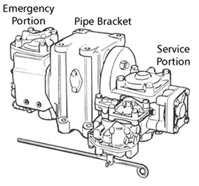
The brake pipe acts to supply compressed air to each car Footnote 202 in the train when the train brakes are released and the system is being charged. The auxiliary reservoir on each car supplies compressed air to the brake cylinder when the brakes are applied and is recharged when the brakes are released. This action is controlled by the CCV reacting to changes in brake pipe pressure.
The brake pipe acts as a signal line to apply or release/recharge the train brakes. The signal is controlled from the automatic brake valve on the lead locomotive by changing the air pressure in the brake pipe. The principle of train air brakes is based on lowering brake pipe pressure to apply the brakes and increasing brake pipe pressure to release the brakes. The train air brake system must be sufficiently charged with compressed air to operate as designed.
When a freight train air brake system is sufficiently charged, the brakes are applied through a controlled reduction in brake pipe pressure. This is called a service reduction. Train brakes can be applied with a minimum application, which is the lightest brake possible, and gradually applied harder in stages until a full service Footnote 203 application is achieved. A service train brake application can be incrementally increased until a full-service brake application is achieved, but it cannot be incrementally released; it can only be fully released.
To apply the train brakes harder than a full-service application requires an emergencyFootnote 204 brake application. This is done by venting the brake pipe air at an uncontrolled rate, allowing the pressure to drop rapidly to 0 psi. Once an emergency brake application is initiated, the drop in brake pipe pressure to 0 psi cannot be stopped.
The CCV on a freight car reacts to an abrupt drop in air pressure by allowing air pressure stored in the emergency reservoir to flow into the brake cylinder. The auxiliary reservoir is also used during an emergency brake application. This causes a faster and higher build-up of brake cylinder pressure, resulting in a harder brake application and a faster stop.
When a normal automatic brake application is required, the locomotive engineer (LE) moves the automatic brake valve handle (Figure A3) to the desired position. This action removes air from the brake pipe at a service rate. As each CCV senses a sufficient reduction in pressure, air flows from the auxiliary reservoir located on each car into that car's brake cylinder, applying the brake shoes to the wheels.

To release the brakes, the LE moves the automatic brake valve handle to the release position. This action allows air to flow from the main reservoir back into the brake pipe, restoring pressure to 90 psi. Sensing an increase in brake pipe air pressure, the CCV on each car allows air to be released from the brake cylinder through its retaining valve, and the brake shoes are removed from the wheels.
To reapply the train brakes after a release requires the brake pipe pressure to again be reduced using the automatic brake valve. Before reapplying the train brakes, the system needs time to recharge. Not allowing sufficient time for the system to recharge may result in the brakes not applying or unintentionally releasing after a short time.
Independent brake system
On a locomotive, the independent brakes are also supplied with air from the main reservoir. Unlike the automatic brake system, the independent brake system is a direct air system. An independent brake valve controls a relay valve that will allow air from the main reservoir to flow into the brake cylinders on the locomotives only.
When a full independent brake application is required, the LE moves the independent brake valve handle (Figure A4) to the full application position, and air pressure is supplied to the locomotive brake cylinders. This causes the brake shoes to apply to only the locomotive wheels. Brake cylinder pressure can also be gradually increased or decreased as needed by moving the brake valve handle in the application zone.
To release the independent brakes, the LE moves the independent brake valve handle to the release position. This causes air to be released from the locomotive’s brake cylinders, and the brake shoes are removed from the locomotive wheels. Air pressure in the locomotive brake cylinders is relative to the position of the independent brake valve handle.
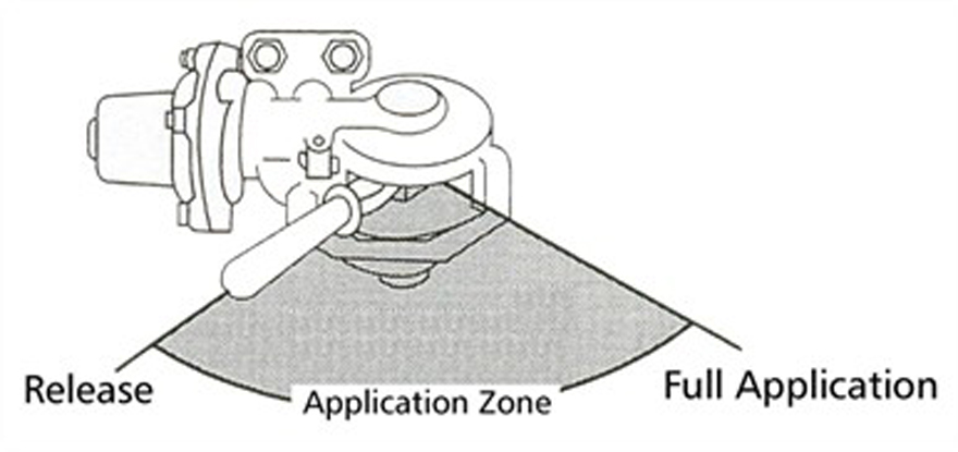
Control valves
Each car is equipped with a CCV, which is comprised of a service and an emergency portion. The train locomotive air compressors supply air pressure to each freight car through the brake pipe. Brake pipe air pressure comes through the branch pipe tee, then is fed to the CCV through the cut-out cock. The CCV supplies compressed air to the combined reservoir, included on each freight car. The combined reservoir comprises 2 separate sections: an auxiliary reservoir (handling the service brake applications), and an emergency reservoir (mainly supplementing air pressure for an emergency brake application).
When the freight car is fully charged (when the brakes are released), the pressure is equal to 90 psi in the brake pipe, as well as in the auxiliary and emergency reservoirs. During an automatic brake application, brake pipe pressure is reduced, which in turn signals the CCV to apply the brakes by directing air from the auxiliary reservoir into the brake cylinder on the freight car, thus extending the piston, moving the brake beams and setting the brake shoes against the wheels.
During each service brake application, the brake pipe and auxiliary reservoir pressures are equal on the freight car. The CCV monitors any pressure differential between the brake pipe and the auxiliary reservoir. Brakes are released when brake pipe pressure increases by 1.5 to 2 psi above auxiliary reservoir pressure.
When an emergency brake application is initiated for the train, it is due to either the LE putting the air brake handle in emergency, or the freight car end hoses coming apart between cars. In either case, the CCVs sense the very rapid discharge of air pressure from brake pipe (brake pipe pressure would drop to 0 psi at a rate of 900-950 feet per second) and directs air pressure from both the auxiliary and emergency reservoirs into the brake cylinder to apply the maximum available braking force and bring the train to a stop.
Finally, when brakes are released, brake cylinder air pressure flows back through the CCV and is exhausted into atmosphere through the retaining valve.
Air flow display
On locomotives equipped with operator display screens, the air flow is displayed in a box identified as “Flow” (Figure A5). The value displayed on the screen indicates the amount of air flow into the brake pipe in cubic feet per minute (CFM). This type of air flow indicator displays 0 when the demand for air falls below 20 CFM.
When the train brake system is being charged, the air flow indicator will display a large value, typically higher than 60 CFM. This indicates that there is a high flow of air into the brake pipe. As the system becomes charged, the value displayed will come down, indicating a decrease of flow.
When the value on the air flow indicator stops falling and stabilizes, it indicates that the demand for air is steady and the system is fully charged. The pressure-maintaining feature of the automatic brake valve will compensate for brake pipe leakage. If there is leakage in the brake pipe, the flow value may not reach 0 CFM when the train brake system is fully charged.
Because the air flow indicator measures the rate of air flow to the brake pipe, it can also indicate
- the rate at which a train is being charged or recharged;
- a heavy demand of air in the brake pipe, if a hose has separated or ruptured; or
- a flow of air into the brake pipe as the pressure-maintaining feature of the automatic brake valve compensates for normal leakage.
If the air flow indicator shows an increased air flow while the brakes are applied, it could indicate that
- the brakes are releasing (unintentional release);
- somewhere in the train, a brake pipe coupling hose has come apart;
- somewhere in the train, there is a hose or brake pipe rupture; or
- there is excessive leakage.
Brake pipe pressure maintaining
Pressure maintaining is a feature of the automatic brake valve that allows air to flow into the brake pipe at a controlled rate to overcome normal brake pipe leakage without causing the brakes on the train to release. During service brake applications, it allows the selected brake pipe pressure reduction to be maintained for long periods of time. This feature allows trains to descend long mountain grades with the brakes applied as needed.
Without brake pipe pressure maintaining, leakage will cause the brake pipe pressure to continue falling after the brakes have been applied. Eventually, the brake pipe pressure will drop to 0 psi. Controlling train speed on long descending grades is difficult without brake pipe pressure maintaining.
Pressure maintaining is always functioning when a locomotive is set up to be the lead or controlling remote locomotive on the train. Pressure maintaining is disabled on locomotives set up for trail operation.Footnote 205
Emergency braking
An emergency brake application is the maximum application of a train’s air brakes during which the brake pipe pressure is rapidly reduced to 0, either from a separation of the brake pipe or operator-initiated action. Following an emergency brake application, the air from the auxiliary and emergency reservoirs combine in the brake cylinder. When brake pipe pressure is below 45 psi, a rapid reduction in brake pipe pressure cannot be relied upon to initiate an emergency brake application.
Pressure retaining valves
A pressure retaining valve, commonly called a retainer, is a manually operated valve that can be used to limit the release of air pressure from the brake cylinder after the automatic brake is released. The retainer has 3 settings, which are set by rotating the handle into the appropriate notches:
- The Direct Exhaust (DE) setting, also known as Exhaust (EX), which lets all the air pressure exhaust to the atmosphere. This is the default setting of the retainers on trains.
- The High Pressure (HP) setting, which is designed to nominally hold up to 20 psi of compressed air in the brake cylinder after the car air brake is released. This may help hold the train in a stationary position or control the speed while the air brake system is being recharged. In a situation where the cylinder pressure is less than 20 psi at the time when the air brake is released, the retainer will initially hold whatever pressure existed at that time.
- The Slow Direct (SD) setting, where brake cylinder pressure is fully depleted to atmosphere, but at a much slower rate, when a brake release is commanded.
The HP and SD settings become effective only after releasing the initial brake application. The use of retainers does not provide any additional brake retarding force while the train brakes remain applied. Rather, the retainers are intended to provide a residual amount of braking force after the train brakes (automatic air brakes) are released.
Dynamic brakes
The DB system is designed to be used as a supplementary braking system to the train air brake system. The DB system operates by electrically converting the traction motors of a moving locomotive into electric generators. One of the characteristics of a generator (traction motor) is to resist rotation when it is producing electricity. This resistance is caused by a magnetic field through which the traction motor armature rotates. The movement of the DB handle controls the strength of the magnetic field and the retardation effort. When DB is applied, traction motors are reversed, exercising a drag or braking effect on the train. The rotation of the traction motor armature through the magnetic field generates a current. This current is then sent to the resistor grids that produce heat. Fans mounted on the locomotive roof cool the resister grids and the heat is dissipated to atmosphere.
When only the locomotive DB is used, compressive or “buff” forces are concentrated behind the locomotives. When DB used in combination with train air brake systems, these forces are more evenly distributed throughout the train. DB use on long mountain grades prevents brake shoe friction fade on the locomotives because the locomotive traction motors provide resistance. There is no contact between wheel treads and brake shoes and no frictional heat is generated. When DB is used to supplement the train air brakes, less air brake force is needed, reducing the likelihood of brake shoe friction fade on the train and making it possible to reserve train air brake capacity for use in the event of an emergency.
Appendix B – Inspection and testing of air brake systems
No. 1 brake test
In accordance with the requirements of Transport Canada–approved Railway Freight and Passenger Train Brake Inspection and Safety Rules and CP’s General Operating Instructions, the No. 1 brake test is conducted by certified car inspectors at locations where trains are made up or at specified locations for trains in service. The inspectors conducting the test must verify the brake pipe integrity and continuity, and the brake rigging condition on each car to ensure that the brakes meet the minimum requirements.
During the test, the brakes are applied and then the brake cylinder pistons are visually verified to ensure that the brakes have applied on each car and that the extension of brake cylinder piston is within specifications. After the brakes have been released, a second visual verification of the brake cylinder pistons is performed on each car to ensure that the brakes have in fact released. All trains departing designated safety inspection locations require at least 95% of the air brakes to be operative.Footnote 206
The Transport Canada–approved Railway Freight and Passenger Train Brake Inspection and Safety Rules set the requirement for a No. 1 brake test as follows:
11. No.1 BRAKE TEST
11.1 A No.1 brake test shall be performed by a certified car inspector(s) at safety inspection locations on:
a) trains that are made up at that location;
b) cars added to a train at that location;
c) cars that are interchanged.
d) If a train is made up at other than a safety inspection location, a No. 1 brake test will be performed at the safety inspection location designated for that train by the railway company in the direction of travel.
11.2 Exceptions: A No.1 brake test is not required on:
a) trains operating over main tracks, between yards, up to a maximum of a thirty (30) mile (fifty (50) kilometre) radius. Such trains shall be engaged exclusively in the setting off or lifting of equipment at industry(s), and/or the transfer of equipment between yards, and they shall be filed with the Department.
b) a block swap of cars that have been off air for no more than 24 hours or 48 hours after notifying the department.
11.3 A No.1 brake test shall verify:
a) the integrity and continuity of the brake pipe;
b) that the condition of the brake rigging on each car in the train meets the minimum requirement specified in Sections 20, 21 and 22 of these Rules;
c) that the application and release of the brakes on each car is performed by visible verification of the piston or brake indicator device displacement; and
d) that piston travel on each car is within the specified limits.
11.4 A pull-by inspection by a certified car inspector may be performed to verify the release of the train brakes.
11.5 Certified car inspectors shall report, in accordance with company procedures/work instructions, the results of all brake tests performed. Any brake system defect(s) discovered during the brake test and not repaired prior to departure shall be documented as bad order and reported to the conductor, or in his or her absence, the locomotive engineer. The conductor/engineer shall update the train brake status system with the identified defect(s). The results of the tests performed by certified car inspectors shall be retained for ninety-two (92) days.
11.6 After completing a No.1 brake test, a train may depart from a safety inspection location with ninety-five (95) percent of the train brakes operative, once every reasonable effort has been made to maintain one hundred (100) percent operative brakes. This requirement does not apply to cars referred to in Subsection 8.4 of these Rules.
11.7 A No. 1 brake test is not required at an interchange point and/or when entering Canada provided the locomotive engineer has access to records that indicate that a No.1 brake test, as per these Rules, or an initial terminal brake test by mechanical personnel in the United States, was performed.Footnote 207
Single car test
A single car testFootnote 208 (SCT) verifies the operation of the air brake system on an individual car. Although testing can be performed outside on a designated repair track, the test is more often performed inside a repair shop facility at room temperature. The device used to conduct this test is equipped with a special control valve and flowmeter to verify the essential braking functions. During the test, pressure loss is measured in the brake cylinders for 4 minutes following a reduction of 10 psi in the brake pipe. The allowable pressure loss is 1 psi (or less).According to the Field Manual of the AAR Interchange Rules, a SCT is required:
- when a car is on a repair track or in a shop and has not received a SCT for more than a year;
- when a car has been in service without having had a SCT for a period of 5 years; or
- when a car has been in service without having a test done for a period of 5 years (8 years for new cars).Footnote 209
The automated single car test (ASCT) is routinely used by railway maintenance personnel for inspecting, testing, and diagnosing car air brake system issues. In addition to testing for pronounced leakage (system, brake pipe, retainer leakage, reservoir), the ASCT will test such things as minimum application, service valve stability, service release, emergency vent valve operation, emergency accelerated release, and the operation of the empty/load device.
The test is not actually a single test, but rather a test program involving a progressive series of test steps, each individually designed to assess a particular aspect of air brake performance. Each test step must be successfully completed before progressing to the next step. If a given test step fails, the underlying problem must be investigated and repaired. Once the repair is completed, the test program is restarted to allow the test program to progress to the next test level. In a shop environment, the sequence of testing, troubleshooting, repairing, and retesting would be followed until all test steps are successfully passed.
Brake cylinder leakage test
The test procedure for brake cylinder leakage involves the following steps:- Apply a 10 psi brake reduction.
- Wait 3 minutes after the brake pipe pressure has stabilized at 80 psi.
- Take a reading of the pressure on the brake cylinder gauge.
- Wait 1 minute.
- Recheck the brake cylinder pressure.
Appendix C – Maintenance history of the cars on the occurrence train
The 112 grain cars on the train were assembled from 3 separate fleets of hopper cars, each with a different maintenance history. The investigation reviewed the replacement history of brake components, in particular the brake shoes, the brake cylinders, and the car control valves (CCVs).
The cars from each fleet were equipped with different brake systems and brake configurations (Table C1). The air brake arrangements on all cars were compliant with Association of American Railroads (AAR) specifications S-400 and S-401.
| Fleet | Number of cars | Brake cylinder type | Comments |
|---|---|---|---|
| SOO | 29 | Truck-mounted | Wabco TMX and New York Air Brake (NYAB) TMB-60 equipped with automatic slack adjuster |
| SOO | 22 | Body-mounted | Wabco or NYAB equipped with automatic slack adjuster |
| Leased | 21 | Body-mounted | Wabco or NYAB equipped with automatic slack adjuster |
| Canadian Pacific* | 40 | Truck-mounted | Wabcopac/Nycopac not equipped with slack adjuster |
* 2 cars in the CP 384000-384999 series and 38 Government of Canada cars in the CP 600000–608591 series
Brake shoe replacements
Table C2 breaks down the total number of brake shoes replaced on the 112 cars during the previous 5 years according to the temperature categories used for the wheel temperature detector (WTD) data in section 1.19.2.3: cold (less than 100 °F), marginal (from 100 °F to 150 °F) and adequate (greater than 150 °F).
| Car average temperature ranking | Number of cars | Brake shoes replaced | Percentage of brake shoes replaced per car |
|---|---|---|---|
| Adequate | 67 | 858 | 12.8 |
| Marginal | 25 | 333 | 13.3 |
| Cold | 20 | 258 | 12.9 |
Car control valve replacements
The maintenance history indicates that a total of 70 CCV portions were replaced on the 112 cars during the last 5 years. Considering that each car has 2 valve portions (a service portion and an emergency portion), this represents a replacement rate of 31% in the 5 years. Table C3 breaks down the number of valve replacements for cars in each wheel temperature category.
| Car average temperature ranking | Number of cars | Valves replaced | Percentage of valves replaced per car |
|---|---|---|---|
| Adequate | 67 | 29 | 21.6 |
| Marginal | 25 | 22 | 44.0 |
| Cold | 20 | 19 | 47.5 |
Single car tests
Table C4 shows the total number of single car tests performed on the 112 cars during the last 5 years, broken down by the temperature categories.
| Car average temperature ranking | Number of cars | Single car tests | Percentage of single car tests per car |
|---|---|---|---|
| Adequate | 67 | 105 | 1.57 |
| Marginal | 25 | 57 | 2.28 |
| Cold | 20 | 55 | 2.75 |
Brake cylinder replacements
There are no AAR requirements to service or replace brake cylinders on freight cars on a time-based interval. The repair history for the 112 cars shows that 23 cars (20.5%) had received brake cylinder replacement or servicing in the last 5 years due to a failed single car test (Table C5).
| Brake cylinder type | Number of cars | Cars with cylinders replaced (%) |
|---|---|---|
| Truck-mounted Wabcopac | 40 | 14 (35%) |
| Truck-mounted Wabco TMX | 51 | 7 (13.7%) |
| Body-mounted | 21 | 2 (9.5%) |
| Total | 112 | 23 (20.5%) |
Appendix D – Itemized list of train handling events
The tables in this appendix describe train handling events compiled from locomotive event recorder (LER) data. The LER data from the mid-train remote locomotive (UP 5359) were used as the primary source of information. Although the locomotive was extensively damaged in the derailment, the LER memory module survived the accident and the LER data were successfully retrieved. Selected LER information from the tail-end remote locomotive (CEFX 1040) was included as well, where necessary. The data cover train handling events leading up to and including the train stopping in emergency on Field Hill.
Locomotive event recorder data for train handling events, by event
In these tables,
- “H/E Mile” refers to the mile at which the front of the head-end locomotive was located.
- “TE/DB (kip)”Footnote 210 refers to the force, in kilopounds, produced due to the application of tractive effort or dynamic brake (DB).
- “ER (psi)” refers to the pressure, in pounds per square inch, produced by the equalizing reservoir.
- “BPP (psi)” refers to the brake pipe pressure in pounds per square inch.
- “IND (psi)” refers to the pressure, in pounds per square inch, produced by the locomotive independent brake.
- Air flow values do not represent total brake pipe flow; they represent only the flow from the air brake system in the mid-remote locomotive (UP 5259), which was 1 of the 3 operative sources of compressed air on the train.
- The DB changes shown are those DB levels concurrent with changes to speed and air brake.
| Item | Time (MST) | H/E Mile | Speed (mph) | Throttle position | TE/DB (kips) | DB notch | ER (psi) | BPP (psi) | Air flow (CFM) | IND (psi) |
|---|---|---|---|---|---|---|---|---|---|---|
| 1 | 19:02:04 | 105.71 | 22 | T6 | 46 | 0 | 89 | 88 | 0 | 0 |
| 2 | 19:07:18 | 106.96 | 10 | T3 | 36 | 0 | 82 | 81 | 0 | 0 |
| 3 | 19:07:31 | 107.00 | 9 | T2 | 17 | 0 | 79 | 79 | 0 | 0 |
| 4 | 19:09:40 | 107.14 | 0 | Idle | 0 | 0 | 80 | 78 | 0 | 53 |
| Item | Time (MST) | H/E Mile | Speed (mph) | Throttle position | TE/DB (kips) | DB notch | ER (psi) | BPP (psi) | Air flow (CFM) | IND (psi) |
|---|---|---|---|---|---|---|---|---|---|---|
| 5 | 20:19:22 | 107.15 | 0 | T1 | 0 | 0 | 89 | 85 | 89 | 71 |
| 6 | 20:19:39 | 107.15 | 1 | T2 | 51 | 0 | 89 | 87 | 78 | 0 |
| 7 | 20:19:50 | 107.15 | 2 | T3 | 51 | 0 | 90 | 87 | 67 | 0 |
| 8 | 20:21:53 | 106.77 | 18 | T2 | 16 | 0 | 90 | 88 | 29 | 0 |
| 9 | 20:22:03 | 106.72 | 18 | T1 | 4 | 0 | 90 | 88 | 27 | 0 |
| 10 | 20:22:31 | 106.57 | 19 | Idle | 0 | 0 | 90 | 88 | 26 | 0 |
| Item | Time (MST) | H/E Mile | Speed (mph) | Throttle position | TE/DB (kips) | DB notch | ER (psi) | BPP (psi) | Air flow (CFM) | IND (psi) |
|---|---|---|---|---|---|---|---|---|---|---|
| 11 | 20:22:53 | 106.44 | 21 | Idle | 0 | Setup | 90 | 88 | 22 | 0 |
| 12 | 20:23:25 | 106.25 | 20 | Idle | 70 | 6 | 90 | 88 | 0 | 0 |
| Item | Time (MST) | H/E Mile | Speed (mph) | Throttle position | TE/DB (kips) | DB notch | ER (psi) | BPP (psi) | Air flow (CFM) | IND (psi) |
|---|---|---|---|---|---|---|---|---|---|---|
| 13 | 20:24:41 | 105.85 | 16 | Idle | 81 | 7 | 79 | 79 | 0 | 0 |
| 14 | 20:25:10 | 105.76 | 4 | Idle | 25 | 8 | 61 | 62 | 0 | 30 |
| Item | Time (MST) | H/E Mile | Speed (mph) | Throttle position | TE/DB (kips) | DB notch | ER (psi) | BPP (psi) | Air flow (CFM) | IND (psi) |
|---|---|---|---|---|---|---|---|---|---|---|
| 15 | 20:25:47 | 105.75 | 0 | T2 | 0 | 0 | 90 | 82 | 106 | 73 |
| 16 | 20:52:52 | 105.75 | 0 | T3 | 53 | 0 | 89 | 83 | 103 | 18 |
| 17 | 20:26:18 | 105.75 | 1 | T4 | 87 | 0 | 89 | 85 | 79 | 0 |
| 18 | 20:27:26 | 105.84 | 6 | T5 | 76 | 0 | 89 | 88 | 56 | 0 |
| 19 | 20:27:54 | 105.90 | 9 | T6 | 82 | 0 | 89 | 88 | 45 | 0 |
| 20 | 20:28:04 | 105.93 | 9 | T7 | 102 | 0 | 89 | 88 | 41 | 0 |
| 21 | 20:28:25 | 105.99 | 11 | T8 | 108 | 0 | 89 | 88 | 36 | 0 |
| 22 | 20:53:48 | 116.20 | 21 | T8 | 67 | 0 | 89 | 88 | 0 | 0 |
| 23 | 21:17:20 | 121.50 | 12 | T8 | 110 | 0 | 89 | 88 | 0 | 0 |
| Item | Time (MST) | H/E Mile | Speed (mph) | Throttle position | TE/DB (kips) | DB notch | ER (psi) | BPP (psi) | Air flow (CFM) | IND (psi) |
|---|---|---|---|---|---|---|---|---|---|---|
| 24 | 21:20:29 | 122.15 | 12 | T7 | 105 | 0 | 89 | 88 | 0 | 0 |
| 25 | 21:20:32 | 122.16 | 11 | T6 | 94 | 0 | 89 | 88 | 0 | 0 |
| 26 | 21:20:36 | 122.17 | 10 | T5 | 71 | 0 | 89 | 88 | 0 | 0 |
| 27 | 21:20:47 | 122.20 | 9 | T4 | 57 | 0 | 89 | 88 | 0 | 0 |
| 28 | 21:21:00 | 122.24 | 8 | T5 | 54 | 0 | 89 | 88 | 0 | 0 |
| 29 | 21:21:17 | 122.28 | 9 | T6 | 81 | 0 | 89 | 88 | 0 | 0 |
| 30 | 21:21:26 | 122.31 | 12 | T7 | 103 | 0 | 89 | 88 | 0 | 0 |
| 31 | 21:22:38 | 122.52 | 12 | T5 | 84 | 0 | 89 | 88 | 0 | 0 |
| 32 | 21:22:39 | 122.52 | 12 | T6 | 74 | 0 | 89 | 88 | 0 | 0 |
| 33 | 21:22:42 | 122.53 | 12 | T5 | 69 | 0 | 89 | 88 | 0 | 0 |
| 34 | 21:23:20 | 122.66 | 12 | T3 | 47 | 0 | 89 | 88 | 0 | 0 |
| 35 | 21:23:24 | 122.67 | 10 | T2 | 24 | 0 | 89 | 88 | 0 | 0 |
| 36 | 21:23:44 | 122.74 | 8 | T1 | 10 | 0 | 89 | 88 | 0 | 0 |
| 37 | 21:24:07 | 122.80 | 5 | Idle | 0 | 0 | 89 | 88 | 0 | 0 |
| 38 | 21:24:37 | 122.85 | 2 | T1 | 0 | 0 | 89 | 88 | 0 | 0 |
| 39 | 21:25:30 | 122.91 | 3 | T2 | 28 | 0 | 89 | 88 | 0 | 0 |
| 40 | 21:25:53 | 122.93 | 3 | T1 | 16 | 0 | 89 | 88 | 0 | 0 |
| Item | Time (MST) | H/E Mile | Speed (mph) | Throttle position | TE/DB (kips) | DB notch | ER (psi) | BPP (psi) | Air flow (CFM) | IND (psi) |
|---|---|---|---|---|---|---|---|---|---|---|
| 41 | 21:25:55 | 122.93 | 3 | T2 | 21 | 0 | 89 | 88 | 0 | 0 |
| 42 | 21:26:44 | 122.97 | 3 | T3 | 46 | 0 | 89 | 88 | 0 | 0 |
| 43 | 21:27:44 | 123.06 | 7 | T2 | 36 | 0 | 89 | 88 | 0 | 0 |
| Item | Time (MST) | H/E Mile | Speed (mph) | Throttle position | TE/DB (kips) | DB notch | ER (psi) | BPP (psi) | Air flow (CFM) | IND (psi) |
|---|---|---|---|---|---|---|---|---|---|---|
| 44 | 21:27:49 | 123.07 | 7 | T3 | 21 | 0 | 89 | 88 | 0 | 0 |
| Item | Time (MST) | H/E Mile | Speed (mph) | Throttle position | TE/DB (kips) | DB notch | ER (psi) | BPP (psi) | Air flow (CFM) | IND (psi) |
|---|---|---|---|---|---|---|---|---|---|---|
| 45 | 21:28:13 | 123.12 | 8 | T3 | 41 | 0 | 84 | 88 | 0 | 0 |
| 46 | 21:28:27 | 123.15 | 9 | T3 | 38 | 0 | 83 | 81 | 0 | 0 |
| 47 | 21:28:34 | 123.17 | 9 | T2 | 29 | 0 | 83 | 81 | 0 | 0 |
| Item | Time (MST) | H/E Mile | Speed (mph) | Throttle position | TE/DB (kips) | DB notch | ER (psi) | BPP (psi) | Air flow (CFM) | IND (psi) |
|---|---|---|---|---|---|---|---|---|---|---|
| 48 | 21:28:37 | 123.18 | 9 | T2 | 17 | 0 | 83 | 81 | 21 | 0 |
| Item | Time (MST) | H/E Mile | Speed (mph) | Throttle position | TE/DB (kips) | DB notch | ER (psi) | BPP (psi) | Air flow (CFM) | IND (psi) |
|---|---|---|---|---|---|---|---|---|---|---|
| 49 | 21:28:47 | 123.20 | 8 | T1 | 8 | 0 | 83 | 81 | 27 | 0 |
| 50 | 21:29:23 | 123.28 | 7 | T2 | 11 | 0 | 83 | 81 | 29 | 0 |
| 51 | 21:29:39 | 123.32 | 6 | T3 | 26 | 0 | 83 | 81 | 30 | 0 |
| 52 | 21:30:00 | 123.36 | 7 | T3 | 47 | 0 | 83 | 81 | 32 | 0 |
| 53 | 21:31:17 | 123.54 | 10 | T2 | 23 | 0 | 83 | 81 | 29 | 0 |
| 54 | 21:31:33 | 123.59 | 10 | T1 | 9 | 0 | 83 | 81 | 30 | 0 |
| 55 | 21:31:58 | 123.66 | 10 | T2 | 9 | 0 | 83 | 81 | 28 | 0 |
| 56 | 21:32:16 | 123.71 | 10 | T1 | 9 | 0 | 83 | 81 | 29 | 0 |
| Item | Time (MST) | H/E Mile | Speed (mph) | Throttle position | TE/DB (kips) | DB notch | ER (psi) | BPP (psi) | Air flow (CFM) | IND (psi) |
|---|---|---|---|---|---|---|---|---|---|---|
| 57 | 21:32:29 | 123.75 | 10 | Idle | 0 | 0 | 83 | 81 | 32 | 0 |
| Item | Time (MST) | H/E Mile | Speed (mph) | Throttle position | TE/DB (kips) | DB notch | ER (psi) | BPP (psi) | Air flow (CFM) | IND (psi) |
|---|---|---|---|---|---|---|---|---|---|---|
| 58 | 21:32:39 | 123.78 | 10 | Idle | 0 | Setup | 83 | 81 | 33 | 0 |
| 59 | 21:33:16 | 123.90 | 12 | Idle | 7 | 1 | 83 | 81 | 32 | 0 |
| Item | Time (MST) | H/E Mile | Speed (mph) | Throttle position | TE/DB (kips) | DB notch | ER (psi) | BPP (psi) | Air flow (CFM) | IND (psi) |
|---|---|---|---|---|---|---|---|---|---|---|
| 60 | 21:36:59 | 124.79 | 19 | Idle | 78 | 8 | 80 | 79 | 0 | 0 |
| 61 | 21:37:15 | 124.88 | 19 | Idle | 89 | 8 | 80 | 78 | 20 | 0 |
| Item | Time (MST) | H/E Mile | Speed (mph) | Throttle position | TE/DB (kips) | DB notch | ER (psi) | BPP (psi) | Air flow (CFM) | IND (psi) |
|---|---|---|---|---|---|---|---|---|---|---|
| 62 | 21:38:34 | 125.24 | 14 | Idle | 0 | 0 | 80 | 78 | 28 | 0 |
| 63 | 21:38:44 | 125.28 | 14 | T2 | 0 | 0 | 80 | 78 | 28 | 0 |
| 64 | 21:38:53 | 125.32 | 14 | T3 | 12 | 0 | 80 | 78 | 29 | 0 |
| 65 | 21:39:09 | 125.38 | 13 | T2 | 20 | 0 | 80 | 78 | 28 | 0 |
| 66 | 21:39:18 | 125.42 | 13 | T3 | 13 | 0 | 80 | 78 | 27 | 0 |
| 67 | 21:39:42 | 125.51 | 13 | T4 | 31 | 0 | 80 | 78 | 27 | 0 |
| Item | Time (MST) | H/E Mile | Speed (mph) | Throttle position | TE/DB (kips) | DB notch | ER (psi) | BPP (psi) | Air flow (CFM) | IND (psi) |
|---|---|---|---|---|---|---|---|---|---|---|
| 68 | 21:39:57 | 125.56 | 12 | T3 | 31 | 0 | 80 | 78 | 28 | 0 |
| 69 | 21:39:59 | 125.57 | 12 | T2 | 19 | 0 | 80 | 78 | 27 | 0 |
| 70 | 21:40:29 | 125.67 | 11 | T1 | 7 | 0 | 80 | 78 | 28 | 0 |
| 71 | 21:40:30 | 125.68 | 11 | T2 | 8 | 0 | 80 | 78 | 28 | 0 |
| 72 | 21:40:40 | 125.71 | 11 | T1 | 8 | 0 | 80 | 78 | 28 | 0 |
| 73 | 21:40:59 | 125.76 | 10 | T2 | 7 | 0 | 80 | 78 | 30 | 0 |
| 74 | 21:41:03 | 125.77 | 10 | T3 | 21 | 0 | 80 | 78 | 30 | 0 |
| 75 | 21:41:21 | 125.83 | 10 | T2 | 26 | 0 | 80 | 78 | 29 | 0 |
| 76 | 21:41:25 | 125.84 | 10 | T1 | 8 | 0 | 80 | 78 | 29 | 0 |
| 77 | 21:41:36 | 125.87 | 10 | T2 | 8 | 0 | 80 | 78 | 29 | 0 |
| 78 | 21:41:51 | 125.91 | 10 | T1 | 9 | 0 | 80 | 78 | 28 | 0 |
| Item | Time (MST) | H/E Mile | Speed (mph) | Throttle position | TE/DB (kips) | DB notch | ER (psi) | BPP (psi) | Air flow (CFM) | IND (psi) |
|---|---|---|---|---|---|---|---|---|---|---|
| 79 | 21:41:59 | 125.93 | 10 | Idle | 0 | 0 | 80 | 78 | 28 | 0 |
| 80 | 21:42:08 | 125.96 | 10 | Idle | 0 | Setup | 80 | 78 | 27 | 0 |
| 81 | 21:42:41 | 126.05 | 8 | Idle | 66 | 6 | 80 | 78 | 25 | 0 |
| 82 | 21:45:22 | 126.34 | 7 | Idle | 0 | 0 | 79 | 78 | 31 | 0 |
| 83 | 21:45:28 | 126.36 | 9 | Idle | 0 | Setup | 79 | 78 | 30 | 0 |
| Item | Time (MST) | H/E Mile | Speed (mph) | Throttle position | TE/DB (kips) | DB notch | ER (psi) | BPP (psi) | Air flow (CFM) | IND (psi) |
|---|---|---|---|---|---|---|---|---|---|---|
| 84 | 21:46.01 | 126.46 | 14 | Idle | 39 | 3 | 77 | 76 | 0 | 0 |
| 85 | 21:46:29 | 126.58 | 15 | Idle | 90 | 8 | 78 | 76 | 20 | 0 |
| Item | Time (MST) | H/E Mile | Speed (mph) | Throttle position | TE/DB (kips) | DB notch | ER (psi) | BPP (psi) | Air flow (CFM) | IND (psi) |
|---|---|---|---|---|---|---|---|---|---|---|
| 86 | 21:46:46 | 126.66 | 16 | Idle | 91 | 8 | 75 | 74 | 0 | 0 |
| 87 | 21:47:19 | 126.82 | 19 | Idle | 83 | 8 | 73 | 72 | 0 | 0 |
| 88 | 21:47:48 | 126.98 | 21 | Idle | 86 | 8 | 70 | 70 | 0 | 1 |
| 89 | 21:48:05 | 127.09 | 22 | Idle | 37 | 8 | 69 | 68 | 0 | 61 |
| 90 | 21:48:10 | 127.12 | 22 | Idle | 14 | 0 | 68 | 33 | 0 | 60 |
| Item | Time (MST) | H/E Mile | Speed (mph) | Throttle position | TE/DB (kips) | DB notch | ER (psi) | BPP (psi) | Air flow (CFM) | IND (psi) |
|---|---|---|---|---|---|---|---|---|---|---|
| 91 | 21:48:11 | 127.13 | 23 | Idle | 0 | 0 | 62 | 3 | 0 | 51 |
| 92 | 21:48:12 | 127.13 | 23 | Idle | 0 | 0 | 57 | 0 | 0 | 48 |
| 93 | 21:49:33 | 127.46 | 0 | Idle | 0 | 0 | 0 | 0 | 0 | 44 |
Appendix E – Mechanical testing and human factors assessment of train securement using hand brakes
Although hand brakes were not applied on the occurrence train, in support of this investigation, the Operational Services Branch of the TSB conducted mechanical testing and a human factors assessment of issues related to hand brake securement of freight trains on mountain grades. The objective was to determine how many hand brakes would have been needed to hold the train stationary on Field Hill, and whether it would have been possible for a lone conductor to apply on average sufficient torque to the required hand brakes to ensure that the train had the retarding force necessary to remain stationary.
Regulatory requirements regarding the number of hand brakes to apply on a train
As part of the study, the TSB reviewed regulatory requirements dictating the number of hand brakes to apply on a train in various situations.
Canadian Rail Operating Rules, Rule 112: Securing Unattended Equipment
CROR Rule 112 covers the securement requirements for unattended equipment. Because the occurrence train was not left unattended, Rule 112 did not apply. However, a review of this rule still provides valuable information for the purpose of this study, as it lists the minimum number of hand brakes that need to be applied on various grades and for different train weights when trains are unattended.
Given the occurrence train’s weight of approximately 15 000 tons and the average 2.2% descending grade, had the train been left unattended, a minimum of 98 hand brakes would have been needed to secure it, according to the chart in CROR Rule 112 (g).Footnote 211
Transport Canada Ministerial Order 19-03
Following this derailment, Transport Canada issued Ministerial Order MO 19-03 requiring train crews to immediately secure their trains with a pre-determined number of hand brakes (based on train tonnage and descending grade) following an emergency stop on mountain grades.
To meet the requirements of this Ministerial Order on the occurrence train, given the train tonnage and grade, it would have been necessary to apply hand brakes on 98 cars after the train was stopped in emergency on Field Hill.
Canadian Rail Operating Rules, Rule 66: Securing Equipment after an Emergency Brake Application on Grade
On 24 April 2020, the Minister of Transport approved CROR Rule 66, which covers the securement requirements after an emergency brake application on grade. This rule came into force on 24 June 2020 and replaced MO 19-03.
Given the occurrence train’s tonnage and the mountain grade, to meet the requirements of Rule 66, it would have been necessary to apply 75 hand brakes on the occurrence train after it stopped in emergency, which is 23 hand brakes less than the number required by CROR Rule 112.
Mechanical testing of the hand brakes on the recovered cars
The TSB performed mechanical testing on the 13 grain cars recovered from the occurrence site to determine the performance and efficiency of their hand brakes. The 13 cars represented 4 different car builders and ranged from 3 to 43 years of service. The mechanical testing was conducted at a Canadian Pacific car shop in Port Coquitlam, British Columbia.
The testing used various calibrated apparatus to measure the input torque and output forces involved, and followed a thorough test plan which covered various brake application scenarios.
Hand brake effectiveness on steep grades
CROR Rule 112 identifies the manner in which “hand brake effectiveness” must be tested. Item (vi) of the Rule states the following:
(vi) Testing Hand Brake Effectiveness
When testing the effectiveness of hand brakes, ensure all air brakes are released and:
(a) Allow the slack to adjust. It must be apparent when slack runs in or out, that the hand brakes are sufficient to prevent the equipment from moving; or
(b) Apply sufficient tractive effort to determine that the hand brakes prevent the equipment from moving when tractive effort is terminated.Footnote 212
On steep grades, such as where the occurrence train was stopped, it would not be possible to release all the air brakes to test for applied hand brake effectiveness. Therefore, when trains are stopped in emergency on steep grades, they are secured by applying the pre-determined number of hand brakes on top of the emergency brake application.
In such conditions, generating a sufficient amount of retarding force to hold a train stationary depends on the applied hand brake force and on the amount of brake cylinder pressure (BCP) that is produced due to applying the train brakes in emergency.
The hand brake testing on the 13 recovered cars attempted to evaluate the net braking force that would have resulted from the combination of hand brakes and emergency air brakes on the occurrence train.
Hand brake net braking ratio
Grain hopper cars are equipped with a 22-inch diameter vertical hand-wheel-activated hand brake. These hand brakes are required by the AAR to generate a net braking ratio (NBR) greater than, or equal to, 10% of the gross weight of the loaded car at the time of manufacture. The AAR design specification also states that service wear should not result in the hand brake NBR being reduced below 6.5% on a rail car.Footnote 213
The hand brake NBR is determined by dividing the sum of the generated brake shoe force at each hand brake wheel by the gross weight of the car, based on a force of 125 pounds applied at the hand brake wheel (115 foot-pounds of torque). The hand brake is required to generate the minimum NBR at a chain force of 3350 pounds.Footnote 214
Testing objectives
The testing performed on the recovered cars consisted of baseline tests and tests simulating the conditions of the hand brakes applied over an emergency brake application.
Baseline tests were conducted with 2 primary objectives:
- to verify that the hand brake on each car met the minimum NBR per design requirements, and
- to determine, for a range of input torques on the hand brake wheel, the relationship between the input torque and the braking ratio.
Tests were then performed on the cars with their brakes applied in emergency. The primary objective of these tests was to examine hand brake retention as the air pressure in the brake cylinder decreased from a full emergency application to zero.
Test conclusions
Testing could not be performed on 2 of the 13 cars due to excessive brake beam rotation causing damage to the load sensors.
Four of the remaining 11 cars failed to meet the 6.5% minimum NBR design criterion given by the AAR, even at maximum torque value of 110 foot-pounds.
When the brake cylinders had leaked from an emergency application pressure to 25 psi, cars required at least 30 foot-pounds of torque to achieve a minimum NBR of 6.5%.
With only 10 psi BCP (minimum brake application), the cars required 75 foot-pounds or greater of input torque to the hand brake wheel to achieve an NBR of 6.5%.
If the hand brakes on the cars generated only the required design minimum NBR of 6.5%, as many as 111 hand brakes may have been needed to secure the occurrence consist (112 cars) on this grade, depending on the coefficient of friction (COF) of the brake shoes.
For an average value of 55 foot-pounds of torque at the hand brake wheel (average value of field tests conducted by the TSB), securing the occurrence train on the 2.2% grade would have required a minimum BCP of 10 psi as well as 73 to 102 hand brakes applied (depending on the COF of the brake shoes, which ranged from 0.3 to 0.4).
For an average BCP of 25 psi on the freight cars, which is considered low (emergency BCP is 77 psi for a fully charged car with no leakage), the train would remain stationary with 48 to 67 hand brakes, depending on the COF of the brake shoes, which ranged from 0.3 to 0.4.
Table E1 shows how many hand brakes would be needed to hold the 15 000-ton occurrence train on the 2.2% descending grade of Field Hill, assuming 55 foot-pounds input torque, and a coefficient of friction in the range of 0.3 to 0.4. In the presence of brake cylinder leakage, an increasingly higher number of hand brakes would be needed as the pressure drops.
| Coefficient of friction | Number of hand brakes required based on average brake cylinder pressure | ||||||
|---|---|---|---|---|---|---|---|
| 77 psi** | 65 psi | 50 psi | 35 psi | 25 psi | 10 psi | 0 psi | |
| 0.30 | 42 | 40 | 46 | 55 | 67 | 102 | 162 |
| 0.31 | 40 | 39 | 44 | 53 | 64 | 98 | 156 |
| 0.32 | 39 | 37 | 43 | 51 | 62 | 95 | 151 |
| 0.33 | 37 | 36 | 41 | 50 | 60 | 92 | 146 |
| 0.34 | 36 | 35 | 40 | 48 | 58 | 88 | 141 |
| 0.35 | 35 | 34 | 38 | 46 | 56 | 86 | 136 |
| 0.36 | 34 | 33 | 37 | 45 | 54 | 83 | 132 |
| 0.37 | 33 | 32 | 36 | 44 | 52 | 80 | 128 |
| 0.38 | 32 | 31 | 35 | 42 | 51 | 78 | 124 |
| 0.39 | 31 | 30 | 34 | 41 | 49 | 75 | 120 |
| 0.40 | 30 | 29 | 33 | 40 | 48 | 73 | 116 |
* The numbers in this table assume a net hand brake ratio of 6.5%.
** A brake cylinder pressure of 77 psi corresponds to the pressure after an emergency brake application, when there is no brake cylinder leakage.
For an average hand brake torque value of 75 foot-pounds, the occurrence train would not need any additional BCP to hold it on the grade if between 112 and 83 hand brakes were applied (depending on the COF of the brake shoes, which ranged from 0.3 to 0.4)
Human performance assessment of the task of applying hand brakes
Ministerial Order MO 19-03 raised the possibility that hand brakes would be mandatory in more situations. It was important therefore during the hand brake testing to benchmark the modified single-conductor hand brake application task from a human performance perspective.
The primary objective of the human performance assessment of applying hand brakes was to predict the magnitude of retarding forces that could be generated by train crews to secure a heavy train stopped on a grade in operating conditions similar to that of the occurrence. The objectives were to
- quantify the average torque an operator can apply for a high number of hand brake applications;
- quantify the assumed degradation of torque applied along approximately 100 grain cars and the time required to complete the task; and
- analyze whether a lone conductor could secure a train effectively using hand brakes alone.
The testing was organized as an independent assessment during summer temperatures on level grade, reflecting ideal environmental conditions for participants. Operating on mountain grade in winter conditions with winter personal protective equipment would greatly increase the difficulty level of applying hand brakes.
The testing was performed on a cut of 115 grain cars. The cars were from several different manufacturers and had representation from a range of build dates. The cut of cars was located along a length of track with road access on each end and bordered on either side by farmland in Coalhurst, Alberta.
Seven participants (5 male and 2 female) of varying stature applied hand brakes to the first 100 cars. Half of the cars had BCP that replicated the condition of an emergency brake application, and the other half replicated the condition of cars with no air brake application. For safety, the remaining 15 cars were marked out of bounds and had their hand brake applied as an anchor for the entire cut.
The National Aeronautics and Space Administration (NASA) task load index (TLX) tool was used to collect and interpret participants’ subjective workloadFootnote 215 ratings in completing the task, targeting variables thought to influence efficiency (i.e., anthropometric variation, physical effort, cognitive workload, and individual technique).
The following assessments were done for each of the test participants:
- time required to complete the task
- torque values applied and average torque value for all 100 cars
- endurance evaluations
- movement along pathway, entraining and detraining times
- post-activity feedback
The time, effort, and performance of each participant was recorded during and after each individual assessment. Various anthropometric measurements were collected and a workload questionnaire administered to compare participants’ effort and physical condition before, during, and after the task. The effects of car design and condition on participant performance were also recorded.
The results from these assessments are summarized below.
- The average time required to board a car and apply a single hand brake was 40.2 seconds.
- The average time required to apply 100 hand brakes was 2 hours and 5 minutes.
- The average achievable input torque over 100 hand brakes was 55 foot-pounds.
- The current hand brake design requires an input torque of 75 to 103 foot-pounds, depending on the COF, to secure the occurrence train with 84 hand brakes.
- Variations in workstation design (e.g., boarding ladders, grab irons) at the hand brake interface increased the difficulty of the task.
- The design of the hand brake wheel caused superficial injury to participants’ hands even though they wore 2 pairs of work gloves.
- The average NASA TLX subjective workload score was 51/100, which is a moderate level of effort considering the physical and cognitive demands placed on the participants.
- Safe and effective successive application of 100 hand brakes would be unlikely for a person with reduced physical fitness (i.e., poor cardiovascular endurance and/or reduced musculoskeletal strength).
Brake stick
As an addendum to the human performance assessment, a brake stick was briefly trialled to determine its effectiveness.
A brake stick is a hand brake application and release tool used by some of the major American railways, including Norfolk Southern Railroad and Union Pacific Railroad. It is an extendable stick with a hook on one end and a handle on the other designed to engage with the spokes on the hand brake wheel (figures E1 and E2)
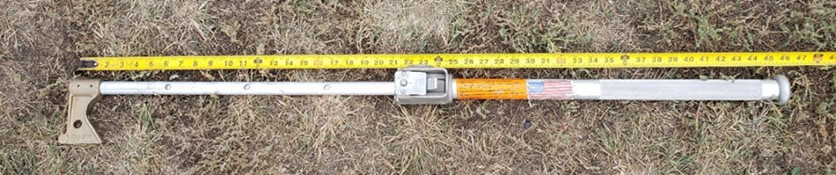

The limited-scope assessment did not formally assess the effectiveness of a brake stick to apply hand brakes; however, anecdotal observations indicate that such a device could greatly increase efficiency (i.e., reduce time and effort) of the task with a potential doubling of torque input.
Conclusions from the study
It would not have been possible for the average participant in this study to have secured the occurrence train on the mountain grade using hand brakes alone given the design and condition of the equipment provided.
Based on the average input torque of 55 foot-pounds seen in this study, between 116 and 162 hand brakes, depending on the COF of the brake shoes, would have been required to hold the 112-car occurrence train on the 2.2% grade.
Instead of setting retainers, applying 84 hand brakes at the average input torque of 55 foot-pounds would not have secured the train with the air brakes released, but would have slowed its descent rate.
The current hand brake design would require an input torque of 75 to 103 foot-pounds, depending on the COF of the brake shoes, for the occurrence train if 84 hand brakes had been applied. This input torque is higher than what the average participant could provide during the testing.
Appendix F – Association of American Railroads Circular Letter C-12027 and New York Air Brake General Letter GL-490


Appendix G - Canadian Pacific bulletin CPSB048-13
Appendix H – TSB investigations involving crew resource management at railway companies
R17W0267 – On 22 December 2017, a Canadian National Railway Company (CN) foreman and a helper were performing switching operations at CN’s Melville Yard in Melville, Saskatchewan. The foreman was operating extra yard assignment Y1XS-01 using a remote control locomotive system (RCLS) when the foreman became pinned between the assignment and the lead car of an uncontrolled movement while applying a hand brake. The foreman received fatal injuries. There was no derailment and no dangerous goods were involved. In this occurrence, although the foreman and helper held 2 job briefings, several elements of the plan were not effectively communicated and/or coordinated. If crew members do not receive enhanced crew resource management training to develop skills in crew coordination and communication, there is an increased risk that inadequate crew communication will lead to unsafe operations.
R16E0051 – On 04 June 2016, CN train 112 was proceeding eastward on the Edson Subdivision when it collided at 18 mph with the tail end of CN train 302, which was stopped near Carvel, Alberta. No cars derailed as a result of the collision. There was minor damage to 1 empty hopper car on train 302. The investigation determined that the conductor, who was also a qualified locomotive engineer (LE) but with less experience than the occurrence LE, did not initially question the LE on the speed of the train while operating past the restricting signal.Footnote 216 In addition, the conductor did not further question the LE after it was decided not to report the collision. If operating employees are not trained in crew resource management, including how to make decisions when authority gradients are present, crew coordination and interaction may not be effective, increasing the risk of human factors–related accidents.
R07E0129 – On 27 October 2007, westbound CN train 417 was unable to stop prior to passing a stop signal near Peers, Alberta, on the Edson Subdivision and collided with eastbound CN train 342, which was entering the siding. Train 417’s locomotives and 22 cars derailed. Five cars on train 342 derailed. The investigation determined that the conductor had deferred to the LE’s experience and did not challenge his actions. It was also stated that, in the absence of procedures that recognize the risks inherent in an authority gradient, intra-cab communication can fail.
R98V0148 – On 11 August 1998, CP train 463 collided with the rear end of CP train 839 at Mile 78.0 of the Shuswap Subdivision, near Notch Hill, British Columbia. One car on train 463 and 2 cars on train 839 derailed. The investigation determined that neither the conductor nor the LE challenged each other’s identification of signals; the authority gradient between the 2 crew members probably prevented the conductor from challenging the LE and expressing his concerns.
R96Q0050 – On 14 July 1996, Quebec North Shore and Labrador Railway (QNS&L) train FCS 45 collided with the tail end of stationary QNS&L train PH-475 at Mile 131.68 of the Wacouna Subdivision near Mai, Quebec. The last 3 cars of the stationary train derailed. The locomotive of the moving train was extensively damaged. The LE of the moving train sustained minor injuries. The investigation determined that at the time, there was no established crew resource management program in use on the railway that would ensure that all persons involved were aware of the most up-to-date, accurate information concerning the movement of trains and engines.
Appendix I − TSB investigations related to hazard identification, data trend analysis, and risk assessments at Canadian Pacific
R19C0002 – On 06 January 2019, at approximately 0655 Mountain Standard Time, the crew of Canadian Pacific Railway Company (CP) yard assignment CW11-06 was switching cars eastward into the classification tracks at Alyth C-Yard in Calgary, Alberta, when 56 cars disconnected from the movement and ran uncontrolled down the lead track into the designated emergency track, contacting a cut of stationary loaded hopper cars. As a result of the collision, a total of 22 cars derailed.
Alyth C-Yard, which had previously been used as a hump yard, was deactivated in 2013 and re-opened on 22 December 2018 as a flat switching yard. Although a risk assessment had been performed in anticipation of the operational change, a series of uncontrolled movements occurred in the first 16 days of operation, indicating that either some of the hazards that existed were not identified, or the applied risk mitigation strategies were inadequate. When an operational change takes place and the preceding risk assessment does not identify certain hazards, the associated risks may not be adequately mitigated, resulting in an increased potential for accidents.
R18H0039 – On 14 April 2018, at about 0215 Eastern Daylight Time, a CP yard foreman and a CP yard helper were performing switching operations at CP’s Toronto Yard in Toronto, Ontario, using a remote control locomotive system (RCLS). The yard foreman was operating yard assignment T16-13 when it began to roll uncontrolled eastward on the Staines connecting track. There was no derailment or collision, and there were no injuries.
Because the majority of switching was taking place at the west end of the yard, the installation of derails was recommended for the west end of the yard to protect the main track from uncontrolled movements. When CP increased the amount of yard shifts working at any given time to 2 in February 2018, the second yard shift worked primarily at the east end of the yard. CP did not consider the addition of yard crews as a change to its operations, even though the second crew would be working primarily in the east end of the yard where no derails were installed. Consequently, a new risk assessment was not performed. Therefore, the opportunity to identify new hazards caused by the addition of the second crew working on the east end of the yard was missed.
R17D0123 – On 08 November 2017, CP yard assignment FS23 was performing switching operations in St-Luc Yard at Mile 46.9 of the CP Adirondack Subdivision, in Montréal, Quebec. At about 0600 Eastern Standard Time, while reversing southward in the dark at approximately 10 mph, the yard assignment struck and fatally injured the yard helper.
When the classification yard was closed in 2012, most of the switching operations at St-Luc Yard were moved to a section of the yard referred to as the “diamond” area, which had a significantly different configuration than the classification yard. Given the differences between the configuration of the classification yard and the diamond area, a task analysis of the yard helper and yard foreman roles for the diamond area would have been appropriate.
A task analysis could have identified the differences between the release zones, the risk of being foul of the tracks when releasing cars or turning switches, the presence of tripping hazards, and a reduction in the level of ambient lighting. Thus, mitigating measures such as increased lighting, improved walking conditions, the identification of switches and their targets, and the modification of the switching leads and release zones could have been identified, reducing the risks to employees becoming foul of a track while performing switching operations.
Because CP did not consider the closing of the St-Luc classification yard to be a significant change to railway operations at St-Luc, no risk assessment was performed in 2012. Therefore, the opportunity to identify new hazards created by the change to switching at St‑Luc Yard was missed.
R16C0065 – On 03 September 2016, at about 0925 Mountain Daylight Time, CP train 303‑646, proceeding westward at approximately 22 mph at Mile 171.7 of the Brooks Subdivision, collided with the tail end of train 113-31, which was stopped on Track PT01, near Alyth Yard in Calgary, Alberta. Two locomotives on the head end of train 303-646 derailed, as did 2 covered hopper cars behind the locomotives. The last car on train 113‑31, a 3‑platform container car, also derailed. There were no injuries. No dangerous goods were released.
In June 2013, following the collapse of the Bonnybrook Bridge, CP had changed the designation of Track PT01 between Ogden and the begin/end interlocking limits at 12th Street East from main-track centralized traffic control (CTC) to non-main track. However, when rail traffic over the bridge resumed, CP did not put CTC back in service at this location. When it was decided to keep this section of track designated as non-main track, no risk assessment was conducted, nor was one required at that time.
Without a risk assessment, the railway was not specifically aware of the hazards and safety concerns of train crews when operating through this location. Therefore, no specific action had been taken by the railway to mitigate the potential hazards. The investigation determined that, if risk assessments are not conducted for changes to railway operations, potential hazards associated with the operational change may not be identified and appropriately mitigated, increasing the risk of accidents.
R16W0074 – On 27 March 2016, at about 0235 Central Standard Time, while switching in Sutherland Yard in Saskatoon, Saskatchewan, CP 2300 remote control locomotive system training yard assignment was shoving a cut of cars into Track F6. As the assignment was brought to a stop, empty covered hopper car EFCX 604991 uncoupled from the train, unnoticed by the crew. The car rolled uncontrolled through the yard and onto the main track within cautionary limits of the Sutherland Subdivision. The car travelled about 1 mile and over 2 public automated crossings before coming to a stop on its own. There were no injuries and no derailment. No dangerous goods were involved.
In early 2016, several operational changes were implemented by CP at Sutherland Yard. The operational changes prompted CP to complete a combined risk assessment in accordance with the Railway Safety Management System Regulations, 2015.
While the risk assessment covered RCLS operations and the introduction of a point protection zone, it did not consider the impact of reducing the number of train crews or the change in local practice to primarily switching without air. It also did not specifically identify potential hazards related to crew inexperience or an uncontrolled movement. Therefore, remedial action to address a potential uncontrolled movement, such as the installation of a derail, was not considered or implemented to protect against uncontrolled movements while switching without air.
R16H0024 – On 06 March 2016, at approximately 1540 Eastern Standard Time, CP freight train 100-03 was proceeding eastward at about 35 mph when it collided with a stationary hi-rail vehicle at Mile 118.36. The foreman and machine operator had exited the hi-rail vehicle just before the collision.
As part of its SMS, CP collects and analyses safety data to identify emerging trends, including recurring situations where safety is compromised. In this occurrence, there was no indication that CP had specifically identified the upward trend of track units being operated outside their limits of authority, although CP had initiated work on its Employee in Charge system (a system designed to mitigate safety risks during track unit operation). If railway safety data are not regularly reviewed to identify trends, emerging trends or recurring situations, and appropriate action is not taken, safety risks may remain unidentified and unmitigated, increasing the risk of accidents.
Appendix J – Golder Associates audit of Canadian Pacific’s safety management system (CP internal audit)
Under sections 30, 31, and 32 of the Railway Safety Management System Regulations, 2015, railway companies must conduct an audit of their safety management system (SMS) every 3 years and produce a safety action plan to address identified deficiencies.
In 2017, Canadian Pacific Railway Company (CP) contracted Golder Associates Limited to audit its SMS, and Golder delivered its findings on 17 July 2017. Golder categorized its findings as major non-conformances (MA), minor non-conformances (MI) and opportunities for improvement (OFI). The findings were also assessed for urgency using the following classification:
- High Priority (HI) A high-priority finding is one that meets one or more of the following criteria:
- Presents an imminent or escalating risk of significant health, safety, regulatory or reputational impact;
- Is potentially non-compliant with a regulatory requirement;
- Requires an unusual or significant allocation of effort, capital works, resources and / or time to rectify;
- Must be addressed on a priority basis to enable the basic functioning of other elements of the SMS.
- Moderate Priority (MO) A moderate-priority finding is one that meets one or more of the following criteria:
- Will not result in significant health, safety, regulatory or reputational impact;
- Can be corrected over time without risk of escalation or increasing severity;
- Can be corrected within the usual Continual Improvement cycle of the SMS (e.g.: in an Annual Management Review process).
- Low Priority (LO) A low-priority finding is one that meets one or more of the following criteria:
- Has no directly associated risk of health, safety, regulatory or reputational impact;
- Does not impede the functionality of any other element of the SMS; and
- Can be corrected within the effort required for the regular ongoing maintenance of the SMS.Footnote 217
Tables J1 and J2 present some of the findings and opportunities for improvement identified by this audit that are relevant to this occurrence.
| Finding No. | Priority | Finding statement |
|---|---|---|
| MI-12-1 | MO | There appears to be an inconsistent level of investigation and analysis into incidents, including railway occurrences. |
| MI-12-1 | MO | The effectiveness of workplace and safety committee inspections in some areas is not sufficient to verify or maintain compliance with legal requirements. |
| MI-13-2 | MO | Variability in the current practices for safety hazard reporting results in an incomplete or biased data set for trend analysis of safety concerns. |
| MI-13-3 | MO | Information from safety committee inspections and locally-managed Safety Hazard Reports is not evaluated for system-wide trends and safety concerns. |
| MI-24-1 | MO | Reporting tools described in the reporting procedures are not well known and/or inconsistently used. |
| MI-26-1 | MO | Some instances of lapsed mandatory refresher training requirements were reported. |
| MI-27-1 | MO | Version control verification measures are lacking for some key operational safety documents. |
| MI-9-1 | LO | Out-of-date safety policy posters were posted on bulletin boards and elsewhere in the workplace at Toronto and Coquitlam yards. |
| MI-20-1 | LO | It is not clear how the current process for evaluating the effectiveness of remedial action involves the bargaining units. |
| MI-25-1 | LO | Employees involved in activities that may affect railway safety do not always have appropriate training. |
| MI-29-1 | LO | SMS procedure documents should be reviewed to ensure that the next scheduled review dates are accurate. |
| Finding No. | Priority | Finding statement |
|---|---|---|
| OFI-12-1 | MO | Incident reports contained in the Incident Manager (IM) system do not include the information reported to the TSB during the initial report. |
| OFI-12-2 | MO | The Initial Incident Report form is not referenced in the CP procedure with respect to incident reporting. |
| OFI-12-3 | MO | There are inconsistencies in CP procedures and TSB Regulations with respect to definition of a railway occurrence. |
| OFI-13-1 | MO | Job aids that are used to help identify and control operational/occupational safety risks are not always complete. |
| OFI-13-2 | MO | Communication back to employees who have raised concerns is not always conducted in a prompt or effective manner. |
| OFI-13-3 | MO | There is an opportunity to further enhance operational safety information sharing between CP and its contractors. |
| OFI-13-4 | MO | There is an opportunity to enhance the information management tools, consistent with the operational criticality of the data. |
| OFI-15-1 | MO | There is an opportunity to conduct additional risk assessments where they could provide value or update understandings of relevant risk mitigation strategies. |
| OFI-17-1 | MO | Inconsistency was noted between risk assessments in the methods used to estimate likelihood. |
| OFI-21-1 | MO | Current targets are only measured with lagging indicators, although several leading indicators are available. |
| OFI-25-1 | MO | Instances were observed of a lack of clarity in the presentation and understanding of safety rules and requirements. |
| OFI-25-2 | MO | The management of change process, as it relates to changes in operating procedures and instructions, is inconsistent between departments. |
| OFI-25-3 | MO | There is no consistent way to confirm and demonstrate that communications on changes to rules have been received by individual employees. |
| OFI-26-1 | MO | There is inconsistency in the performance of e-tests, with regard to the recording of results, the failure rates, and the assignment of pass / fail grades. |
| OFI-27-1 | MO | Instances of incomplete communication with workers/employees during efficiency/proficiency testing were reported. |
| OFI-27-2 | MO | Concerns were expressed regarding the competency of auditors during execution of efficiency/proficiency tests. |
| OFI-28-1 | MO | While the principles of fatigue science stipulated in the SMS Regulations are considered in the scheduling model used by CP, the model does not consider other factors that may also contribute to fatigue. |
| Occurrence number | Date | Description | Location | Cause |
|---|---|---|---|---|
| R19C0015 (this occurrence) | 2019-02-04 | Uncontrolled movement of rolling stock and main-track train derailment, Canadian Pacific Railway Company, freight train 301-349, Mile 130.6, Laggan Subdivision | Yoho, British Columbia | Loss of control |
| R18M0037 | 2018-12-04 | Employee fatality, Canadian National Railway Company, yard assignment L57211-04, Mile 1.03, Pelletier Subdivision | Edmundston, New Brunswick | Insufficient securement |
| R18Q0046 | 2018-05-01 | Non-main-track uncontrolled movement and derailment of rolling stock, Quebec North Shore and Labrador Railway, cut of cars | Sept-Îles, Quebec | Switching without air |
| R18H0039 | 2018-04-14 | Uncontrolled movement of rolling stock, Canadian Pacific Railway Company, locomotive remote control system yard assignment T16-13, Mile 195.5, Belleville Subdivision | Toronto, Ontario | Loss of control |
| R18E0007 | 2018-01-10 | Uncontrolled movement of rolling stock, Canadian National Railway Company, freight train L76951-10, Mile 0.5, Luscar Industrial Spur | Leyland, Alberta | Loss of control |
| R17W0267 | 2017-12-22 | Employee fatality, Canadian National Railway Company, extra yard assignment Y1XS-01 | Melville, Saskatchewan | Switching without air |
| R17V0096 | 2017-04-20 | Non-main-track uncontrolled movement, collision, and derailment, Englewood Railway, Western Forest Products Inc., cut of cars | Woss, British Columbia | Switching without air |
| R16W0242 | 2016-11-29 | Uncontrolled movement, collision, and derailment, Canadian Pacific Railway Company, ballast train BAL-27 and freight train 293-28, Mile 138.70, Weyburn Subdivision | Estevan, Saskatchewan | Loss of control |
| R16T0111 | 2016-06-17 | Uncontrolled movement of railway equipment, Canadian National Railway Company, remote control locomotive system 2100 west industrial yard assignment, Mile 23.9, York Subdivision, MacMillan Yard | Vaughan, Ontario | Loss of control |
| R16W0074 | 2016-03-27 | Uncontrolled movement of railway equipment, Canadian Pacific Railway Company, remote control locomotive system 2300 training yard assignment, Mile 109.7, Sutherland Subdivision | Saskatoon, Saskatchewan | Switching without air |
| R16W0059 | 2016-03-01 | Uncontrolled movement of railway equipment, Cando Rail Services, 2200 Co‑op Refinery Complex assignment, Mile 91.10, Quappelle Subdivision | Regina, Saskatchewan | Insufficient securement |
| R15D0103 | 2015-10-29 | Runaway and derailment of cars on non-main track, Canadian Pacific Railway Company, stored cut of cars, Mile 2.24, Outremont Spur | Montréal, Quebec | Insufficient securement |
| R15T0173 | 2015-07-29 | Non–main-track runaway, collision, and derailment, Canadian National Railway Company, cut of cars and train A42241‑29, Mile 0.0, Halton Subdivision | Concord, Ontario | Switching without air |
| R13D0054 | 2013-07-06 | Runaway and main-track derailment, Montreal, Maine & Atlantic Railway, freight train MMA-002, Mile 0.23, Sherbrooke Subdivision | Lac-Mégantic, Quebec | Insufficient securement |
| R12E0004 | 2012-01-18 | Main-track collision, Canadian National Railway Company, runaway rolling stock and train A45951-16, Mile 44.5, Grande Cache Subdivision | Hanlon, Alberta | Insufficient securement |
| R11Q0056 | 2011-12-11 | Runaway train, Quebec North Shore and Labrador Railway, freight train LIM-55, Mile 67.20, Wacouna Subdivision | Dorée, Quebec | Loss of control |
| R09D0053 | 2009-09-09 | Non–main-track collision, VIA Rail Canada Inc., locomotive 6425, Montréal Maintenance Centre | Montréal, Quebec | Switching without air |
| R09T0057 | 2009-02-11 | Runaway and non–main-track train derailment, Southern Ontario Railway, 0900 Hagersville Switcher, Mile 0.10 and Mile 1.9 of the Hydro Spur | Nanticoke, Ontario | Insufficient securement |
| R08V0270 | 2008-12-29 | Non–main-track train runaway and collision, Kettle Falls International Railway, Waneta Turn Assignment, Mile 141.20, Kettle Falls Subdivision | Waneta, British Columbia | Loss of control |
| R07H0015 | 2007-07-04 | Runaway rolling stock, Canadian Pacific Railway Company, runaway cut of cars, Mile 119.5, Winchester Subdivision | Smiths Falls, Ontario | Insufficient securement |
| R07V0109 | 2007-04-23 | Non-main-track train derailment, Kootenay Valley Railway, 0700 Trail yard assignment, Mile 19.0, Rossland Subdivision | Trail, British Columbia | Loss of control |
| R06V0183 | 2006-09-03 | Runaway and derailment, White Pass and Yukon Railway, work train 114, Mile 36.5, Canadian Subdivision | Log Cabin, British Columbia | Loss of control |
| R06V0136 | 2006-06-29 | Runaway and derailment, Canadian National Railway Company, freight train L-567-51-29, Mile 184.8, Lillooet Subdivision | Lillooet, British Columbia | Loss of control |
| R05H0011 | 2005-05-02 | Runaway and main-track train collision, Ottawa Central Railway, freight train 441, Mile 34.69, Alexandria Subdivision | Maxville, Ontario | Insufficient securement |
| R04V0100 | 2004-07-08 | Uncontrolled movement of railway rolling stock, Canadian National Railway Company, train M-359-51-07, Mile 57.7, Fraser Subdivision | Bend, British Columbia | Loss of control |
| R03T0026 | 2003-01-21 | Yard collision, Canadian Pacific Railway Company, car HOKX 111044, Mile 197.0, Belleville Subdivision, Toronto Yard | Agincourt, Ontario | Switching without air |
| R03T0047 | 2003-01-22 | Yard collision, Canadian National Railway Company, tank car PROX 77811, Mile 25.0, York Subdivision | Toronto, Ontario | Switching without air |
| R99D0159 | 1999-08-27 | Runaway cars, Canadian National Railway Company, Mile 69.4, Kingston Subdivision, Wesco Spur | Cornwall, Ontario | Insufficient securement |
| R98M0029 | 1998-09-24 | Main-track runaway, collision, and derailment, Matapédia Railway, Canadian National Railway Company train A402-21-24, Mile 105.4, Mont-Joli Subdivision | Mont-Joli, Quebec | Insufficient securement |
| R98M0020 | 1998-07-31 | Main-track runaway and collision, VIA Rail Canada Inc., passenger train 14 and uncontrolled five-pak movement, Mile 105.7, Matapédia Railway Mont-Joli Subdivision | Mont-Joli, Quebec | Insufficient securement |
| R97C0147 | 1997-12-02 | Runaway and derailment, Canadian Pacific Railway Company, train 353-946, Laggan Subdivision | Field, British Columbia | Loss of control |
| R96C0172 | 1996-08-12 | Main-track collision, Canadian National Railway Company, train 117 and uncontrolled movement of 20 cars, Mile 122.9, Edson Subdivision | Near Edson, Alberta | Insufficient securement |
| R96C0209 | 1996-10-09 | Runaway cars, Canadian Pacific Railway Company, CP 0700 yard assignment, Mile 166.2, Willingdon Subdivision, Clover Bar exchange track | Edmonton, Alberta | Insufficient securement |
| R96T0137 | 1996-04-24 | Runaway of 5 tank cars, Canadian National Railway Company, Mile 0.0, Hagersville Subdivision | Nanticoke, Ontario | Insufficient securement |
| R96C0086 | 1996-04-13 | Runaway train, Canadian Pacific Railway Company, freight train 607-042, Mile 133.0, Laggan Subdivision | Field, British Columbia | Loss of control |
| R95M0072 | 1995-12-14 | Runaway cars, Canadian National Railway Company, train 130-13, Mile 0.0, Pelletier Subdivision | Edmundston, New Brunswick | Insufficient securement |
| R94V0006 | 1994-01-18 | Runaway train, Canadian National Railway Company, freight train 459-GP-18, Mile 175, Grande Cache Subdivision | Latornell, Alberta | Loss of control |
Glossary
- AAR
- Association of American Railroads (United States)
- AFM
- air flow meter
- APB
- automatic parking brake
- ASCT
- automated single car test
- ATBE
- automated train brake effectiveness
- BCM
- brake cylinder maintaining
- BCP
- brake cylinder pressure
- BHP
- brake horsepower
- BPP
- brake pipe pressure
- CCFHSC
- Calgary Cross-Functional Health and Safety Committee
- CCV
- car control valve
- CFM
- cubic feet per minute
- CN
- Canadian National Railway Company
- COT&S
- “clean, oil, test & stencil”
- CP
- Canadian Pacific Railway Company
- CRM
- crew resource management
- CROR
- Canadian Rail Operating Rules
- DB
- dynamic brake
- DP
- distributed power
- ECP system
- electronically controlled pneumatic system
- EQS Regulations
- Railway Employee Qualification Standards Regulations
- ER
- equalizing reservoir
- FHOP
- Field Hill operating procedures
- GBO
- General Bulletin Order
- GOI
- General Operating Instructions
- HP
- high pressure
- LE
- locomotive engineer
- LER
- locomotive event recorder
- mph
- miles per hour
- NRC
- National Research Council of Canada
- NYAB
- New York Air Brake
- OEM ID tag
- original equipment manufacturer’s identification tag
- OFI
- opportunity for improvement
- PNR
- Prairie and Northern Region
- psi
- pounds per square inch
- QSLV
- quick service limiting valve
- RSA
- Railway Safety Act
- RSI
- railway safety inspector
- RTC
- rail traffic controller
- SCT
- single car test
- SD
- standard deviation
- SI
- special instruction
- SMS
- safety management system
- SMS Regulations
- Railway Safety Management System Regulations, 2015
- TC
- Transport Canada
- TSB
- Transportation Safety Board of Canada
- WTD
- wheel temperature detector