
Rail transportation safety investigation report R19T0107
Main-track train derailment
Canadian National Railway Company
Freight train M38331-27
Mile 60.55, Strathroy Subdivision
Sarnia, Ontario
The Transportation Safety Board of Canada (TSB) investigated this occurrence for the purpose of advancing transportation safety. It is not the function of the Board to assign fault or determine civil or criminal liability. This report is not created for use in the context of legal, disciplinary or other proceedings. See Ownership and use of content.
-
Table of contents
Executive summary
On 28 June 2019, Canadian National Railway Company (CN) freight train M38331-27 was proceeding through the CN Paul M. Tellier Tunnel en route to Port Huron, Michigan, in the United States (U.S.) when a train-initiated emergency brake applicationFootnote 1 occurred. A total of 46 rolling stock derailed in the tunnel, including a dangerous goods tank car that was breached during the derailment and released an estimated 12 000 U.S. gallons of sulphuric acid (UN1830, Class 8, Packing Group II). There were no injuries.
The accident
The westbound train had departed from Sarnia, Ontario, Canada (Mile 57.2 on the CN Strathroy Subdivision) on 28 June 2019, at about 0402 Eastern Daylight Time. The train was composed of 2 head-end locomotives and 1 mid-train distributed power remote locomotive, hauling a total of 140 freight cars. It was 9541 feet long and weighed 15 674 tons.
A train-initiated emergency brake application occurred at about 0420, while the train was travelling at 44 mph in the tunnel. The separated head-end portion of the train stopped outside the tunnel at Mile 61.46, while the tail-end portion stopped outside the tunnel’s east portal in Sarnia. A total of 45 freight cars and the distributed power remote locomotive had derailed and came to rest on both sides of the international border inside the tunnel.
The investigation determined that the accident occurred when bathtub gondola car DJJX 30478, loaded with scrap steel, sustained a structural failure and the A-end left side of the car collapsed, causing the car to derail in the tunnel on the Canadian side of the border. As car DJJX 30478 collapsed, the A-end truck became skewed beneath the car, causing both rails to roll outward and derail the trailing cars.
Structural defects that were present in the shear plates, stub sills, car body bolsters, and side sills, as well as thinned out steel sections due to corrosion of car DJJX 30478, negatively affected the ability of the car to withstand in-train forces. Bathtub gondola car DJJX 30478, built by Berwick Forge & Fabricating Corporation (Berwick Forge) in 1978, was used in a demanding service (i.e. scrap steel) for which the car was not originally designed, and there was no industry or regulatory requirement to periodically conduct a full inspection of the car to ensure it maintained its structural integrity. As a result, its structural integrity deteriorated and this was not identified prior to the accident.
As part of the investigation, analysis was conducted using train dynamics simulations and finite element modelling (FEM). The train dynamics simulations determined that in-train buff (compressive) forces of up to approximately 388 kips (388 000 pounds of force) were exerted on car DJJX 30478 while the car was in the tunnel. FEM failure analysis confirmed that, given the presence of the defects that compromised the structural integrity of car, the in-train buff forces exerted on the car resulted in the A-end structural failure that led to the derailment sequence. The maximum calculated buff force exerted on the car at the time of collapse represented a 61% reduction in the original design strength of the car due to its deteriorated condition.
Regulatory requirements for freight car inspection and safety
Rolling stock is routinely transferred at line points from one railway to another, a process referred to as interchange. Interchange occurs when a railway accepts a freight car for service on its line from another railway at line points or when crossing the Canada/U.S. border.
The Transport Canada (TC)-approved Railway Freight Car Inspection and Safety Rules (2014) (freight car safety rules) and the U.S. Federal Railroad Administration Code of Federal Regulations, Title 49, Volume 4, Part 215—Railroad Freight Car Safety Standards (2011) (freight car safety standards) establish the minimum safety criteria that apply to freight cars operated by federally regulated railway companies in each respective country. Freight cars that travel within Canada or the U.S. must comply with these minimum criteria, though both have provisions that permit freight cars with defects to be moved to a location for repair.
However, neither the Canadian freight car safety rules nor the U.S. freight car safety standards contain limits for damage to significant freight car structure, such as buckled side posts; ruptured side sheets, end sheets, and tub sections; negative side sill camber; buckled top chords; or extensive cracking and corrosion. Thus, the structural defects did not prohibit car DJJX 30478 from being interchanged.
Interchange of bathtub gondola car DJJX 30478
The bathtub gondola car that failed in the tunnel was in utility coal service for about 34 years. The Association of American Railroads (AAR) had qualified the car for “extended service,” which applies to freight cars built new since 01 July 1974. Being qualified for extended service permits the car to operate for up to 50 years from the original manufacturing date without the need to re-qualify the car, unless otherwise noted.
In 2012, the car was retired from coal service and purchased by the David J. Joseph Company Rail Equipment Group (DJJ Co.), as part of a larger purchase of 1650 similar cars, with the intention of using them in scrap steel service. DJJ Co. modified all 1650 cars by replacing the 4 reinforcement crossbars that obstructed top loading of scrap steel with 2 large steel u-channels fabricated inside the car to compensate for the structural change to reinforce the tub. The modifications for all 1650 cars were approved by the AAR.
At the time of its failure in the tunnel, bathtub gondola car DJJX 30478 was in a deteriorated condition and had a number of pre-existing defects that contributed to its reduced structural integrity. Visual examination of the car following the accident determined that the defects were not recent and would have developed over a period of time prior to the accident.
Despite its deteriorated condition, car DJJX 30478 travelled frequently within, and between, Canada and the U.S. and was interchanged between railways 16 times in the 6 months preceding the accident.
In the 3 months preceding the accident, car DJJX 30478 received 24 certified car inspections conducted at various CN line points, had numerous pull-by inspections, and traversed multiple wayside inspection systems, with no significant defects noted. In the year prior to the accident, the car only was only subject to routine maintenance.
National Research Council Canada compressive end-load testing of DJJX bathtub gondola cars
The Transportation Safety Board of Canada (TSB) contracted the National Research Council Canada to perform compressive end-load testing of 3 similar bathtub gondola cars to car DJJX 30478 that were present in the head-end portion of the train. The testing assessed the ability of these cars to withstand 3 consecutive applications of 1000 kips of longitudinal compressive force in their current worn state after 40 years of service. The tests were performed in accordance with the AAR Manual of Standards and Recommended Practices criteria for the design and construction of new freight cars.
Two of the tested cars that had been built by ACF Industries Inc. had thicker underframe steel members and each survived 3 consecutive applications of 1000 kips. The third car, a Berwick Forge car (DJJX 30156), which was the same design and vintage as car DJJX 30478, experienced structural failure at about 628 kips under testing during the first force application. As a result, the test could not be repeated.
Safety action taken
Transportation Safety Board of Canada
Following this accident, the TSB communicated critical safety informationFootnote 2 on
- railway emergency procedures for conducting train inspections following a derailment in a tunnel when dangerous goods are involved (TSB Rail Safety Advisory [RSA] 08/19, issued on 19 August 2019);
- railway and car owner procedures to identify, inspect, and repair bathtub gondola cars that are equipped with stub sills, and which were constructed in the late 1970s and early 1980s (TSB RSA 09/19, issued on 16 September 2019);
- managing in-train forces (TSB RSA 06/20, issued on 11 September 2020); and
- structural issues identified on bathtub gondola cars built by Berwick Forge & Fabricating Corporation (TSB RSA 07/20, issued on 11 September 2020).
Transport Canada
In response to TSB RSA 08/19, TC wrote to the Railway Association of Canada and the Western Canadian Short Line Railway Association recommending that Canadian railways ensure that their equipment, procedures, and instructions be reviewed and updated, as required, to ensure employee safety.
In response to TSB RSAs 09/19 and 07/20, TC contacted the AAR regarding the issues mentioned in the 2 RSAs and continued to follow up with the AAR to ensure that all of the cars identified in the AAR-issued Maintenance Advisory MA-0188 were inspected.
Canadian National Railway Company
Following the derailment, CN inspected 416 of the 2130 identified cars of similar type and vintage to the occurrence bathtub gondola car and that were being used in scrap iron and steel service in North America. CN identified defects in 149 of the 416 cars (36%).
In response to TSB RSA 08/19, CN issued the Rule 83(c) Summary Bulletin Nov 2020 – April 2021, which included new tunnel emergency procedures that must be followed in the event of an emergency in the tunnel.
Association of American Railroads
The AAR issued maintenance advisories MA-0188 and MA-0198, Early Warning EW-5344 and Equipment Instruction El-0017 to the rail industry requiring the inspection of specified bathtub gondola cars. Equipment Instruction El‑0017, which was issued subsequent to the maintenance advisories and early warning, requires Berwick Forge bathtub gondola cars of the same vintage as the occurrence car to be inspected every 2 years. Cars identified in the equipment instruction are automatically prohibited from interchange under the AAR Interchange Rules unless they have been inspected within the 2-year timeframe and determined to be free from specified defects. The process will repeat every 2 years for each car on the list.
The 2020 AAR Interchange Rules governing centre sills, draft sills, coupler carriers, and side sills were revised to include causes for attention related to stub sills and side sills defects.
1.0 Factual information
On 27 June 2019, at about 1530 Eastern Daylight Time,Footnote 3 westbound Canadian National Railway Company (CN) freight train M38331-27 had received a certified car inspection (CCI) and a No. 1 air brake testFootnote 4 at CN MacMillan Yard, located near Toronto, Ontario (Canada), with no defects noted. The train consisted of 2 head-end locomotives (CN 2233 and CN 8857) and 1 mid-train distributed power (DP) remote locomotive (CN 8832), situated between the 81st and 82nd cars (line 81Footnote 5 and line 82). It was hauling a total of 117 freight cars that included 85 loaded cars and 32 empty cars, 14 of which were tank cars that contained the residue of dangerous goods (DG). A total of 36 cars were located behind the DP remote locomotive (line 82 to line 117). The train was 7620 feet long and weighed 11 698 tons.
At approximately 1705, the train departed MacMillan Yard, destined for Walbridge, Ohio, United States (U.S.), through Flint, Michigan, U.S. After departing MacMillan Yard, the train travelled on the CN Halton, Oakville, Dundas, and Strathroy subdivisions to Sarnia, Ontario (Canada) (Figure 1).

En route to Sarnia, the train passed a number of CN wayside inspection systems and was inspected by 20 hot bearing detectors/dragging equipment detectors and 1 wheel impact load detector, with no defects noted.
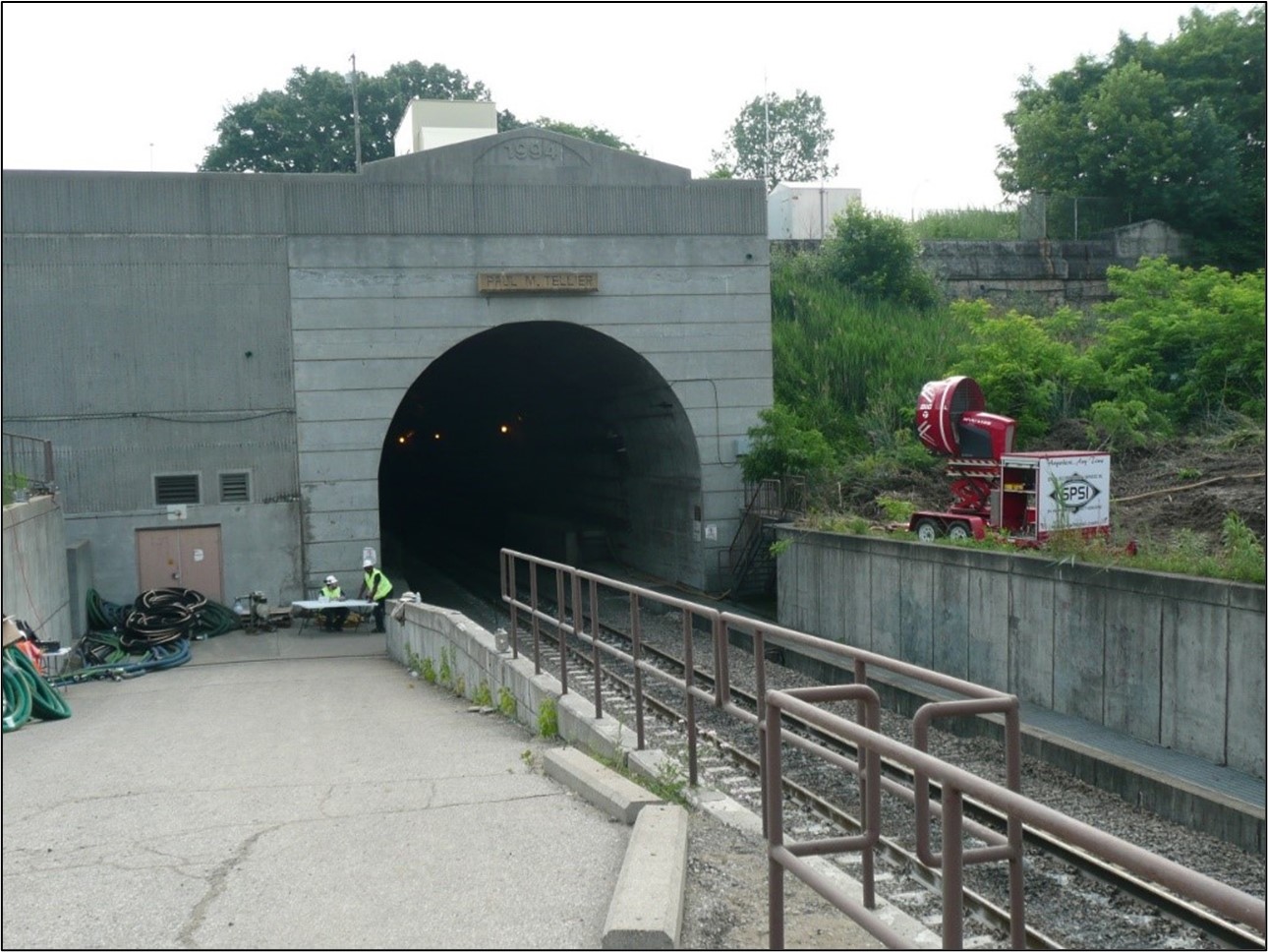
At about 0155 on 28 June 2019, the train arrived at Sarnia Yard, located at Mile 52.7 of the Strathroy Subdivision. At Sarnia, an outbound 3-person train crew, consisting of a locomotive engineer (LE), a conductor, and an assistant conductor, took control of the train in preparation for the train’s planned journey through the CN Paul M. Tellier Tunnel under the St. Clair River. The tunnel (Figure 2) connects Sarnia to Port Huron, Michigan, U.S., and traverses the international border between Canada and the U.S. at Mile 60.63 of the CN Strathroy Subdivision. The outbound train crew were qualified for their positions, were familiar with the territory, and met fitness and rest requirements.
Before the train departed Sarnia, the tail-end 36 cars (line 82 to line 117) were removed from the train and 59 cars were added behind the DP remote locomotive, in the 82nd to the 140th positions of the train. The 59 cars that were added had received a CCI and a No. 1 air brake test at Sarnia Yard before being added to the train, with no defects noted.
After switching out 36 tail-end cars and adding 59 tail-end cars in Sarnia, the train consisted of 2 head-end locomotives and a DP remote locomotive (situated between line 81 and line 82) hauling a total of 140 freight cars. The freight cars consisted of 125 loaded cars, 21 of which were tank cars loaded with DG, and 15 empty cars, 3 of which were residue DG tank cars. The train was 9541 feet long and weighed 15 674 tons.
1.1 The accident
At about 0402, the train departed from Sarnia on the Strathroy Subdivision, en route to Port Huron. Upon departure from Sarnia, the train was a key trainFootnote 6 operating on a key route.Footnote 7
At approximately 0414, the train arrived at the east crest of the tunnel while travelling at a speed of about 11 mph with the throttle in idle. From the crest, the throttle remained in idle as the train accelerated by gravitational force along the descending grade of the tunnel until the head-end locomotives arrived at the bottom of the tunnel. Once the train was at the bottom, the LE slowly increased the throttle to notch 3 as the train commenced the ascending grade toward the tunnel’s west portal in Port Huron.
At about 0420, while the train was travelling at 44 mph in the tunnel, a train-initiated emergency brake applicationFootnote 8 occurred when the head-end locomotive was at Mile 61.19. The head end of the train stopped outside the tunnel at Mile 61.46, about 1670 feet west of the tunnel west portal in Port Huron (Figure 3). The tail end of the train stopped outside the tunnel east portal in Sarnia. At about the same time, there was an alarm on the rail traffic control display screen.

Once the head-end portion of the train came to a stop, the train crew made an emergency broadcast on the emergency radio channel, as prescribed by Rule 102 of the Canadian Rail Operating Rules (CROR), to report the emergency brake application to the rail traffic controller (RTC). They then requested that the lights and ventilation fans be turned on in the tunnel. The RTC responded that the fans would be turned on shortly. At that time, the RTC had not yet determined the nature of the alarm as he needed to open a different computer window to see the details, and he did not inform the crew about the alarm.
When the crew ended their communication with the RTC, they conducted a job briefing during which they discussed the contents of the train, including the DG tank car of sulphuric acid. Soon after the briefing, the LE and the assistant conductor remained in the locomotive cab while the conductor exited the cab with a hand-held radio in order to inspect the train, in accordance with CN’s Strathroy Subdivision Timetable No. 43 instructions and Section 7.3 of CN’s General Operating Instructions (GOI). The conductor was not equipped with any respiratory protection, nor was he required to be under these instructions.
About 5 minutes after the crew had made the emergency broadcast, the RTC contacted the LE and the assistant conductor in the locomotive cab and informed them that the toxic gas alarm in the tunnel had activated. Because the DP remote locomotive was still in the tunnel and remained operative, it was assumed that diesel engine exhaust from the DP remote locomotive was the likely source of the alarm. The RTC then asked the train crew if it mattered which direction the exhaust from the fans should blow, and the crew responded that it did not, as long as the fans were running.
Meanwhile, the conductor inspected the head-end portion of the train that had exited the Port Huron portal and did not note any defects. When the conductor arrived at the portal, he believed he could hear ventilation fans operating but noticed that the lights in the tunnel were off. Subsequently, with the west-end lights off and east-end fans exhausting westward, the conductor entered the tunnel to complete the inspection of the train.
The RTC then discussed the situation with his manager. About 10 minutes later, the RTC contacted the LE and the assistant conductor by radio, and reiterated that the toxic gas alarm in the tunnel had activated, and instructed the crew members not to enter the tunnel.
Because the conductor had already entered the tunnel, the RTC, LE, assistant conductor and a trainmaster immediately attempted to contact the conductor by radio but were unable to reach him. Subsequently, the assistant conductor exited the locomotive cab to look for the conductor. Shortly thereafter, the assistant conductor observed the conductor exit the tunnel following his train inspection.
While in the tunnel, the conductor had observed that car DJJX 19371 (line 51) had the trailing wheels derailed, while the next car, DJTX 30049 (line 52) had all wheels derailed. In the darkness of the tunnel, no other cars were visible behind this car. Consequently, this occurrence was initially reported as a train pull-apart with 2 cars derailed. However, as emergency responders and CN staff began to arrive, it became evident that a much more serious accident had occurred.
Unknown to the crew at that time, 45 freight cars and the DP remote locomotive, located between line 51 and line 98 inclusive, had derailed; line 90, line 91, and line 95 did not derail. The derailed cars had piled up and came to rest on both sides of the international border inside of the tunnel, completely blocking the tunnel. The derailed cars included DG tank car UTLX 95205 (line 68), which was loaded with 12 727 U.S. gallons (48 177 L) of 94% sulphuric acid (UN1830, Class 8, Packing Group II). During the derailment, tank car UTLX 95205 was breached and released sulphuric acid in the tunnel.
After the personnel exited the tunnel, CN’s DG emergency response team responded to the site to assess the situation. Once the DG team determined that it was safe to do so, the head-end portion of the train was disconnected between line 50 and line 51. The train’s head-end locomotives and the first 50 cars were moved to CN’s Port Huron Yard and held for subsequent inspection. There were no injuries.
1.1.1 Sulphuric acid information
The sulphuric acid that was transported in UTLX 95205 was manufactured in Oakville, Ontario. It is a corrosive liquid that can cause severe skin burns and eye damage upon contact. Personnel are advised to avoid inhaling sulphuric acid vapour, mist, or spray. Protective equipment and clothing are advised to be worn in areas of spills or leaks until cleanup has been completed. Sulphuric acid may cause an exothermicFootnote 9 reaction with water and other products.Footnote 10
1.2 Emergency and environmental response
Since the border between Canada and the U.S. is located near the middle of the tunnel and was inaccessible, it was unclear whether the initial point of derailment (POD) was on the Canadian or U.S. side of the border, so the Transportation Safety Board of Canada (TSB) notified the U.S. National Transportation Safety Board (NTSB) of the accident. Subsequently, the TSB, the NTSB, and the U.S. Federal Railroad Administration (FRA) each deployed accident investigators to the site.
Due to the release of sulphuric acid in the tunnel, the U.S. Environmental Protection Agency (EPA) assumed incident command for the U.S. operations on the U.S. side under a unified command structure involving the EPA, CN, St. Clair County, the Port Huron Fire Department, Michigan State Police, and U.S. Customs and Border Protection. This group worked collaboratively and continuously with the TSB, the NTSB, and the FRA.
The EPA also coordinated response activities with Environment and Climate Change Canada. In addition, site-specific health and safety and air quality monitoring plans were developed by the EPA in collaboration with CN. These plans were updated as the evolving situation required. Incident action plans were also developed for each 24-hour operational period, and joint progress meetings were held with all attending agencies each day at 0800 in Port Huron for the duration of the response.
On 28 June 2019, the EPA instructed CN to cease clearing operations in the tunnel from the U.S. side until the sulphuric acid release was mitigated.
The engineer who designed the tunnel attended the site to evaluate the tunnel’s structural integrity. He determined that it had not been compromised and that it was safe to proceed with work in the tunnel.
1.2.1 Mitigation of sulphuric acid release
The EPA was initially concerned that the release of sulphuric acid could cause exothermic reactions with water and other products released during the derailment.
The tunnel was built with a stainless-steel sump that had a capacity of 20 000 L (approximately 5280 U.S. gallons), which was located near the derailed sulphuric acid tank car, UTLX 95205 (line 68). The sump pumps were connected to a sanitary sewer system on the Canadian side of the tunnel. However, piping within the tunnel connecting the sump to the discharge point was damaged by the derailment, and CN shut down the sump-pump system shortly after the accident.
The released product accumulated in the sump and tunnel ballast, and there was no release to the St. Clair River. Downstream water intakes in the City of Marysville, the City of St. Clair, East China Township, and the City of Algonac had been notified of the accident. None of their water supply plants were affected.
Testing performed on 30 June 2019 determined that the sump liquid consisted of 20% to 30% sulphuric acid. Work was initiated to remove (pump out) the liquid contaminated with acid from within the tunnel. The sump continued to recharge with liquid that had previously pooled in the ballast, and pumping continued until the liquid had been removed.
CN neutralized the remaining acid spillage using agricultural lime to achieve a target pH of 4, in order to meet release standards. Ventilation was re-established on both the Canadian and U.S. sides of the tunnel, with air being discharged eastward toward the tunnel’s east portal in Canada. CN contractors conducted air monitoring in the tunnel and near the tunnel’s west portal. No exothermic chemical reactions were reported.
By 05 July 2019, about 50 000 U.S. gallons of contaminated liquid had been pumped from puddles in the sump area. The liquid was initially pumped into totes,Footnote 11 transferred to a vacuum truck, and then further transferred to frac tanksFootnote 12 and totes located at a staging area about ½ mile west of the tunnel’s west portal in Port Huron. The process was later modified to pump contaminated liquid directly into the totes and then move the totes to the staging area. EPA contractors periodically monitored the temperature of tanks and totes at the staging area and visually inspected their condition.
After all rolling stock had been removed from the tunnel on 05 July 2019, CN focused on treating and removing contaminated ballast. CN delineated contaminated ballast approximately 1500 feet east and 310 feet west of the sump. The EPA reported that sodium hydroxide was used to neutralize the acid in the ballast. The plan was to remove at least the top 4 inches of ballast after treatment and ship it offsite for disposal. CN collected concrete core samples from the tunnel floor to assess any impact from the acid release, and no impact was observed. Additionally, CN ordered a replacement sump for the tunnel, which was installed on 06 July 2019.
1.2.2 Air monitoring
CN contracted GHD Limited (GHD) to provide air monitoring and industrial hygiene support for the derailment site in the tunnel. The air was monitored for sulphuric acid, sulphur dioxide, oxygen, hydrogen sulphide, carbon monoxide, and the lower explosive limit (LEL)Footnote 13 of volatile organic compounds (VOCs), all of which could have been present during the derailment and associated response activities. GHD technicians and CN responders, equipped with real-time air-monitoring devices, accompanied TSB and NTSB investigators during all tunnel entries.
The EPA established 8 permanent perimeter air-monitoring stations (Figure 4), 2 near the tunnel’s west portal (stations 4 and 8), and 6 surrounding the site and staging areas. AreaRAEFootnote 14 or MultiRAEFootnote 15 monitors were deployed at 7 of these stations for general air monitoring. SPM FlexFootnote 16 units were also deployed at 5 of these stations to specifically monitor the air for sulphuric acid.

The EPA established site-specific action levels.Footnote 17 There were no exceedances of these action levels, and sulphuric acid was not detected by 6 perimeter monitoring stations. However, sulphuric acid was detected by the 2 stations nearest the U.S. portal, with 1 exceedance that temporarily halted work on site.
Finding: Other
The emergency response unified command structure worked well and the measures put in place to protect responders, the public and the environment, as part of emergency response and site mitigation activities, were effective.
1.3 Site examination
Various site examination and investigative activities took place over a period of 9 days from 28 June 2019 to 06 July 2019. Each day began with a joint progress meeting with the agencies that were attending at that time. The TSB and NTSB investigators worked in teams on both sides of the border, in compliance with all site safety requirements.
Clearing activities to remove all rolling stock from the tunnel were conducted from both the Canadian and U.S. sides. However, most of the cars were dragged through the tunnel to the Canadian side. Clearing activities on the U.S. side were slow and methodical, as the work was periodically halted to deal with the sulphuric acid release in the tunnel. As a result, the investigation work plans were flexible and changed as the site-mitigation activities within the tunnel evolved.
On 28 June 2019, CN responders arrived in the morning and immediately started clearing activities on the U.S. side without fully documenting the accident site. Although the tunnel was completely blocked in the area of the border (Mile 60.63), TSB investigators accessed the tunnel from each side to partially document the cars that had derailed. For the duration of the response activities, investigators accessed the tunnel along the walkway on top of either the north or south reinforcement walls that run parallel to the track through the tunnel.
It was initially believed that the POD was in Canada, so the TSB assumed the role of lead investigation agency for determining the cause of derailment until the POD was confirmed and agreed upon by the TSB, the NTSB, and the FRA.
To minimize the duplication of effort for information requests, CN provided the TSB with all requested information and further provided written approval for the TSB to share the information with the NTSB and the FRA. CN and the 3 agencies worked collaboratively, sharing resources and information as they became available.
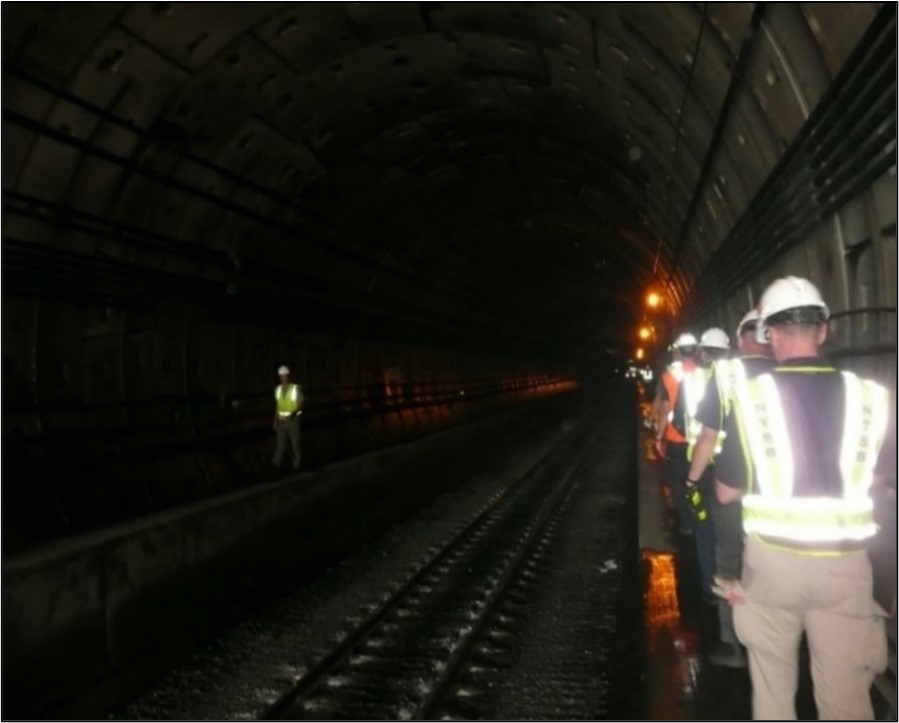
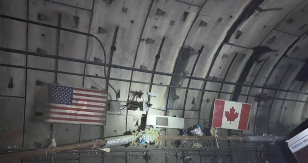
On 29 June 2019, following the joint progress meeting in Port Huron, CN personnel accompanied TSB and NTSB investigators as they entered the tunnel on the U.S. side to examine the derailed rolling stock and related damage (Figure 5).
The first derailed equipment encountered in the tunnel was the trailing end of car DJJX 19371 (line 51), a flat-bottomed gondola loaded with scrap steel.
The next car, DJTX 30049 (line 52), was also a flat-bottomed gondola loaded with scrap steel. All wheels of the car had derailed, and it came to rest at Mile 60.85. On the trailing B-endFootnote 18 of the car, the knuckle and coupler remained intact, and there was no visible impact damage. Behind (east of) car DJTX 30049 (line 52), the south rail had rolled, and there was a separation of 696 feet leading up to the leading A-end of car DJJX 30478 (line 53), a bathtub gondola car loaded with 196 300 pounds of scrap steel, at Mile 60.72.
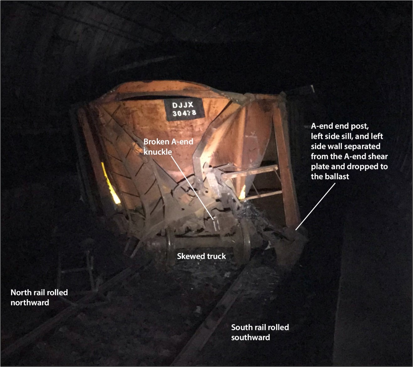
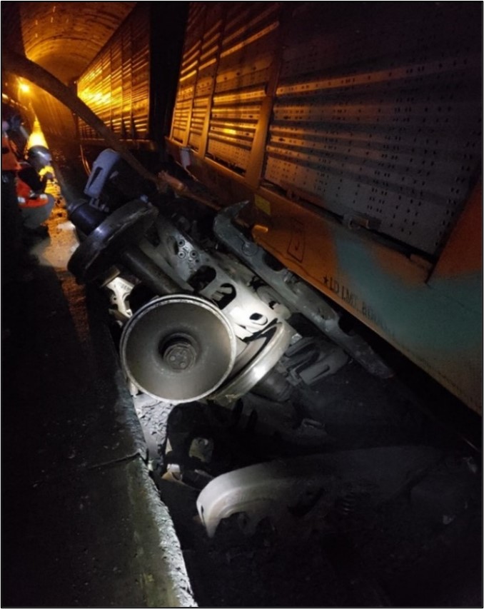
All wheels of car DJJX 30478 (line 53) had derailed, and the A-end was extensively damaged. The A-end left-side (AL) end post, side sill, and side sheet had separated from the shear plate and appeared to have collapsed. The A-end truck was skewed diagonally. The north rail had rolled northward, and the south rail had rolled southward, toward the tunnel’s reinforcement walls. The A-end knuckle was broken (Figure 6).
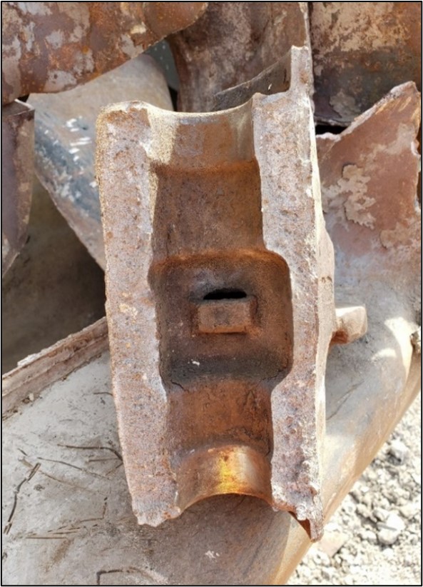
The broken A-end knuckle fracture surface on DJJX 30478 (line 53) exhibited brittle fracture characteristics with no visible defects (Figure 7). The A-end of the car also exhibited a number of pre-existing car body conditions that suggested its structural integrity may have been compromised. There were no visible impact marks on the adjacent tunnel’s reinforcement walls in this area.
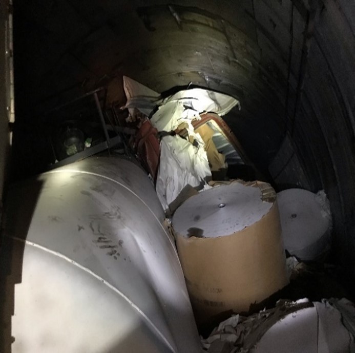
The B-end of car DJJX 30478 (line 53) was relatively intact but was surrounded by scrap steel lading from the car, which had been released to the track surface (Figure 8).

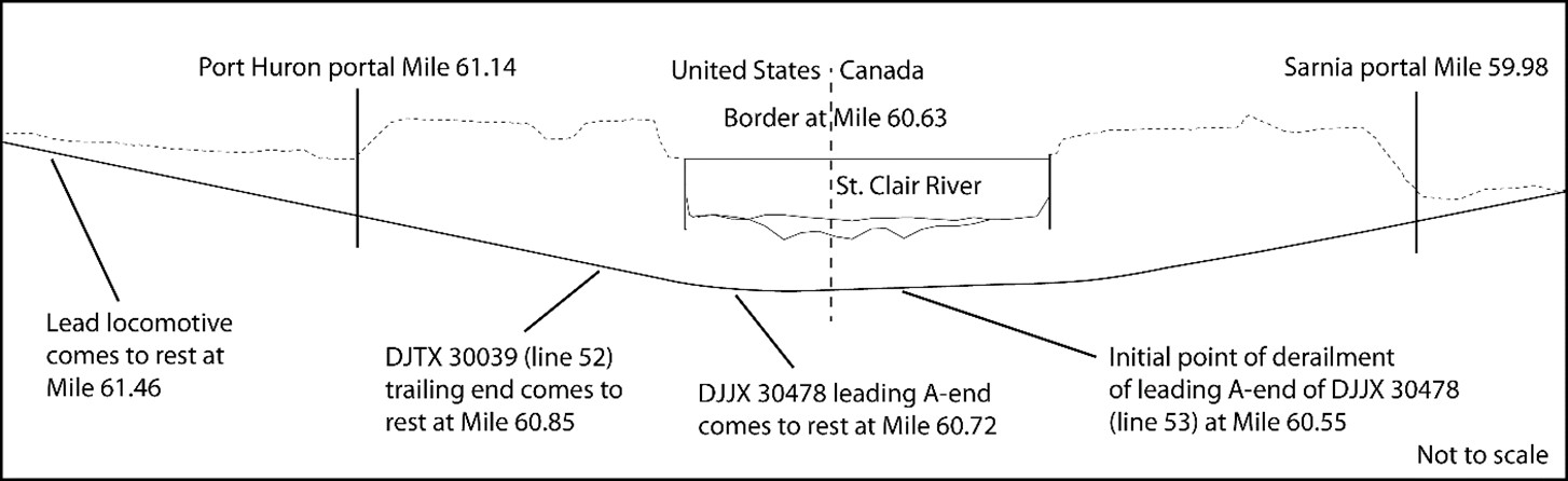
Eastward from the B-end of car DJJX 30478 (line 53), scrap steel was sporadically observed on the ballast along the south side of the tunnel, extending back to about Mile 60.55. A schematic diagram of the tunnel illustrating the initial POD and the mileage for the location of various relevant rolling stock are presented in Figure 9.
Most of the trailing cars behind car DJJX 30478 (line 53) had jackknifed and come to rest in various positions, blocking the tunnel and rendering it impassable by equipment or on foot in several locations (figures 10 and 11).

During the afternoon of 29 June 2019, CN personnel accompanied TSB and NTSB investigators as they entered the tunnel on the Canadian side and made their way along the walkway on top of the tunnel’s north reinforcement wall up to the point where the route was impassable due to the derailed cars (Figure 12).

Similar to the situation on the U.S. side, many of the derailed cars had jackknifed and came to rest between the tunnel’s reinforcement walls in various positions (Figure 13).
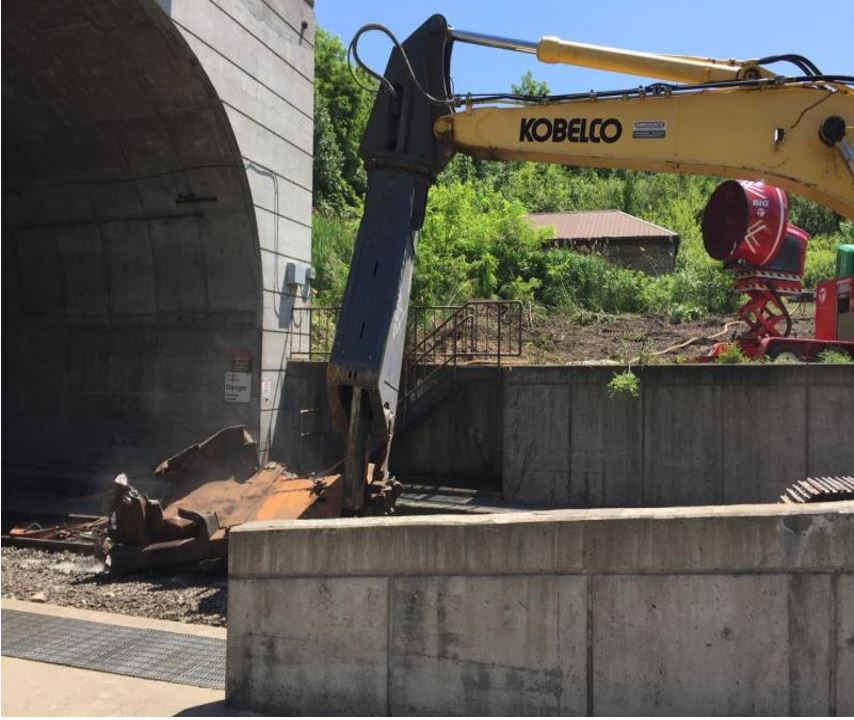
On 30 June 2019, the wreckage from bathtub gondola car DJJX 30478 (line 53), which included the A-end shear plate and stub sill, was removed from the tunnel (Figure 14).
The FRA inspected the head-end 50 cars of the train that were being held at CN’s Port Huron Yard. There were no defects observed that were condemnable under the FRA Code of Federal Regulations (CFR), Title 49, Volume 4, Part 215—Railroad Freight Car Safety Standards (2011). Therefore, the FRA had released the head-end portion of the train.
Shortly thereafter, the TSB and NTSB inspected the same 50 cars for any obvious damage that may have been related to the derailment. Although there was no damage observed, 5 bathtub gondola cars loaded with scrap steel exhibited structural conditions of interest. These cars were DJJX 950782 (line 1), DJJX 30156 (line 13), DJJX 1576 (line 47), DJJX 882062 (line 48), and DJJX 950965 (line 50). The 5 cars were removed from the train and, in addition to the wreckage from DJJX 30478 (line 53), were all held in CN’s Port Huron Yard for a more detailed examination at a later date.
On 01 July 2019, at the joint progress meeting in Port Huron, discussion centred on identifying the location where the initial emergency brake application occurred. To this point, the limited information gathered was somewhat contradictory and had yet to be validated. Validation required a detailed review of the locomotive event recorder (LER) data and DP logs recovered from the head-end locomotives and the mid-train DP remote locomotive.
The TSB, NTSB, FRA, and CN agreed that consensus was required on where the initial emergency brake application occurred, and hence the likely initial POD, in order to determine the jurisdiction of the investigation. Site examination activities continued as the recorded information was analyzed to determine whether the train-initiated emergency brake application occurred on the Canadian or the U.S. side of the border.
1.3.1 Examination of tank car UTLX 95205
Tank car UTLX 95205 (line 68) was loaded with 12 727 U.S. gallons (48 177 L) of 94% sulphuric acid. The tank car was built to tank car specification DOT-111A100W2 by ACF Industries Inc. (ACF) in March 1994, specifically for transporting sulphuric acid. The car had a gross rail load capacity of 263 000 pounds and a lading capacity of 13 739 U.S. gallons (water). The car was equipped with a 100 psi safety vent valve, a 9-inch quick-open fill hole, and a 2-inch discharge connection but was not equipped with a bottom outlet valve, head shields, jacket, or thermal protection system.
On 01 July 2019, CN contracted Exelon Corporation to conduct a confined-space aerial inspection of the wreckage using a caged drone. The inspection focused on the inaccessible freight cars in the centre of the derailment, between lines 63 and 70 (Figure 15).
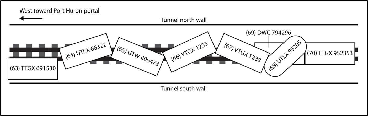
The following observations were made:
- Tank car UTLX 95205 (line 68) came to rest suspended about 4 feet above the tunnel’s north reinforcement wall.
- It was situated diagonally across the tunnel, with the leading B-end near the tunnel’s south wall, and the trailing A-end near the tunnel’s north wall.
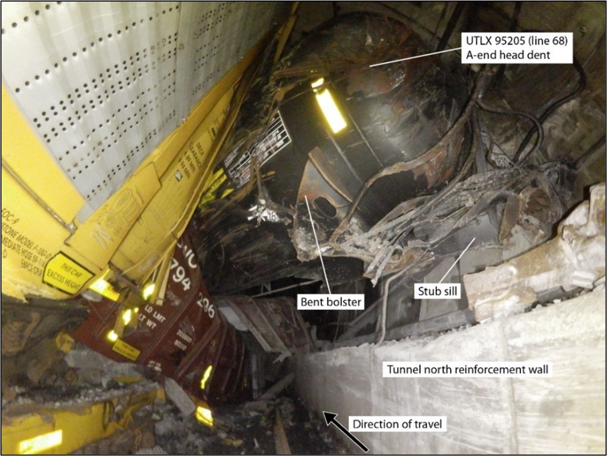
- The A-end right side of the head exhibited a large dent but no visible breaches, and the A-end right side car body bolster was bent (Figure 16).
- There was no visible damage to the top fittings, but acid residue was observed on the safety vent.
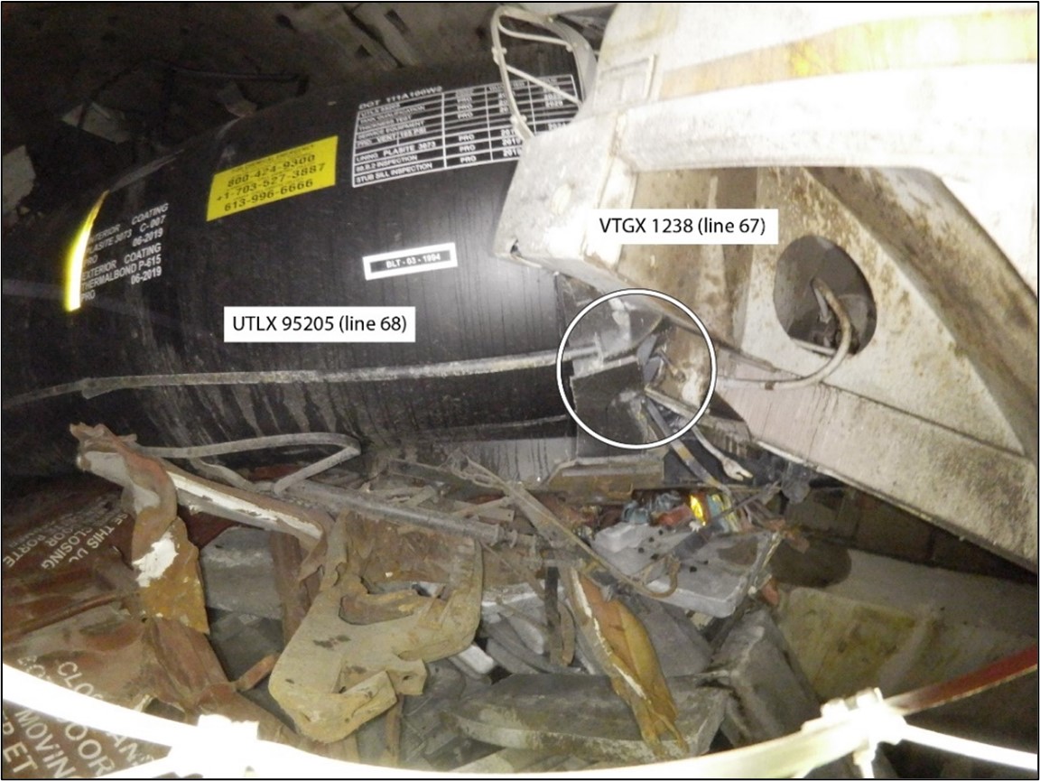
- The trailing-end stub sill and coupler of covered hopper car VTGX 1238 (line 67) had impacted and punctured the lower left quadrant of the UTLX 95205 B-end tank head (Figure 17).
After tank car UTLX 95205 was removed from the tunnel, a follow-up examination confirmed that all tank damage observed was related to the derailment.
1.3.2 Site documentation and clearing activities
From 02 July 2019 to 04 July 2019, the TSB and NTSB continued to inspect wreckage and to coordinate activities on both sides of the border. All parties worked collaboratively until the jurisdiction was established and the lead investigating agency was confirmed.
Before removing cars and the DP mid-train locomotive from the tunnel, whenever possible, each piece of rolling stock was photo-documented in situ. The reinforcement walls were marked to indicate the leading and trailing end of each car, in relation to where it came to rest, before removal. This was required to more fully document the site once the tunnel was cleared.
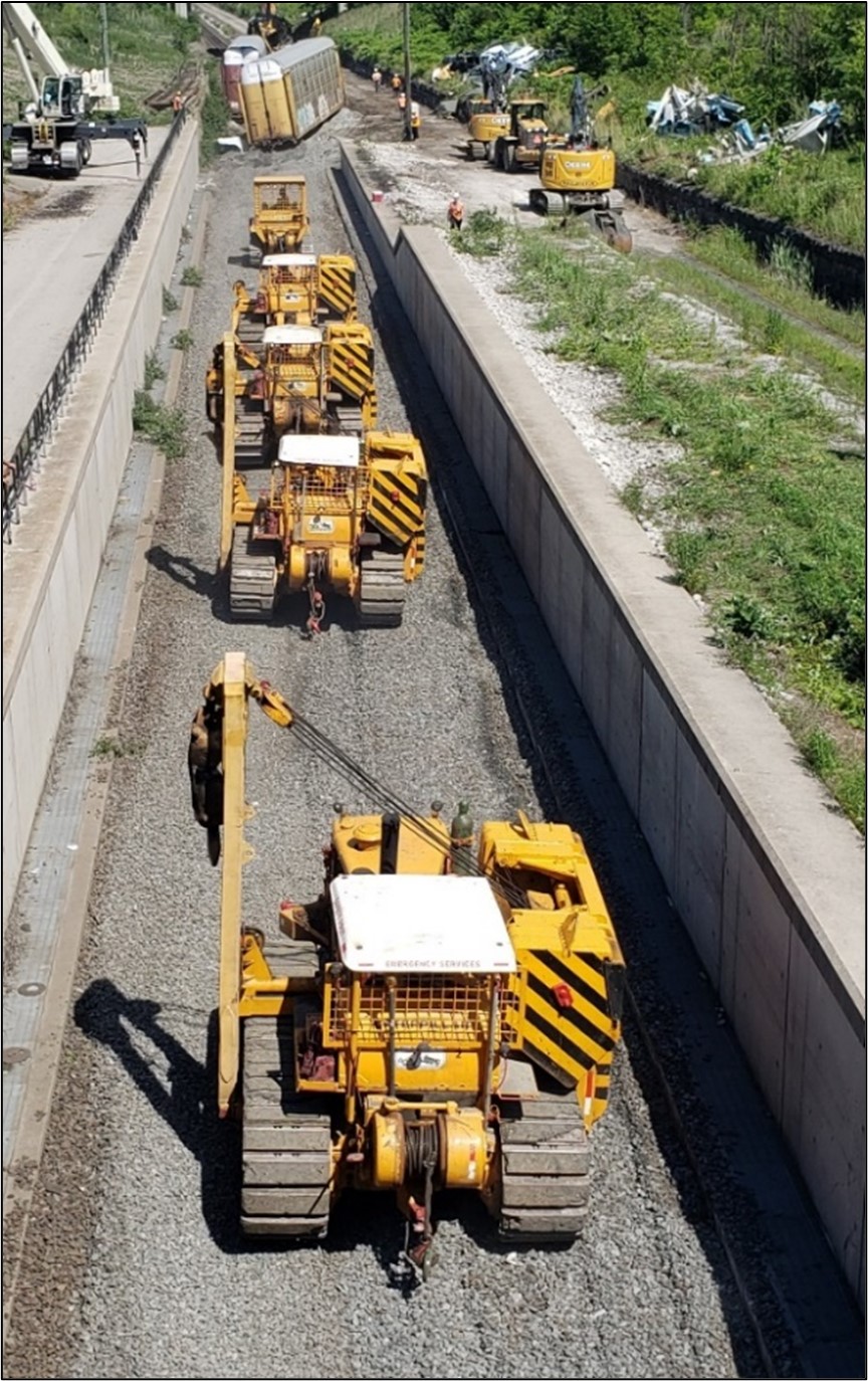
Clearing activities continued from the Canadian side of the tunnel. The work required cutting the rail in front of a derailed car and removing the rail from the tunnel. Then, each car was attached to heavy equipment (backhoes and bulldozers) using steel cables and dragged eastward out of the tunnel, where it was staged for examination on the Canadian side (Figure 18). All rolling stock that came to rest east of tank car UTLX 95205 (lines 69 to 98) were removed using this method.
Each car was examined after it was removed from the tunnel. Aside from DJJX 30478 (line 53), no other derailed rolling stock exhibited any pre-existing condemnable defects.
1.3.3 Accident investigation jurisdiction
Early in the morning of 04 July 2019, the border (Mile 60.63) was finally accessed (Figure 19), after freight car UCRY 15888 (line 61) was removed from the U.S. side of the tunnel.
The TSB, NTSB, and CN completed independent LER and DP log analyses. Although each used slightly different methodologies, inputs, and assumptions, the results were similar. The results confirmed that the train-initiated emergency brake application likely occurred as a result of a train separation between cars DJTX 30049 (line 52) and DJJX 30478 (line 53) between 400 feet and 600 feet east of the border, on the Canadian side. Subsequently, the TSB assumed jurisdiction for the accident investigation. The NTSB remained on site to exchange information and assist the TSB until the investigation site activities concluded.
On the morning of 05 July 2019, personnel from the TSB, NTSB, and CN walked the tunnel from east to west and jointly recorded the measurements for the car locations that had been marked on the reinforcement walls during site-mitigation activities (Appendix A). By 1430, all wreckage had been cleared from the tunnel, and track restoration work began.
On 06 July 2019, the TSB and NTSB investigation site activities concluded.
1.3.4 Track restoration
By 1200 on 09 July 2019, CN had restored all of the track within and outside of the tunnel.
A total of about 9000 feet of track was replaced following the accident of which approximately 7500 feet was damaged, destroyed, or removed as a result of the derailment. Of the 7500 feet of track:
- about 4500 feet of track within the tunnel was damaged or destroyed as a direct result of the derailment, and
- about 3000 feet required replacement because the track was removed before the derailed cars were pulled from the tunnel, or because the track was damaged while the derailed cars were being pulled from the tunnel.
An additional 1500 feet of track was changed out as an opportunistic replacement since CN had new rail, ties, clips, ballast, labour, and equipment on site for the tunnel track restoration.
During site-mitigation activities, the track affected by the derailment was examined, and no rail or track defects were observed.
Once restoration was complete, the first train passed through the tunnel at 1600 on 09 July 2019.
1.4 Subdivision information
The Strathroy Subdivision consists of a single main track that extends from Mile 0.0 (London, Ontario) to Mile 61.7 (Port Huron), where it joins Mile 334.2 of the CN Flint Subdivision. Train movements are governed by the centralized traffic control system method of train control, as authorized by the Canadian Rail Operating Rules and, at the time of the occurrence, were dispatched by an RTC located in Montréal, Quebec.
The Transport Canada (TC)-approved Rules Respecting Track Safety, also known as the Track Safety Rules (TSR), outline the classes of track and the associated maximum permitted train speeds for each class. Track within the tunnel is Class 4 track and has an authorized track speed of 60 mph for all trains. The TC-approved Rules Respecting Key Trains and Key Routes, otherwise known as the Key Train Rules (KTR), further restrict key trains to a maximum speed of 50 mph on main track.
1.5 Canadian National Railway Company Paul M. Tellier Tunnel information
The tunnel is 6130 feet long and commenced operation in 1994. It connects the Strathroy Subdivision in Canada with the Flint Subdivision in the U.S. and extends from the tunnel’s east portal in Sarnia (Mile 59.98) to the tunnel’s west portal in Port Huron (Mile 61.14).
At the time of the occurrence, rail traffic through the tunnel consisted of an average of 18 freight trains per day. The total rail traffic through the tunnel averages about 125 million gross tons per mile (MGTM) per year.
The tunnel was built with a 20 000 L capacity stainless-steel sump that was designed to remove excess moisture from the tunnel. The tunnel was also equipped with toxic gas detectors, alarms, and a ventilation system.
1.5.1 Track
The track into and through the tunnel is Class 4 single main track having a mostly tangent alignment with only 3 shallow curves. The track has an approximate 2.00% descending grade from the eastern crest (Mile 59.32) to near the international border (Mile 60.63), where it levels out slightly, followed by an ascending grade of up to 2.10% to just past the west end of the Strathroy Subdivision (Mile 61.70) in Port Huron (Figure 9).
The track consists of 136-pound continuous welded rail (CWR) manufactured by Nippon in 2009. The rail was installed in 2009 and secured to concrete ties with insulators and Pandrol’s e-clip fasteners. The ballast was 3-inch diameter crushed rock, the cribs were full, and the ballast shoulders extended to each side of the tunnel to facilitate walking within the tunnel.
The track through the tunnel was inspected and maintained in accordance with company and regulatory requirements, with no defects noted, and was in good condition.
1.5.2 Toxic gas monitoring and alarm system
To protect employees from a DG release in the tunnel, the tunnel is equipped with a toxic gas monitoring system and an alarm system. The system, which uses sensors to provide continuous monitoring for the concentration of various gases in the tunnel, was also designed to activate an alarm if the monitoring equipment malfunctions or is damaged as the result of a derailment and thus becomes inoperable.
The crew reported that the lights and ventilation fans at the west end of the tunnel were off following the derailment, although the RTC display screen showed that they were activated. However, the indications on the RTC screen only identify that the system is activated and do not provide feedback on the state of the system. The only way to determine if the lights, fans, or toxic gas monitoring systems were damaged during the derailment or if there was an actual toxic gas release, was to physically inspect the tunnel.
1.5.3 Tunnel ventilation system
The tunnel is equipped with ventilation fans that are automatically activated as required. Employees can ask an RTC to turn the fans on or off and can specify the direction of airflow.
1.5.4 Tunnel emergency procedures
The CN Strathroy Subdivision Timetable No. 43 (dated 15 September 2015) outlines emergency procedures for the tunnel. When a movement is stopped by an emergency application of air brakes, either entering, occupying, or exiting the tunnel, train crews must follow the tunnel’s emergency procedures. While the procedures outline a number of items that must be complied with, there are no specific instructions or guidance that require a train crew to wait for confirmation from the RTC that it is safe to enter the tunnel before conducting a train inspection, such as following a derailment.
1.6 Train operations within the tunnel
CN train operations through the tunnel incorporate the use of gravitational force and momentum, similar to a roller coaster. In general terms, trains typically approach the tunnel portal at around 15 mph and are allowed to accelerate unrestricted (without the use of locomotive throttle or train air brakes) down the grade, using gravitational force and momentum until the head end reaches the bottom of the grade. At this point, the locomotive(s) throttle is gradually increased to
- compensate for the inevitable loss of momentum and overcome the increasing train resistance due to the gravitational and rolling resistance forces on the ascending grade,
- begin to stretch and pull out the train slack as the head end starts to ascend the grade, and
- avoid a train stall condition in the tunnel.
Due to the track profile through the tunnel, CN has specific train operating criteria that LEs must adhere to when operating a train through the tunnel to minimize draft forces and the chances of a train separation when a train ascends out of the tunnel.
1.6.1 Canadian National Railway Company instructions for operating a train through the tunnel
The CN Strathroy Subdivision Timetable No. 43 (15 September 2015) outlined train-handling instructions for trains operating through the tunnel. At the time, it was expected that a lead locomotive would likely lose communication with a DP remote locomotive as a train negotiated the tunnel. The Timetable No. 43 train-handling instructions took this into consideration and outlined, in part, that:
All trains should approach the Tunnel crest (Hobson for Westward movements; 16th Street Port Huron for eastward movements) not exceeding 15 MPH.
On Distributed Power (DP) trains, before the DP Lead consist enters the tunnel:
DP trains are to be placed into Independent Control Mode by utilizing the MOVE TO BACK key on the DP Operations screen to put up the DP fence between the DP Lead (“A”) consist and DP Remote (“B”) consist.
Using the TRACTION keys on the DP Operations Screen, place the throttle of the DP Remote consist to Throttle 2 for a Remote consist containing a single locomotive or to Throttle 1 for Remote consist(s) containing 2 or more locomotives.
[…]
Distributed Power (DP) trains will lose DP Communications after the Lead consist enters the tunnel. Once DP Comm Loss is established, DP trains must remove the DP fence by pressing the MOVE TO FRONT key until the DP fence disappears from the DP Operations screen. The Remote consist(s) will retain their prior Throttle setting until DP Communication restores. Footnote 19
In June 2016, CN upgraded the radio signal repeater system in the tunnel. As a result of this upgrade, a loss of communication was no longer expected between a lead locomotive and a DP remote locomotive. Following the upgrade, on 24 October 2016, CN issued Operating Bulletin No. 508 for the Great Lakes Sub-Region, which modified the Port Huron/Sarnia Tunnel Train-Handling Instructions accordingly. These modified instructions, outlined in Operating Bulletin No. 508 and the subsequent Rule 83 (c) Summary Bulletin for the Strathroy Subdivision, state, in part, that:
All trains should approach the Tunnel crest (Hobson for Westward movements; 16th Street Port Huron for eastward movements) not exceeding 15 MPH.
Distributed Power trains should be operated in DP synchronous mode (without the DP fence up) starting down the descending grade towards the tunnel entrance.
The DP operations screen should be on the Control Menu level with the MOVE TO BACK key visible as it will be utilized later.
On DP Trains the MOVE TO BACK key should be pressed to put the DP fence up before the Lead locomotive enters the tunnel. At that time use the LESS TRACTION key to reduce DP remote throttle to Idle, if it is not already in Idle.
[…]
On DP trains, use the footage counter to judge when the DP Remote consist reaches the bottom of the tunnel. At that time begin to use the MORE TRACTION and LESS TRACTION keys to maintain DP Remote throttle 2 positions less than the Lead locomotive throttle position. (For example, if Lead locomotive throttle is in Position 5, have DP Remote throttle in Position 3 […], etc.)Footnote 20
CN makes timetable revisions by issuing a Rule 83 (c) Summary Bulletin quarterly. As a result, Operating Bulletin No. 508 was incorporated into the subsequent CN Eastern Canada Region – Great Lakes Sub-Region Rule 83 (c) Summary Bulletin for the Strathroy Subdivision. The modified Port Huron/Sarnia Tunnel Train-Handling Instructions were carried forward with each subsequent re-issue of the summary bulletin until they were included in the revised CN Strathroy Subdivision Timetable No. 44, issued on 01 September 2020.
1.7 Recorded information
Based on the LER data recovered from all 3 locomotives, the train departed from the CN Sarnia Yard, travelled westward, and arrived at the east crest of the tunnel at a speed of about 11 mph.
After reaching the crest, the train subsequently entered the tunnel and continued to accelerate on the descending grade due to the gravitational force until the head end of the train arrived at the bottom of the tunnel.
At the bottom of the tunnel, the LE applied throttle on the 3 locomotives. As the train ascended the west side of the tunnel, an undesired train-initiated emergency brake application (UDE) occurred, and the train came to a stop.
Some recorded events exhibited minor differences in time between the head-end locomotives and the DP remote locomotive; these differences ranged from 1 to 3 seconds. Such differences were primarily due to expected transmission delays of radio signal communication within the tunnel. In general, all 3 locomotives operated synchronously. The corresponding train-handling events are summarized in Table 1.
| Event | Time (EDT) | Duration (seconds) | Run time (seconds) | Mile | Distance (feet) | Speed (mph) | Throttle position | Brake cylinder air pressure (psi) | Brake pipe air pressure (psi) | End of train air pressure (psi) | Emergency brake |
|---|---|---|---|---|---|---|---|---|---|---|---|
| T-1 | 0402:18 | 12 | 0 | 57.89 | 305 659 | 0 | T-1 | 60 | 89 | 89 | No |
| Idle | 0402:30 | 32 | 12 | 57.89 | 305 659 | 1 | Idle | 1 | 89 | 89 | No |
| T-1 | 0403:02 | 58 | 44 | 57.89 | 305 659 | 0 | T-1 | 50 | 88 | 89 | No |
| T-2 | 0404:00 | 376 | 102 | 57.90 | 305 712 | 1 | T-2 | 0 | 88 | 89 | No |
| T-1 | 0410:16 | 213 | 478 | 58.60 | 309 408 | 10 | T-1 | 0 | 88 | 89 | No |
| Idle | 0413:49 | 299 | 691 | 59.22 | 312 682 | 11 | Idle | 0 | 88 | 89 | No |
| T-1 | 0418:48 | 7 | 990 | 60.65 | 320 232 | 37 | T-1 | 0 | 88 | 89 | No |
| T-2 | 0418:55 | 16 | 997 | 60.73 | 320 654 | 39 | T-2 | 0 | 88 | 89 | No |
| T-3 | 0419:11 | 25 | 1013 | 60.90 | 321 552 | 41 | T-3 | 0 | 88 | 89 | No |
| BPP drop | 0419:36 | 1 | 1038 | 61.19 | 323 083 | 44 | T-3 | 0 | 71 | 89 | No |
| UDE/ PCS | 0419:37 | 1 | 1039 | 61.20 | 323 136 | 44 | T-3 | 3 | 4 | 89 | Yes |
| Idle | 0419:38 | 2 | 1040 | 61.22 | 323 242 | 43 | Idle | 11 | 0 | 89 | Yes |
| EIE | 0419:40 | 3 | 1042 | 61.24 | 323 347 | 42 | Idle | 40 | 0 | 89 | Yes |
| EOT 0 psi | 0419:43 | 1 | 1045 | 61.27 | 323 506 | 41 | Idle | 73 | 0 | 8 | Yes |
| Bail | 0419:44 | 31 | 1046 | 61.29 | 323 611 | 40 | Idle | 60 | 0 | 0 | Yes |
| 0 mph | 0420:15 | n/a | 1077 | 61.46 | 324 509 | 0 | Idle | 14 | 0 | 0 | Yes |
Notes:
BPP: brake pipe pressure
EDT: Eastern Daylight Time
EIE: engineer-initiated emergency
EOT: end of train
PCS: pneumatic control switch
UDE: undesired train-initiated emergency brake application
* Bailing off refers to draining the compressed air from the locomotive brake cylinders after an automatic brake application. This is accomplished by depressing the independent brake valve, thereby preventing or nullifying an application of the automatic brakes on the locomotive.
The LE generally adhered to CN train-handling guidelines when approaching the tunnel and while descending to the bottom of the tunnel. However, after reaching the bottom of the tunnel, the LE did not follow the CN train-handling instructions that had been modified in October 2016 and were in force at the time of the accident. According to these instructions, the LE had to change the operating mode of the DP remote locomotive to independent motoring in order to maintain the remote consist throttle at idle or 2 positions less than the lead locomotive throttle position.
Instead, the LE operated all 3 locomotives in DP synchronous mode, with all locomotives in the same throttle position, which was consistent with the Strathroy Subdivision Timetable No. 43 requirements that were in place up until October 2016.
1.8 In-train forces
In-train forces are dynamic buff (compressive) and draft (tensile) forces applied to the rail cars and their components when a train is in motion. These longitudinal forces put stress on rail cars, their components, and potentially the track infrastructure.
A train travelling on tangent track generates steady-state longitudinal in-train forces. On an ascending grade, a train generates draft force. The magnitude of the draft force is determined by the train’s trailing tonnage, the amount of locomotive tractive effort, ascending grade slope, and train rolling resistance. Similarly, on a descending grade, when a train is decelerating or maintaining a constant speed, a train generates buff force. The magnitude of the buff force is determined by the amount of locomotive dynamic brake and air brake retardation, the train’s trailing tonnage, and the descending grade slope.
Train slack refers to the longitudinal movement at the ends of a car and the cumulative movement of cars within a train. The movement occurs as the in-train forces are transmitted between cars during operation. Train slack can cause speed differentials within a train in the form of a run-inFootnote 21 or run-outFootnote 22 of slack. As a train starts moving forward, one car at a time, the slack is pulled out. The amount of slack can vary depending on the type of draft system installed on each car.
Effectively managing in-train forces within established safe limits requires a systematic approach that considers
- train marshalling (including placement of DP locomotives within a train);
- train handling; and
- the topography of the territory a train is operating on and the associated track grade and curvature.
1.8.1 Coupler and draft system
A coupler is a mechanical apparatus installed on the end of each rail car to connect the cars together on a train. A coupler assembly usually includes a coupler arm, a knuckle, a knuckle pin, and a locking mechanism.
In conjunction with the coupler, a draft system is installed on both ends of a rail car to help absorb the energy associated with train movements. Draft systems protect rail cars and lading by absorbing energy during impacts and limit relative motion between coupled cars as coupling forces are transmitted through a train. Footnote 23 Draft systems are essentially shock absorbers designed to compress and extend by a certain amount when a force is applied to them. Because of draft systems, the connection point between coupled cars has some amount of slack, depending on the system’s design.
The draft system may use either standard friction gears or end-of-car cushioning devices (EOCCDs), depending on the design and intended use of the rail car.
- A standard friction draft gear is the most basic draft system and provides a limited amount of shock protection. The maximum displacement of the draft gear due to the extension and retraction, referred to as coupler stroke length, is limited to only about 3½ inches.
- An EOCCD is designed to provide additional protection against shock impacts. An EOCCD’s cushion unit has a long-shank coupler and a piston that provides a long travel stroke, ranging from 10 to 18 inches, owing to the cushion unit moving in and out of the EOCCD housing.
EOCCDs are designed to reduce shock impacts and lading damage during yard switching activities and they can also help to dampen in-train forces in some situations. However, when a large number of EOCCDs are grouped together and concentrated in one section of a train, they can have a compounding and adverse effect on slack action, resulting in higher in-train forces. Thus, when there are large cuts of cars equipped with EOCCDs on a train, and particularly loaded EOCCD cars, the LE must be vigilant in order to control the slack action. If care is not taken, a sudden run-out or run-in of the train’s slack can result in a train pull-apart, string-line, or jackknife derailment. The Association of American Railroads (AAR) Train Make-Up Manual Footnote 24 indicates that cars equipped with EOCCDs add to train slack and can greatly increase in-train forces. In general, large cuts of empty cars or lightly loaded cars, whether equipped with friction draft gears or EOCCDs, should not be placed ahead of large cuts of loaded cars for trains operating on main track.
1.9 Train marshalling
The terms “train marshalling” and “train make-up” refer to the planned placements of rail cars in a train. There are different approaches to marshalling; for example, rail cars can be placed according to different criteria, such as length, weight, their destination, or other factors.
Marshalling criteria can serve to manage train safety by limiting the maximum in-train forces in specific operating scenarios. The interpretation of in-train forces and an in-depth understanding of how they affect train safety and derailment prevention are the cornerstones of best practices in train marshalling. The longer and heavier the train, the more important the order of heavy and light cars becomes in managing in-train forces.
Operating practices of the individual railways for train marshalling, train handling, and the use of DP all play a role in reducing the in-train forces. However, there are no common, industry-wide practices, guidelines, or limits to guide the development of safe operating practices for longer trains. Footnote 25, Footnote 26
At the time of this occurrence, there were no specific TC-approved train marshalling guidelines, nor were there regulatory requirements for limiting maximum in-train forces through marshalling. Footnote 27 Railways in Canada develop their own marshalling rules and instructions to help manage in-train forces and prevent derailments.
1.9.1 Canadian National Railway Company train marshalling practices
In 2010, CN began implementing system-wide and subdivision-specific train marshalling rules across its core network primarily related to train weight distribution. These rules were based on industry best practices, data analysis, and a risk-based approach to more effectively manage in-train forces. Additionally, train-service specific rules were implemented for conventional and DP trains to restrict maximum train weight and length, including verification of DP remote locomotive placement in a train.
To manage marshalling integrity and compliance, these rules were programmed into CN’s service reliability strategy (SRS) computer system program. To ensure that trains are assembled in compliance with marshalling requirements at CN’s major rail yards, the system automatically generates a marshalling alarm should a train journal be created with a non-compliance issue. Additionally, to verify ongoing compliance en route, an exception report is automatically generated as part of CN’s marshalling oversight escalation process if any non-compliance issues are detected whenever a train is scanned by a wayside automatic equipment identification site.
The marshalling rules include the following, among others:
- CN’s train marshalling Rule 1, which requires that no more than 33% of the train weight be placed in the rear 25% of the train’s length. CN relies on this general train weight distribution rule to prevent a train from having excessive weight on the tail end, a condition generally referred to as a “tail-end heavy” train.
- CN’s marshalling placement for mid-train DP locomotives, which is based on available horsepower and tonnage distribution, whereby 2/3 of the locomotive’s available tractive effort is in draft and 1/3 of the locomotive’s available tractive effort is in buff while also respecting CN’s remote zone Footnote 28 marshalling restrictions. This generally creates a small zone immediately ahead of the DP remote locomotive where the cars are in compression (a buff state). This serves to help dampen slack adjustments and absorb slack run-outs that can arise due to normal train handling adjustments and terrain characteristics. In general, the placement of a single mid-train DP remote locomotive is at about two-thirds of the total train length for a train with uniform weight and length distribution. Long-haul freight trains often carry a variety of car types (with different designs, lengths and/or weights) and invariably operate over various terrain types. Thus, generalized criteria are typically used for determining the optimal placement for a mid-train DP locomotive within a train consist.
Since CN initially implemented the rules, its train marshalling initiatives have evolved, and some elements have been moved into other CN documents, such as its Train Marshalling Job Aid (issued in July 2018) and its General Operating Instructions (GOIs).
While Rule 1 serves to generally manage train weight distribution, CN train marshalling criteria do not specifically require empty and/or lighter loaded cars, such as autorack cars, to be placed at the tail end of a train for CN main-track operations.
1.9.2 Occurrence train marshalling
Departing Sarnia, the train was marshalled with a block of lighter, loaded, 90-foot-long autorack cars equipped with long travel hydraulic EOCCDs located from line 70 to line 97. The DP remote locomotive was located between line 81 and line 82, with 12 autorack cars ahead of it, and 17 autorack cars behind it. The remaining tail-end cars on the train (line 98 to line 140) were mainly heavily loaded cars.
The train had 31.1% of its tonnage in the rear 25% of the train (Figure 20), which made the train borderline tail-end heavy, according to CN marshalling rules. Also, the DP remote locomotive placement between line 81 and line 82 did not comply with CN’s DP remote locomotive placement criteria. For the train departing Sarnia, according to CN’s Train Marshalling Job Aid, the DP remote locomotive should have been placed between lines 114 and 115 of the train.

1.10 Dynamics simulations
Dynamics simulations are theoretical in nature and are often performed to support derailment investigations. Simulation inputs contain a mix of recorded information (from the LER) and track engineering surveys, in conjunction with some reasonable assumptions based on experience. One of the goals of any dynamics simulation is to identify the combination of the factors and forces that produce results that most closely match the physical evidence observed on an accident site. Alternative simulations are also usually conducted to provide some clarity for potential mitigating strategies. This was the approach taken in this case.
Site examination identified that DJJX 30478 (line 53) was likely the first car to derail as the A-end of the car sustained structural failure when subjected to in-train buff (compressive) force while travelling in the tunnel.
In order to determine the magnitude of the maximum longitudinal buff force acting on the leading A-end of DJJX 30478, the TSB laboratory conducted a series of train dynamics simulations. The Train Energy Dynamic Simulation (TEDS) software was used to assess the in-train forces associated with the operation of the occurrence train as well as alternative train configurations and train-handling options. The maximum in-train buff force immediately before the undesired train-initiated emergency brake application at the first derailed car (DJJX 30478) was calculated to be approximately 388 kips in the occurrence condition.
The simulations conducted included the considerations discussed below.
1.10.1 Occurrence train
The baseline TEDS simulation estimated the forces acting on the train as it traversed the track profile through the tunnel. The train-handling script was created from the LER train-handling commands in real time. The train-handling commands were synchronously applied to the head-end locomotive consist and the DP remote locomotive. The train makeup and tonnage profile were as listed on the train journal.
1.10.2 Placement of autorack cars at the tail end of the train
For this simulation, the autorack cars equipped with EOCCDs were remarshalled to the tail end of the train from their original location ahead of and behind the DP remote locomotive. Otherwise, the simulation used the same track profile and train-handling commands as the occurrence train.
1.10.3 Placement of the distributed power remote locomotive
Using the same track profile, and with train-handling commands and train makeup otherwise remaining consistent with the LER and train consist, the DP remote locomotive was moved from its actual position in the train to between lines 114 and 115, in accordance with CN requirements.
1.10.4 October 2016 modification of the Canadian National Railway Company Train-Handling Instructions for the tunnel
The LE was operating the 3 locomotives in a synchronized fashion through the tunnel. This differed slightly from the CN train-handling requirements that were modified in October 2016 and in force at the time of the accident. The modified train-handling instructions call for the DP remote locomotive throttle to be in idle or in a throttle position 2 levels lower than the head-end locomotives, as the head-end locomotives ascended the grade.
A train-handling script was developed that incorporated the modified CN train handling instructions. The train handling was the same as the LER until the DP remote locomotive reached the bottom of the tunnel. From that point on, the head-end locomotives kept the same LER recorded throttle positions and the DP remote locomotive throttle was placed in either idle or 2 throttle positions lower than the head-end locomotives, as needed.
The same script was then applied to all simulations to evaluate the potential effect that the alternative train handling may have had.
Table 2 contains a summary of all simulation results that predict the maximum in-train buff force on car DJJX 30478 (line 53).
| Train configuration | Maximum buff force recorded using actual train handling (kips) | Maximum buff force recorded using CN train handling modified in 2016 (kips) |
|---|---|---|
| Occurrence train | 388 | 420 |
| Autorack cars moved to tail end | 235 | 232 |
| DP remote placed between lines 114 and 115 | 414 | 426 |
1.11 Regulatory requirements for freight car inspection and safety
The TC-approved Railway Freight Car Inspection and Safety Rules (2014) (freight car safety rules) and the U.S. FRA CFR, Title 49, Volume 4, Part 215—Railroad Freight Car Safety Standards (2011) (Appendix B), referred to as the freight car safety standards, provide the minimum safety criteria for freight cars operated by federally regulated railway companies in each country. While both have provisions that permit freight cars with defects to be moved to a location for repair, freight cars that travel within Canada or the U.S. must comply with these minimum criteria. The rules and standards are periodically modified as safety requirements evolve.
Efficient, seamless railway operation between Canada and the U.S. has become essential to the economies of both countries. As such, the regulatory requirements for freight car safety under the Canadian freight car safety rules and U.S. freight car safety standards are virtually identical. This regulatory alignment also serves to facilitate the interchange and interoperability of rail equipment that operates between all federally regulated rail carriers in both countries, as well as across the Canada/U.S. border.
1.11.1 Railway freight car interchange
Rolling stock is routinely transferred at a line point from one railway to another, a process referred to as interchange. Interchange occurs when a railway accepts a freight car for service on its line from another railway at line points and when crossing the Canada/U.S. border.
Formalized rules applicable to domestic and cross-border interchange between railway companies govern the safe operation, maintenance, and upkeep of rolling stock. Up until 2012, interchange between railways in Canada required that certified car inspectors from the handling railway physically inspect freight cars in accordance with the Association of American Railways (AAR) Field Manual of the AAR Interchange Rules (AAR Interchange Rules) prior to interchange. Similarly, the receiving railway was required to have its certified car inspectors inspect the freight cars against the AAR Interchange Rules before accepting the freight cars for service. During these interchange inspections, any freight cars identified with AAR condemnable defects were prohibited from interchange.
In 2012, the Canadian freight car safety rules were modified to more closely align with the U.S. freight car safety standards. The modification eliminated the need for a train to be inspected in accordance with the AAR Interchange Rules, provided there were records confirming that a safety inspection was performed by qualified personnel in accordance with either the Canadian Railway Freight Car Inspection and Safety Rules or the U.S. freight car safety standards. Consequently, AAR Interchange inspections were no longer required at an interchange point and/or when crossing the international border between Canada and the U.S.
1.11.2 Transport Canada-approved Railway Freight Car Inspection and Safety Rules
1.11.2.1 Safety inspections
Part 1, sections 4 and 5 of the TC-approved Railway Freight Car Inspection and Safety Rules (2014)outline the requirements for safety inspections of freight cars and states in part:
4.1 Subject to sections 20 and 21, of these Rules, a railway company shall ensure the freight cars it places or continues in service are free from all safety defects described in Part II of these Rules [...].
4.2 Safety inspections shall be performed by certified car inspector(s) at safety inspection locations
- where trains are made up;
- on cars added to trains;
- where cars are interchanged.
Such inspections may occur before or after a car is placed in a train at that location.
4.3 All freight cars that have previously received an inspection under subsection 5.1 of these Rules shall receive a safety inspection by a certified car inspector at the safety inspection location designated for that train by the railway company in the direction of travel.
4.4 A safety inspection is not required on blocks of cars that have previously received a safety inspection, in the direction of travel, for which the inspection status information is available.
4.5 A safety inspection is not required at an interchange point and/or when entering Canada provided there are records that indicate that a Safety Inspection, as per these Rules or an inspection by qualified mechanical personnel in the United States, was performed.
4.6 A freight car identified with a safety defect at other than a safety inspection location may be moved to another location for repair, in accordance with company procedures, including placing a loaded car for unloading when authorized by a person in charge, who shall ensure that:
- the car is safe to move;
- a means to protect the car’s safe movement is implemented, including identifying for the employees involved the nature of the defect(s) and the movement restrictions, if any;
- an empty car shall not be loaded until repaired; and
- the appropriate records will be retained for a period of ninety (90) days.
[…]
PRE-DEPARTURE INSPECTION
5.1 At locations where a certified car inspector is not on duty for purposes of inspecting freight cars, a pre-departure inspection of the train or the cars added shall be performed by a qualified person [...].Footnote 29
1.11.2.2 Safety defects
Part II of the Rules includes a list of safety defects that, when present, prohibit a railway company from placing or continuing a freight car in service. Section 14 of this part outlines safety defects for freight car bodies, which include structural components. Other than those for tank cars and box cars, the Rules state, in part:
14.1 A railway company shall not place or continue a car in service if:
[…]
(b) the car centre sill or stub sill is:
- broken;
- cracked more than 6 inches (152.40 mm); or
- permanently bent or buckled more than 2 ½ inches (63.50 mm) in any 6 foot (1.83 m) length;
(c) the car has a stub sill attachment with a crack greater than 6 inches;
[…]
(e) the car has a side sill cracked more than 6 inches (152.40 mm) when the car is not equipped with a full centre sill;
(f) the car has a broken cross bearer or body bolster;
(g) the car has a coupler carrier that is:
- broken;
- missing; or
- non-resilient, and the coupler has a type F head;
[…]
(i) it has a centre plate that:
- is improperly secured, with more than 25% of the fasteners missing and/or the centre plate observed to have moved;
- is broken; or
- has two or more cracks through its cross section thickness at the edge of the plate extending into the portion of the plate that is obstructed from view while the truck is in place;
[…]
(l) it is a loaded car with lading restraining devices worn or damaged to the extent that those devices will not restrain the load;
(m) an object extends from the side of a car body except by design;
(n) a car is not loaded in accordance with the prevailing “AAR General Rules Governing the Loading of Commodities on Open Top Cars”, or a circular of the Railway Association of Canada; or
(o) the car has any object which is not secured and could fall off. Footnote 30
1.12 Association of American Railroads manuals
The AAR publishes the AAR Interchange Rules that govern matters pertaining to the interchange of freight cars between railways and define responsibility for the cost of freight car repairs due to regular wear and tear and/or the implementation of safety improvements in accordance with AAR standards. Railways and car owners agree to follow the AAR Interchange Rules, and other applicable AAR manuals and publications, if they own or operate equipment that may be interchanged.
The AAR Interchange Rules contain additional, often more stringent, criteria than the TC-approved freight car safety rules and FRA safety standards that govern the safe operation and the maintenance of rolling stock. They detail the applicable condemning limits for all car parts and conditions. Once these limits are either reached or exceeded, repairs are warranted.
1.12.1 Field Manual of the AAR Interchange Rules
At the time of the accident, the 2019 AAR Interchange Rules governed the interchange of freight cars between railways. The AAR Interchange Rules relevant to this occurrence were reviewed and the following observations were made:
Rule 57 – Center Sills
The rule contains guidance for splice repairs on centre sills but has no information on stub sills Footnote 31 or stub sill defects that require attention.
Rule 58 – Side Sills
Rule 58 applies to side sills and Section A of the rule lists the cause for renewal to be “As required.” The rule does not provide any guidance on side sill defects that require attention.
Rule 89 – Conditions Governing Delivery and Acceptance
Rule 89 outlines conditions governing the delivery and acceptance of cars in interchange between railways. Section D specifies the conditions for a car not being acceptable in interchange.
Section D – Not Acceptable in Interchange
[…]
c. Car with underframe construction consisting of stub centre sills extending through the body bolster and branching into two or more side sills, offered by the owner, with side sill broken and or bent in excess of 1 ½ inches, between the body bolsters, unless covered by a defect card. Footnote 32
1.13 Universal Machine Language Equipment Register
The Universal Machine Language Equipment Register (UMLER) is the rail industry’s central repository for registered rail and intermodal equipment in North America. The UMLER system is managed by Railinc. One of the primary benefits of UMLER is that it contains a detailed list of specifications for each car. It also contains inspection dates required by AAR Interchange Rules for various rail car components, specific details on the internal and external dimensions, carrying capacities expressed in both U.S. gallons and cubic feet, as well as equipment light weight and loaded weight limits. It also lists special equipment on all rail cars, highway trailers, and containers that are used in railway interchange equipment or commercial service. There are over 2 million pieces of equipment registered in UMLER.
Following the Sarnia Tunnel derailment and examination of the 5 similar bathtub gondola cars at Port Huron, CN searched the UMLER database and identified about 2130 cars of similar type and vintage that were being used in scrap steel service in North America. By 16 September 2019, CN had inspected 416 of the 2130 cars identified as they came onto CN lines, and found that 36% (149/416) had defects according to the AAR Interchange Rules.
However, there were also challenges with searching UMLER to accurately identify the number of these car types that were built by this manufacturer and remained in service. Specifically:
- The data field for the equipment manufacturer is not consistently populated for cars built before 2010.
- The freight car built date field is populated by the car owner, but it is listed as confidential and so is not available to all users.
- The type of freight car body centre sill (stub or full) is not a designated field and so this information is not populated.
- When freight cars change ownership and/or are renumbered, the prior equipment identification field displays the prior car number, but the prior car detail information is not always available.
1.14 Types of gondola cars
There are 2 types of open-top gondola freight cars: flat-bottomed gondola cars and bathtub gondola cars.
1.14.1 Flat-bottomed gondola cars
In the early 1970s, prior to the development of bathtub gondola cars, the rail industry used flat-bottomed gondola cars (Figure 21) to transport resource commodities (e.g. coal). These cars are loaded and unloaded from the open top by mechanical means such as backhoes.
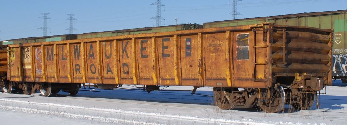
Flat-bottomed gondolas have a continuous centre sill that extends the length of the car. Heavy steel transverse cross-bearers and steel stringers secure the centre sill to the side sills to complete the underframe. Either a steel floor or a 2-inch-thick wood floor is secured to the underframe. The underframe and floor provide a robust platform for bulk lading but also add a substantial amount of weight to the car, which limits the amount of lading that could be carried.
Flat-bottomed gondolas are built with 70-ton or 100-ton capacities. The cars are of various lengths and range from 8 to 10 feet high from the rail. The 100-ton cars generally have a light weight of about 63 000 pounds and a load limit, or a lading capacity, of 200 000 pounds, for a total freight car loaded weight of 263 000 pounds gross rail load (GRL), which is standard for 100-ton freight cars.
1.14.2 Bathtub gondola car
In 1973, a lighter bathtub gondola car design was introduced to the railcar industry by Anthony Teoli of CP.Footnote 33 The lighter-weight cars were designed and built specifically for coal service. Each car was equipped with a fixed F70CC coupler on the B-end of a car and a rotary coupler on the A-end of the car. This arrangement facilitated rotary dump operation of the coal cars, so that at least 2 cars at a time could be unloaded at coal facilities, and eliminated the need for mechanical unloading.
The Teoli bathtub gondola (Figure 22) design was first built for CP by National Steel Car and Hawker Sidley in Canada. The original design ranged in length from 56 feet 10 inches to 58 feet 7 inches and was approximately 12 feet high (measured from the rail). The design was later sold to U.S. car builders, such as Berwick Forge & Fabricating Corporation (Berwick Forge), ACF and Thrall, which built a shorter 53-foot 1-inch-long version of the car to comply with U.S. coal rotary dump stations. By 1980, over 3200 such cars had been sold in the U.S. Presently, it is not uncommon to find cars of this type and vintage that have transitioned into maintenance-of-way or scrap iron and steel service as there are no industry restrictions on how these cars are utilized.
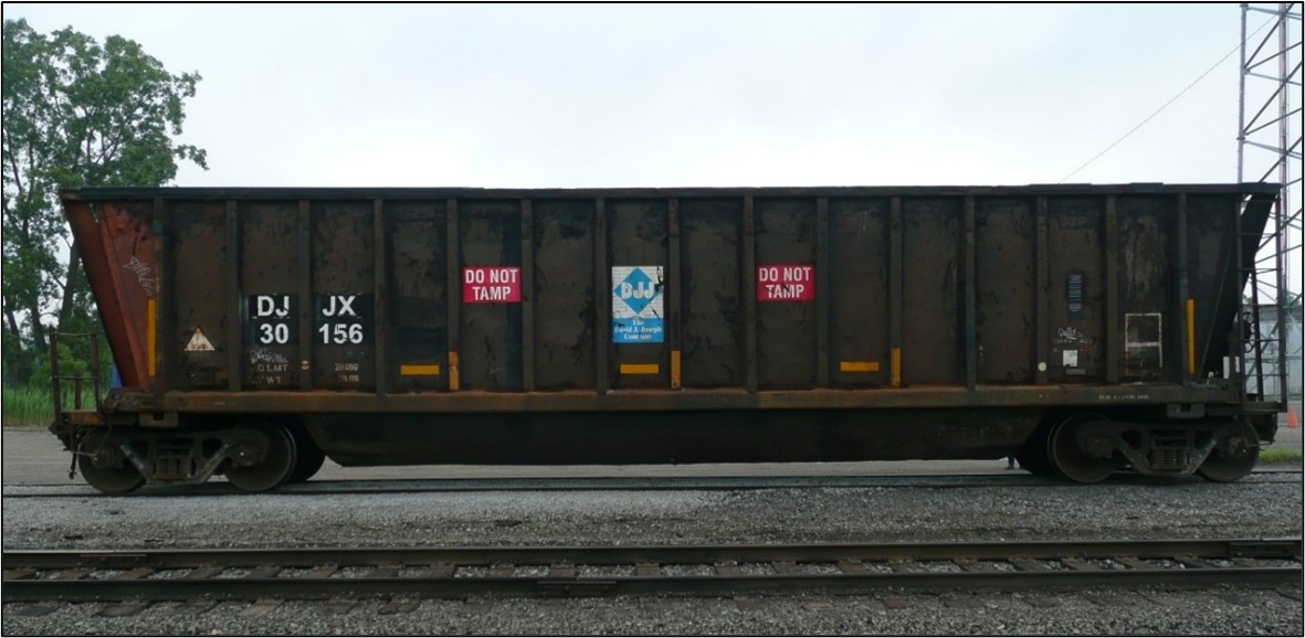
1.15 Bathtub gondola car construction
The bathtub gondola car (Figure 23) has downwardly converging side panels made of reinforced sheet steel. The sheets are welded solid to the top frame and the side sills of the car. Along each side of the car, side posts and slightly smaller intermediate side posts extend between the top frame and the side sills. All structural members are located on the outside of the end sheets, side sheets, and tub of the car shell. The side and end sheets are tapered, and all square corners are rounded.
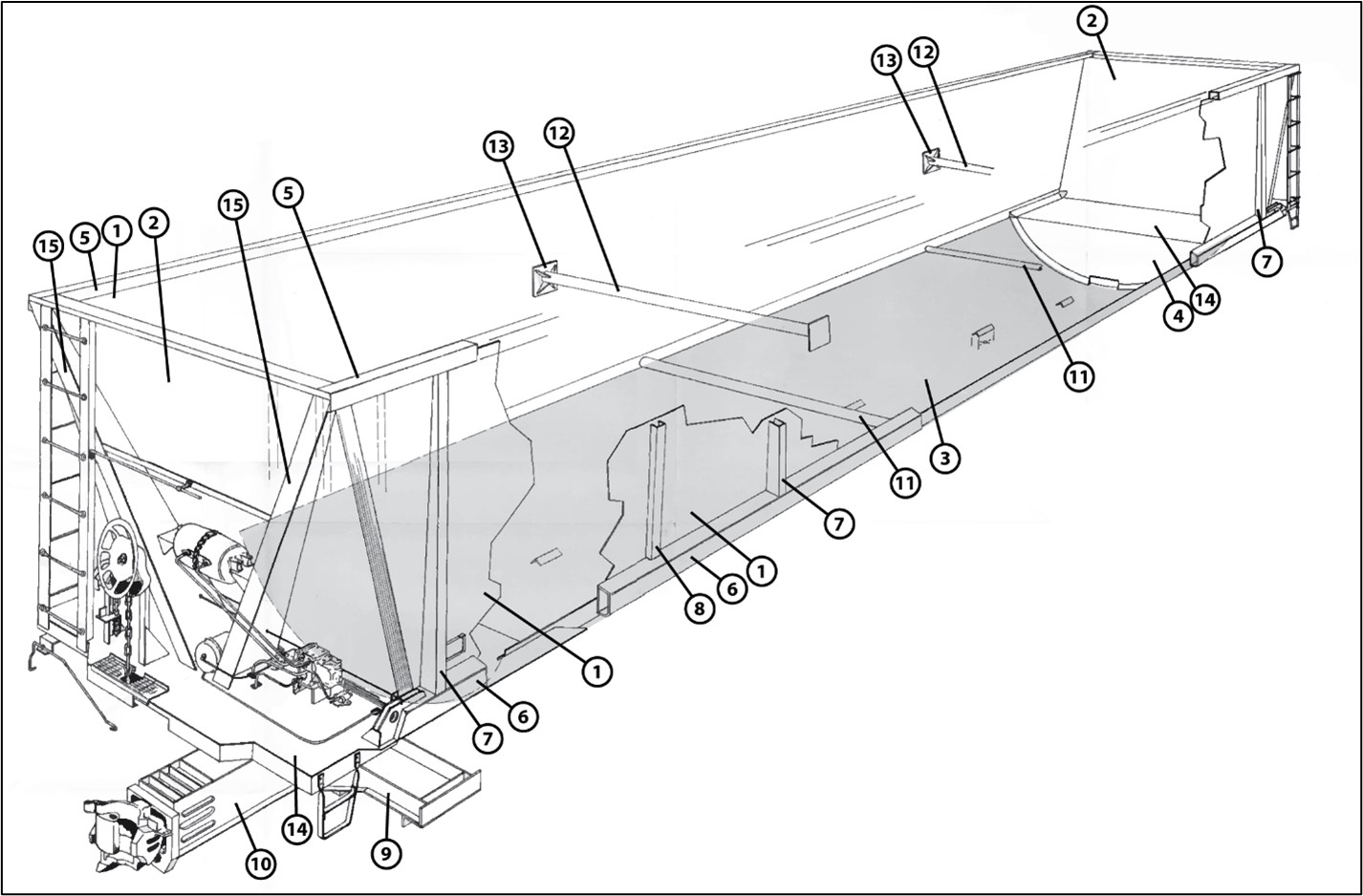
| Legend | ||
|---|---|---|
| 1 – Downward converging steel side sheet | 2 – Downward converging steel end sheet | 3 – Parabolic curved bottom sheet (tub) |
| 4 – Sloped end closure sheet for tub | 5 – Top frame | 6 – Side sill |
| 7 – Side post | 8 – Intermediate side post | 9 – Car body bolster |
| 10 – Stub centre sill (ahead and behind car body bolsters) | 11 – Bottom reinforcement crossbar | 12 – Top reinforcement crossbar |
| 13 – Mounting bracket for top reinforcement crossbar | 14 – Shear plate | 15 – V-shaped diagonal end braces |
To prevent lateral movement of the side panels, 2 bottom reinforcement crossbars are welded, at spaced intervals, to the side sills. Similarly, 2 top reinforcement crossbars, which are aligned vertically with the bottom reinforcement bars, are welded to a mounting bracket secured near the top frame.
Between the freight car trucks, a parabolic curved bottom steel sheet (tub) is integrated into the car structure and welded to the side sills. The ends of the tub are closed by welding sloping sheets that terminate at, and are welded to, the shear plates. The tub design eliminated the need for a conventional underframe with a full centre sill and transverse cross-bearers. When the car is loaded with coal, the pressure of the granular lading stabilizes the tub and evenly distributes the lading weight to the car’s underframe. The tub does not require reinforcing because it is primarily subjected to tensile stresses while in service. The lack of a full steel underframe results in a lighter-weight car, with a load capacity that is 10 000 pounds greater than conventional 263 000-pound GRL flat-bottomed gondola cars.
At each end of the car, the side sills are seated on shear plates that are attached to the car body bolsters, which are integral to the stub sills. With this arrangement, any longitudinal in-train forces exerted on a bathtub gondola car stub sill are transmitted through the shear plate and side sills along the length of the car to the other end, essentially bypassing the tub. The shear plates and side sills are exposed to higher loads and play an important part in carrying the longitudinal in-train forces while the cars are in transit.
The bathtub gondola car structural features produced a car that could carry more lading and provided a relatively obstruction-free car interior which, when combined with the rotary dump feature, permitted the free-flow of granular lading and rapid evacuation of the load with little or no residue left in the car.
1.15.1 Transporting bulk commodities
The lighter-weight bathtub gondola car was specifically designed for the uniform loading of bulk granular commodities. It was not intended for transporting other commodities and general merchandise. Once these cars are introduced into other types of service (e.g. transporting scrap steel and railway ties), the loading is no longer uniform and the structural members can be exposed to uneven loading that they were not designed for.
Compared to transporting granular lading, cars that transport scrap steel are subjected to a much more demanding service. Scrap steel may be loaded using a crane that controls a large magnet. Using the magnet, the crane picks up scrap steel material, sometimes as loose pieces of steel and sometimes as larger, compressed blocks of steel, and drops them into the car. As the car fills up, despite the “Do Not Tamp” signs on it, crane operators sometimes “tamp” the scrap steel to even out and compress the load so more material can be loaded. Loading may also be done by using a front-end loader and dropping scrap materials into the open top of the car.
A similar process is used for unloading steel from the car. Unloading operations may be done using a magnet or a backhoe that can reach deep inside the car to retrieve the scrap parts. When these cars are used in scrap steel service, repeated loading and unloading can sometimes result in damage to any interior structural elements that may be present. Such repeated extreme loading and unloading conditions can cause extensive damage to the car interior, including any reinforcement structure (such as the reinforcement brackets added to the occurrence car in 2012).
1.16 Car DJJX 30478
The UMLER records for bathtub gondola car DJJX 30478 were reviewed and revealed the following. The car was made of steel and manufactured in 1978 by Berwick Forge, which is no longer in business. The UMLER record identified that the car was 53 feet 1 inch long and 12 feet 5 inches high (measured from the rail). It had a light weight of 52 900 pounds and a load limit of 210 100 pounds, for a total loaded weight of 263 000 pounds GRL. The UMLER record also identified that the AAR had qualified the car for “Extended Service,” which applies to freight cars built new since 01 July 1974. Being qualified for extended service permits the car to operate for up to 50 years from the original manufacturing date without the need to re-qualify the car, unless otherwise noted; for example, tank cars must be re-qualified every 10 years.
The car had initially been used in utility coal service until about 2012, when it was purchased by the David J. Joseph Company Rail Equipment Group (DJJ Co.).
As originally designed, the bathtub gondola cars were equipped with reinforcement crossbars (2 upper and 2 lower) that were secured to side sills and top chords of the car interior to provide lateral stability. However, the crossbars were obstructions for loading scrap steel, and therefore, in preparation for the transition to scrap steel service, DJJ Co. proposed to modify the internal structure of these cars.
The proposed modification required that the 2 upper reinforcements be removed and replaced with vertical stiffeners while the 2 lower reinforcements were to be enclosed and protected. The modification had the appearance of 2 large steel u-channels (U-channels) inside the car to compensate for the structural change (Figure 24). The modification was also needed to reinforce the parabolic curved bottom sheet (tub) and secure it to the side sills and side sheets of the car.

Between 2008 and 2012, DJJ Co. submitted 4 requests with the proposed design change for its bathtub gondola cars to the AAR. The AAR stated that its review and approval of the proposed modification
was based on the requirements for the design of freight cars as found in AAR Standard M-1001, (Specifications for the Design, Fabrication and Construction of Freight Cars) which covers what is considered normal usage. The effectiveness of the modifications, like any reinforcement, will only provide satisfactory service if it is not exposed to an environment that stress the components beyond their inherent strength.
Subsequently, the AAR approved the modification for a total of 1650 DJJ Co. bathtub gondolas (Table 3) in preparation for transitioning to scrap steel service.
| AAR approval date | Number of bathtub gondola cars |
|---|---|
| 21 April 2008 | 168 |
| 01 September 2010 | 624 |
| 19 March 2012 | 247 |
| 07 August 2012 | 611 |
| Total | 1650 |
As of 14 August 2019, DJJ Co. had a total of 1331 such bathtub gondolas remaining in scrap steel service, 692 of which were built by Berwick Forge.
1.16.1 Car movement activity
Records of DJJX 30478 car movement activities were reviewed for the 6 months prior to the accident. The review identified that DJJX 30478 travelled frequently within and between Canada and the U.S. During this time period, the car
- was interchanged 16 times between railways, and
- traversed the international border between Canada and the U.S. at least 8 times.
- On 3 occasions, DJJX 30478 travelled empty from a CN line point in the U.S to MacMillan Yard in Canada.
- On 5 occasions, DJJX 30478 was loaded with scrap steel and travelled from MacMillan Yard to a CN line point in the U.S.
1.16.2 Inspection and maintenance records
Between 08 March 2019 and 28 June 2019, DJJX 30478 received 24 CCIs conducted at various CN line points with no significant defects noted.
No substantial defects were identified at pull-by inspections or wayside inspection systems, nor were any identified during interchange inspections.
DJJX 30478 car maintenance records for the year prior to the accident were reviewed and revealed that the car required only routine maintenance during this time (Appendix C).
1.17 Follow-up examination of car DJJX 30478 (line 53) and 5 other DJJX bathtub gondola cars
In late July 2019, the TSB and NTSB attended CN’s Port Huron Yard and conducted a more detailed examination of the failed bathtub gondola car, DJJX 30478 (line 53), and 5 other DJJX bathtub gondola cars of similar vintage that were selected from the head end of the occurrence train for subsequent examination. Details of the 6 cars are contained in Appendix D.
1.17.1 Detailed examination of car DJJX 30478 (A-end)
The DJJX 30478 remaining car body was placed upright along the track to commence the detailed examination (Figure 25). The A-end had been severed from the car.
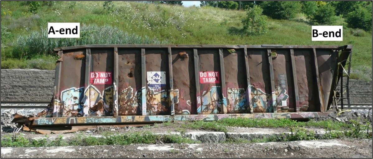
From the A-end, looking inside the car, extensive deterioration was observed throughout (Figure 26). The steel reinforcements that had replaced the crossbars were extensively corroded, and the bottom portions that reinforced the tub were missing. The welds that had secured the reinforcements to the tub were severely corroded, indicating that this condition had likely existed for some time prior to the accident.

The car had a number of pre-existing defects, was heavily corroded, and exhibited numerous cracks in the welds that secured the A-end shear plate to the stub sill, car body bolster, and side sills. The left-side sill, part of the body bolster, and a portion of the shear plate were torn off (Figure 27).

Legend:
1 – stub sill
2 – body bolster
3 – shear plate
4 – side sill
5 – coupler
L – left
R- right
FWD – forward.
*Yellow arrows in (a), (b) and (c) indicate line of primary fracture
*White arrows in (b) identify smearing and gouging from contact with components as separation occurred.
*White arrow in (e) identifies preferential corrosion
*Green arrow in (d) identifies location of fillet enclosure corrosion
In addition, the following observations were made:
- The shear plate fracture progressed up to 24 inches longitudinally along the left side of the stub sill (Figure 27 (a) and (b)) before it transitioned diagonally and extended outboard along the car body bolster.
- The shear plate fracture surface was heavily corroded, with no plastic deformation observed, a feature that is consistent with a fracture that occurred due to a structural defect rather than an overload.
- The shear plate that remained on the left side, and aft of the body bolster, was severely buckled and displayed multiple secondary fractures.
- The left side of the car body bolster had fractured about 30 inches outboard of the stub sill (Figure 27 (c)). The bolster fracture surface lacked any visible plastic deformation, which indicated that it also likely occurred due to a structural defect.
- The fracture surface of the car body bolster vertical wall was layered and heavily corroded (Figure 27 (e)), which suggests that severe preferential corrosion likely occurred in the steel plate at this location.
1.17.2 Detailed examination of car DJJX 30478 (B-end)
DJJX 30478 was moved onto its side in order to examine the B-end underframe structure. The B-end did not separate from the car body or sustain any impact damage during the derailment. Similar to the A-end, pre-existing cracks were observed in the welds that secured the B-end shear plate to the stub sill, car body bolster, and side sills (Figure 28).
Cracks in the areas illustrated in Figure 28 can result in increased stress and can negatively affect the ability to transfer in-train forces through the shear plates and side sills, as per the original car design. In some cases, this can result in structural failure.

Legend:
1 – stub sill
2 – car body bolster
3 – shear plate
4 – side sill
*Yellow arrows indicate cracks.
1.17.3 Follow-up examination of 5 other DJJX bathtub gondola cars
The 5 DJJX bathtub gondolas of the similar vintage that were removed from head end of the occurrence train following the accident included DJJX 30156 (Figure 22), which was a car of the same design as failed car DJJX 30478 (line 53). Both cars were manufactured in 1978 by Berwick Forge.
The 4 other DJJX bathtub gondola cars were “Coalveyors” manufactured in 1980 by ACF. The following observations were made during the follow-up examination:
- Two of the ACF cars were in serviceable condition, as they had been extensively repaired and the side sills were reinforced.
- Similar to the failed car (DJJX 30478), DJJX 950782 (line 1), DJJX 30156 (line 13), and DJJX 950965 (line 50) each exhibited similar cracking in the welds that secured the shear plates to the stub sill, car body bolster, and side sills at each end of the car. The cars also exhibited bulges, buckles, cracks, and/or sagging in key structural components such as stub sills, shear plates, and side sills.
Following the examination, DJJX 950782, DJJX 30156, and DJJX 950965 were selected for compressive end load testing and sent to the National Research Council Canada (NRC) in Ottawa, Ontario.
Wreckage from DJJX 30478 was sent to the TSB Engineering Laboratory in Ottawa for failure analysis.
1.18 Other similar bathtub gondola failures
The failure of DJJX 30478 was not an isolated occurrence. In May 2018, a U.S.-based railway had issued an internal early warning letter related to bathtub gondola cars of similar type and vintage after some of the cars experienced a catastrophic failure of the car body resulting from cracks in the side sills. The precise number of failures was not recorded in the letter.
1.19 National Research Council Canada compressive end load testing
The AAR Manual of Standards and Recommended Practices, Specification M-1001 (AAR MSRP) sets forth the minimum requirements for the design and construction of new freight cars for use in Canada and the U.S. Freight cars constructed in accordance with the AAR MSRP after 01 July 1974 are qualified for 50 years of service without any need for re-qualification, provided they met the original AAR design criteria, which includes compressive end load testing. Footnote 34
Since the cars were qualified for 50 years of service, the TSB contracted NRC to perform compressive end load testing of the 3 bathtub gondola cars selected from CN’s Port Huron Yard to evaluate the service worthiness of the bathtub gondola car type that incurred structural failure in the Sarnia Tunnel. The testing assessed the ability of these 3 bathtub gondola cars to withstand the required longitudinal compressive static load in their current worn state after 40 years of service. The testing was scheduled as follows:
- On 17 December 2019, testing commenced with the car that exhibited the least damage, DJJX 950965 (line 50).
- On 31 January 2020, testing continued with the car that displayed moderate damage, DJJX 950782 (line 1).
- On 02 March 2020, testing concluded with the car that exhibited the most damage, DJJX 30156 (line 13), which was a car of the same design as DJJX 30478 that failed in the tunnel.
1.19.1 Car inspections
NRC completed visual inspections of each car prior to testing. In each case, extensive damage was identified. Each car showed signs of the following, among other problems:
- Buckled side posts
- Ruptured side sheets, end sheets, and tub sections
- Negative side sill camber
- Buckled top chord (horizontal)
- Various cracks and corrosion
To supplement the visual inspections, pre- and post-test measurements were taken for top chord (frame) straightness and side sill camber (sag) to identify any structural flaws. A negative change in top chord straightness indicates an inward deformation. A negative value in side sill camber indicates a downward deformation. The results for both the left and right sides of each car are contained in Table 4 below:
| Test | Pre-test top straightness (inches) | Post-test top straightness (inches) | Pre-test side sill camber (inches) – AAR limit 1½ inches | Post-test side sill camber (inches) – AAR limit 1½ inches | ||||
|---|---|---|---|---|---|---|---|---|
| Left | Right | Left | Right | Left | Right | Left | Right | |
| DJJX 950965 (least damage) | −7 | −73/16 | −7¼ | −71/16 | -19/16 | −13/16 | −1½ | −13/16 |
| DJJX 950782 (moderate damage) | −8 | −5 | −79/16 | −51/8 | −2¼ | −21/16 | −25/16 | −115/16 |
| DJJX 30156 (most damage) | −3 | −3¾ | −3 | −41/8 | −15/16 | −2¾ | −13/16 | −33/8 |
1.19.2 Test procedure
Full-scale testing was performed using NRC’s squeeze and tension frame to assess the structural integrity of each empty car. The frame itself is composed of 2 fabricated I-beams with a fixed crosshead and a translating reaction frame crosshead located by a series of shear plates to allow for variable-length cars under test. Both crossheads are constrained under test, and a longitudinal load is applied to the car through a hydraulic ram (Figure 29).

A series of displacement transducers and strain gauges were used to record test results. Prior to the test, the instrumentation was placed at designated locations on each car. The instrumentation recorded forces and measured any displacement that occurred during testing. A 32-channel data acquisition system recorded the instrumentation signals for the tests. A 600-ton capacity hydraulic cylinder was used to apply the required loads to the ram during the tests.
1.19.3 Results of compressive end load testing
The test requires that a horizontal compressive static load of 1000 kips (1 000 000 pounds of force) be applied at the centreline of the draft system and held for a minimum of 60 seconds before releasing the pressure. This procedure must be completed 3 consecutive times without any structural failure in order for a car to pass the test.
The following results were recorded:
- The 2 cars built by ACF (DJJX 950965 and DJJX 950782; lines 1 and 50) each survived 3 consecutive applications of 1000 kips.
- The Berwick Forge–built DJJX 30156 (line 13) experienced structural failure at about 628 kips (628 000 pounds of force) during the first force application. As a result, the test could not be repeated.
- The force displacement graph for the test exhibited a change in slope at about 450 kips (450 000 pounds of force), which indicates that DJJX 30156 was behaving non-elastically prior to failure.
The 2 bathtub gondola cars manufactured by Berwick Forge—DJJX 30478, which failed in the tunnel, and DJJX 30156, which failed the compressive end load testing—each sustained structural failure in a similar area of the A-end left side (AL) side of each car (figures 30 and 31).
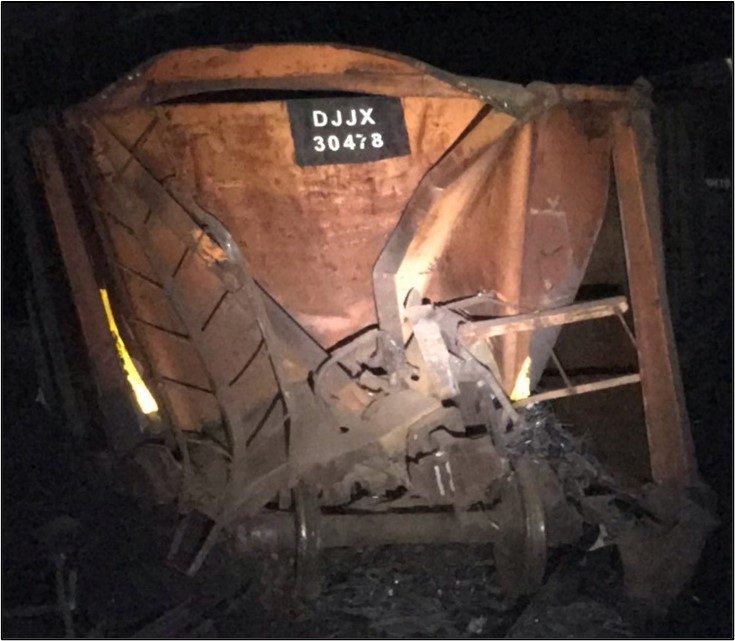
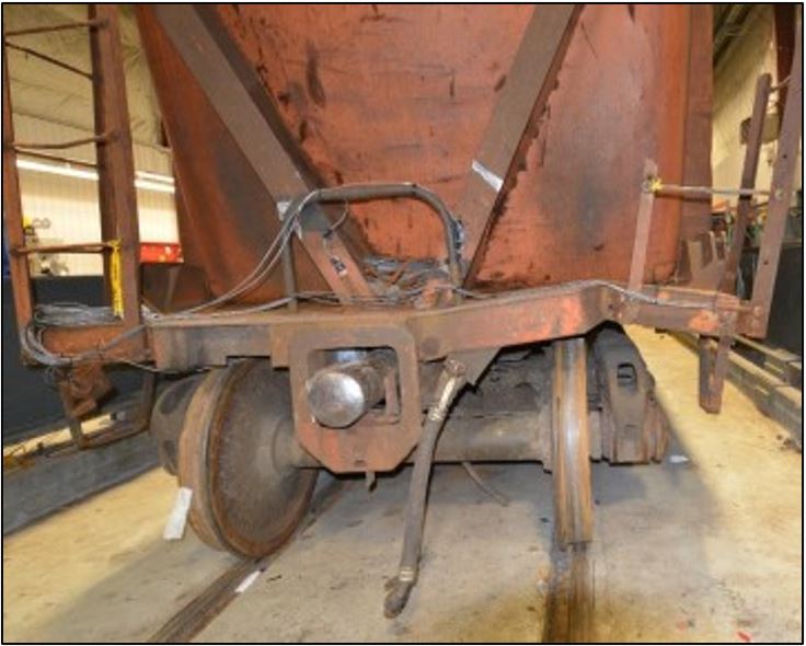
1.19.4 Shear plate thickness
While the Berwick Forge and ACF bathtub gondola cars were similar in appearance, there were several differences in their structure. Compared to the ACF cars, the Berwick Forge cars were constructed with smaller side sills and thinner shear plate material. By engineering design, the critical buckling load of a shear plate depends on its thickness when other design parameters remain unchanged. By using lighter material, the Berwick Forge cars were able to carry more lading.
The shear plates on each of the 3 bathtub gondola cars selected for the compression test were subjected to thickness measurements using either a digital caliper or an ultrasound technique. The ultrasound method was used when a digital caliper could not be used without cutting a sample.
Since drawings of the original car manufacture could not be located, the original shear plate thickness could only be estimated by taking measurements, using a digital caliper, in areas that did not exhibit a significant loss of material. The measurements consistently indicated that the original thickness of the shear plates by design would likely be 0.31 inches for the Berwick Forge cars and 0.44 inches for the ACF cars.
Multiple thickness measurements were taken on each shear plate. The average values of the measured shear plate thickness of the Berwick Forge and ACF cars is presented in Table 5.
| Car number | DJJX 30156 | DJJX 950965 | DJJX 950782 |
|---|---|---|---|
| Car manufacturer | Berwick Forge | ACF | ACF |
| Estimated thickness of the shear plate by design (inches) | 0.31 | 0.44 | 0.44 |
| Average values of measured thickness of shear plates inboard the body bolster (inches) | 0.24 | 0.39 | 0.38 |
| Average % of reduction in thickness of shear plates | 23% | 11% | 13% |
Similar measurements of the thickness of the shear plates in the wreckage of car DJJX 30478 (line 53), which failed in the tunnel, were also made and the results are compared to those of car DJJX 30156 (line 13), of the same design, as shown in Table 6.
| Measurement | Car DJJX 30156 | Failed car DJJX 30478 | ||
|---|---|---|---|---|
| Measured thickness | A-end | B-end | A-end | B-end |
| Average thickness (inches) | 0.24 | 0.26 | 0.21 | 0.19 |
| Average % of reduction in thickness | 23% | 17% | 33% | 39% |
| Minimum thickness recorded (inches) | 0.16 | 0.21 | 0.11 | 0.07 |
The visual observations and recorded values identified that the shear plates of each car had become thinner due to corrosion which had occurred over the service life of the cars.Footnote 35
1.20 TSB laboratory metallurgical examination of DJJX 30478 A-end shear plate material and welds
The TSB laboratory conducted a metallurgical examination of the A-end shear plate material and the welds that secured it.
No material properties or weld specifications were available for this particular bathtub gondola car design. The metallurgical examination focused on determining the properties of the failed shear plate to identify the ultimate tensile strength of the steel, in order to include this value in a finite element model being developed for subsequent structural failure analysis.
The collapse of the DJJX 30478 bathtub gondola car was initiated at the AL shear plate. The AL shear plate welds to the stub sill, bolster, and side sill all exhibited extensive corrosion with loss of material.
Examination of the shear plates on the A-end right side (AR) as well as the B-end left side (BL) and right side (BR) displayed similar corrosion and loss of material. In some instances, the shear plate steel had completely corroded away, leaving a hole.
Metallurgical examination was performed on 7 samples removed from areas of the DJJX 30478 failed A-end shear plate. A scanning electron microscope equipped with an energy dispersive spectrum was used to analyze the elemental composition of the samples from each shear plate region. The results of the testing were not definitive but did indicate that the shear plate material was likely a low-alloy steel, which was commonly used in freight car construction.
Hardness testing was performed on the polished sample cross-sections. The results indicated that the material had an average hardness of 95.4 Rockwell B Hardness (HRB),Footnote 36 which, when converted, gives an approximate ultimate tensile strength of 102.0 kilopounds per square inch (ksi).Footnote 37
1.20.1 Weld examination
Metallurgical examination of several of the fully intact weld cross-sections displayed good weld penetration and weld profile. The weld bead profile generally measured about 3/8 inches, and the weld hardness was well matched with the steel plates being welded. There were no welding deficiencies observed in the intact welds examined.
1.20.2 Surface corrosion
Surface corrosion and loss of metal was observed over most of the A-end shear plate. This resulted in significant reduction in plate thickness or complete loss of metal (holes). Such a condition reduces shear plate strength and could lead to cracking and/or overstress of the plate.
1.21 TSB laboratory structural failure analysis of bathtub gondola
The TSB laboratory conducted a structural failure analysis of the bathtub gondola car that incorporated a finite element model (FEM).
Wreckage examination identified that subject car DJJX 30478 had numerous structural defects at both ends of the car. The defects included long cracks and thinning of the shear plates due to corrosion which had occurred prior to the occurrence. The defects compromised the structural integrity of the car. Given the presence of these defects, an FEM of the bathtub gondola platform was constructed and analysis conducted to more fully understand the type and magnitude of the loads that were acting on the car at the time of the accident.
By design, the buff/draft load path for bathtub gondola cars is from the stub sill and body bolster to the shear plate, then from the shear plate to the side sills. While operating in a train, the side sills transfer the buff and draft loads from one end of the car to the other, while the tub remains suspended from the frame.
1.21.1 Type of force
There were several forces acting on the car at the time of the accident. These forces included
- the gravitational force from the combined weights of the car and the lading,
- in-train draft force (tensile), and
- in-train buff force (compression).
1.21.1.1 Gravitational force
In the presence of significant structural defects, if the combined weight of the car and lading caused the structure of the car to fail, the side sill fracture surfaces would display features of downward bending. However, no such features were observed in car DJJX 30478, so the FEM analysis concluded that overload due to weight did not play a role in this accident.
1.21.1.2 Draft force
The FEM included the structural defects observed in the A-end of DJJX 30478. FEM analysis determined that the combination of forces acting on the A-end when it was subjected to in-train draft force would produce a large amount of torque to the right of the observed fracture line (Figure 32). In this case, the majority of the platform structure to the right side of the fracture line would be twisted or rotated outward, toward the front and the right side. Since this scenario was not consistent with site observations and the examination of the car wreckage, the FEM analysis concluded that in-train draft forces did not play a role in the A-end structural failure of DJJX 30478.

1.21.1.3 Buff force
The FEM analysis also determined that the combination of forces acting on the A-end of DJJX 30478 when it was subjected to in-train buff force would produce a large amount of torque to the right of the observed fracture line (Figure 33). In this case, the majority of the A-end platform structure to the right side of the fracture line would be twisted or rotated inward, which was consistent with site observations, the examination of the car wreckage, and the FEM analysis results. This confirmed that the in-train buff force played a role in the A-end structural failure of DJJX 30478.
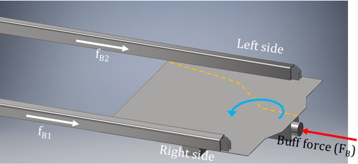
1.21.2 Estimated magnitude of buff force that contributed to structural failure
Given the extent of the structural defects observed in bathtub gondola car DJJX 30478, FEM was also used to estimate the magnitude of the buff force under which the structure could fail (Appendix E).
Modelling of the car-end structures of car DJJX 30156, which was of the same design as DJJX 30478, was also performed, and the results were consistent with the results from the NRC’s compressive end testing (628 kips). This validated the methodology used to determine the failure mechanism on the car and the calculated force exerted on the car during the structural failure.
An FEM for the DJJX 30478 B-end platform structure, which remained intact during the occurrence, was constructed based on the observed state of the car and the defects that were present post-derailment. The FEM determined that buckling of the DJJX 30478 B-end shear plate would have occurred with an applied buff force of approximately 410 kips.
However, an FEM for the DJJX 30478 A-end platform structure could not be properly constructed because much of the shear plate and the entire left-side sill was not recovered, so the exact state of the defects that were present at the time of the accident could not be established with any precision.
1.21.3 Primary structural defect of the Berwick Forge bathtub gondola cars examined
While there were various types of structural defects observed on both subject car DJJX 30478 and car DJJX 30156, of the same design, the reduced thickness and cracking of the shear plate due to corrosion appeared to be the main cause of the significant reduction in the strength of the end platform structures of the cars.
By engineering design, the critical buckling load of the shear plate is dependent on its thickness when other design parameters remain unchanged. When compared with the ACF cars examined, the Berwick Forge bathtub gondola cars were constructed with thinner shear plate material, which made the cars more susceptible to buckling failure, particularly when exposed to corrosion that reduced the thickness of the shear plate.
1.22 TSB laboratory reports
The TSB completed the following laboratory reports in support of this investigation:
- LP176/2019 Dynamics Simulations
- LP177/2019 Structural Failure Analysis of Bathtub Gondola
- LP141/2020 Sarnia Gondola Car Metallurgical Examination Scoping
- LP012/2021 Sarnia Gondola Car Coupon Metallurgical Examination
The TSB contracted the following engineering report in support of this investigation:
- NRC Bathtub Gondola Car Testing Report AST-2020-0009 Rev 1 – Final, Dated 17 September 2020
2.0 Analysis
The accident occurred inside the Canadian National Railway Company (CN) Paul M. Tellier Tunnel under the St. Clair River; the tunnel connects Sarnia, Ontario, Canada, to Port Huron, Michigan, United States (U.S.). The track through the tunnel was in good condition, and there were no track defects present that could be considered causal. The crew of westbound CN freight train M38331-27 (the train) were familiar with the territory and qualified for their respective positions.
For this accident to occur, the car involved had to be in a deteriorated structural state and sufficient in-train forces exceeding the reduced structural strength of the car had to be present. The analysis will focus on the structural failure of bathtub gondola car DJJX 30478, the train crew’s emergency response following the train derailment in the tunnel, train marshalling and in-train forces, freight car regulatory and interchange inspections, the condition of the rolling stock, as well as the multi-jurisdictional agency collaboration while responding to a derailment site that spanned the international border between Canada and the U.S.
2.1 The accident
From the east crest of the tunnel, the throttle remained in idle and the train accelerated by gravitational force on the descending grade of the tunnel until the head-end locomotives arrived at the bottom of the tunnel. Once at the bottom, the locomotive engineer (LE) slowly increased the throttle to notch 3 as the train ascended the grade toward the tunnel’s west portal at Port Huron. While the train was travelling at 44 mph in the tunnel, a train-initiated emergency brake application occurred while the head-end locomotive was at Mile 61.19. The separated head-end portion of the train stopped outside the tunnel at Mile 61.46, while the tail end was outside the tunnel’s east portal in Sarnia.
Unknown to the crew at that time, 46 of the 49 rolling stock, located from lines 51 to 98 inclusive, had derailed and came to rest on both sides of the international border inside the tunnel.
Site examination within the tunnel commenced at the Port Huron portal and headed eastward. The first derailed equipment encountered in the tunnel was the trailing end of car DJJX 19371 (line 51). The next derailed car, DJTX 30049 (line 52), had all wheels derailed and came to rest at Mile 60.85. On the trailing B-end of DJTX 30049, the knuckle and coupler remained intact, and there was no visible impact damage. Behind (east of) DJTX 30049, the south rail had rolled, and there was a separation of 696 feet leading up to the leading A-end of DJJX 30478 (line 53), a bathtub gondola car loaded with scrap steel, at Mile 60.72.
All wheels of DJJX 30478 had derailed, and the A-end of the car was extensively damaged. The A-end left-side end post, side sill, and side sheet had separated from the shear plate and collapsed. The A-end truck was skewed diagonally, and both rails had rolled outward. The car had dug into the roadbed, and the A-end knuckle was broken. The B-end of the car was relatively intact but was surrounded by the scrap steel lading from the car that had been released to the track surface eastward from the B-end of DJJX 30478. Scrap steel was sporadically observed on the ballast along the south side of the tunnel, extending back to about Mile 60.55.
Findings as to causes and contributing factors
The accident occurred when bathtub gondola car DJJX 30478 (line 53), loaded with scrap steel, sustained a structural failure and the A-end left side of the car collapsed, causing the car to derail in the CN Paul M. Tellier tunnel at Mile 60.55, about 425 feet east of the international border between Canada and the U.S., on the Canadian side.
As DJJX 30478 collapsed, the A-end truck became skewed beneath the car, causing both rails to roll outward and derail the trailing cars.
Once the car had collapsed, it dug into the roadbed, and the A-end knuckle failed as the train pulled apart between the trailing end of DJTX 30049 (line 52) and the A-end of DJJX 30478 (line 53), which resulted in the train-initiated emergency brake application.
The derailed cars included dangerous goods (DG) tank car UTLX 95205 (line 68), which was loaded with 94% sulphuric acid (UN1830 Class 8, Packing Group II).
Finding as to causes and contributing factors
During the derailment, the trailing-end stub sill and coupler of covered hopper car VTGX 1238 (line 67) struck and punctured the lower left quadrant of the leading B-end tank head of dangerous goods tank car UTLX 95205 (line 68), releasing an estimated 12 172 U.S. gallons (46 076 L) of sulphuric acid in the tunnel.
2.2 Train crew’s emergency response following a train derailment in a tunnel
As the train derailed, there was an alarm on the rail traffic control display. However, to view the alarm, the rail traffic controller (RTC) had to open a different computer window to see the details.
Once the separated head-end portion of the train came to a stop, the train crew made an emergency broadcast on the emergency radio channel as prescribed by the Canadian Rail Operating Rules (CROR) Rule 102, to report the emergency brake application to the RTC. The crew then requested that the lights and ventilation fans be turned on in the tunnel. However, at that time, the RTC had not yet determined the nature of the alarm and did not inform the crew about the alarm. The crew then conducted a job briefing during which the contents of the train, including the DG tank car of sulphuric acid, were discussed.
Soon after the briefing, the conductor, who was not equipped with respiratory protection, exited the locomotive cab to enter the tunnel and inspect the train, in accordance with CN company instructions. The CN instructions in place at the time did not require the train crew to wait for RTC confirmation that it was safe to enter the tunnel following a derailment.
Finding as to risk
The absence of a company requirement for a train crew to wait for confirmation that it is safe to enter a tunnel to conduct a train inspection following an occurrence involving dangerous goods presents a risk that crew members may be unnecessarily exposed to a hazardous situation.
About 5 minutes after the crew had made the emergency call, the RTC contacted the LE and the assistant conductor in the locomotive cab and informed them that the toxic gas alarm in the tunnel had activated. The RTC then asked them whether the direction in which the exhaust from the fans was blowing mattered, and the crew responded that it did not, as long as the fans were blowing.
Finding as to risk
When there is potential for dangerous goods to be released in a tunnel during a derailment, if the tunnel ventilation fans are exhausted toward personnel who enter the tunnel without respiratory protection, there is an increased risk of adverse consequences if they are exposed to dangerous goods.
2.2.1 Toxic gas alarm in the tunnel
The tunnel was equipped with toxic gas monitors and an alarm system that provided continuous monitoring to warn of a DG release. The system was also designed to activate an alarm if the equipment malfunctioned or was damaged as the result of a derailment and became inoperable. However, the RTC display for the alarm system only identified if the system was activated and did not provide feedback on the state of the system. As a result, there was no way for the RTC to confirm whether there was a toxic gas alarm or if the system had malfunctioned or was damaged.
After the conductor inspected the head end of the train west of the tunnel, he arrived at the Port Huron portal. He heard the ventilation fans operating but noticed that the tunnel lights were still off.
The RTC subsequently contacted the LE and the assistant conductor, informed them that the toxic gas alarm in the tunnel had activated, and further instructed them not to enter the tunnel. It had been assumed that exhaust from the distributed power (DP) remote locomotive was the likely source of the alarm without seeking confirmation. After the discussion, the lights were still off and the east-end fans were exhausting westward toward the conductor as he entered the tunnel without any respiratory protection. Since the conductor had already entered the tunnel, the RTC, LE, and assistant conductor immediately attempted to contact the conductor by radio but were unable to establish communication with him. At the time, they were unaware that the radio repeater system in the tunnel had been damaged by the derailment. Subsequently, the assistant conductor exited the locomotive cab to look for the conductor and observed the conductor safely exiting the tunnel.
Finding as to risk
If a toxic gas alarm activates following a derailment involving dangerous goods in a tunnel, and railway employees assume the source of the activation without further confirmation, there is an increased risk that an employee will be exposed to dangerous goods, with a commensurate risk of serious injury.
2.3 Jurisdiction
This was a unique event involving multiple Canadian and U.S. agencies responding to a rail accident that occurred in the vicinity of an international border where it took several days to establish jurisdiction.
The tunnel crosses the Canada–U.S. border. Since the derailed cars blocked access to the border within the tunnel, it was unclear if the initial point of derailment (POD) was on the Canadian or the U.S. side of the border. The accident was initially reported to the TSB which, in turn, notified the U.S. National Transportation Safety Board (NTSB). Subsequently, the TSB, the NTSB, and the Federal Railroad Administration (FRA) each deployed a team of investigators to the site.
The various site examination and investigative activities took place over a period of 9 days from 28 June 2019 to 06 July 2019. Throughout the deployment, the joint TSB and NTSB team managed and coordinated all investigation activities among the team members and other responding agencies when required.
The investigation teams determined that the train-initiated emergency brake application indicated a train pull-apart that occurred at, or near, the initial POD. To establish jurisdiction, the TSB, NTSB, FRA, and CN each completed separate analyses of locomotive event recorder (LER) and DP log data. Although each party used slightly different methodologies and assumptions, each of the analyses confirmed that the train-initiated emergency brake application occurred as a result of a train separation between cars DJTX 30049 (line 52) and DJJX 30478 (line 53) about 400 feet to 600 feet east of the border, on the Canadian side.
Findings: Other
Analyses of data recovered from the LERs and DP logs confirmed that the train-initiated emergency brake application occurred as a result of a train separation between the 52nd and 53rd cars on the Canadian side of the border, so the TSB assumed responsibility for the accident investigation.
The deployed TSB and NTSB teams worked seamlessly and effectively together to accomplish the various investigation tasks on both sides of the border, under sometimes challenging circumstances.
2.4 Structural failure of DJJX 30478
The leading A-end of car DJJX 30478 (line 53) was extensively damaged and collapsed. DJJX 30478 was likely the first car to derail as the A-end of the car sustained structural failure while travelling in the tunnel. At the time of the accident, DJJX 30478 exhibited a number of pre-existing defects that likely contributed to its reduced structural integrity. The structural defects included the following:
- The steel reinforcement u-channels, which were installed when the car was modified to carry scrap steel, were extensively corroded, and the bottom portion of the u-channels was missing.
- The observed condition of the welds that secured the u-channels to the tub indicated that this condition had likely existed for some time prior to the accident.
- The car was heavily corroded and exhibited numerous cracks in the welds that secured both shear plates to the stub sills, car body bolsters, and side sills.
- There was extensive thinning of both shear plates due to corrosion that had occurred prior to the occurrence.
- The top chords and many of the side posts were buckled.
- Numerous side sheets, end sheets, and tub sections were ruptured and compromised.
Finding as to causes and contributing factors
The structural defects that were present in the shear plates, stub sills, car body bolsters, and side sills of car DJJX 30478 negatively affected the ability of the car to withstand in-train forces.
2.4.1 Shear plate thickness
While the Berwick Forge & Fabrication Corporation (Berwick Forge) and ACF Industries Inc. (ACF) bathtub gondola cars subjected to compression testing were similar in appearance, there were several differences in their structure. Compared to the ACF cars, the Berwick Forge cars were constructed with slightly smaller side sills and thinner shear plate material. Specifically, the original shear plate thickness of the ACF cars was 0.44 inches while the Berwick Forge cars original shear plate thickness was 0.31 inches.
Given the extensive corrosion and shear plate failure observed in DJJX 30478, the measured average percent reduction of shear plate thickness for the ACF and Berwick Forge bathtub gondola cars were compared. The average percent reduction in the thickness of shear plates was 12% for the ACF cars and 29.5% for the Berwick Forge cars.
By engineering design, the critical buckling load of the shear plate, when subjected to buff force (i.e. in compression), is dependent on its thickness when other design parameters remain unchanged. While there were various types of structural defects observed on both Berwick Forge cars (subject car DJJX 30478 and car DJJX 30156 of the same design), the reduced thickness and cracking of the shear plate due to corrosion appeared to be the main cause for the significant reduction in the strength of the end platform structures of the cars.
Findings as to causes and contributing factors
Berwick Forge bathtub gondola cars were constructed with thinner shear plate material than the ACF cars examined, which made the Berwick Forge cars more susceptible to buckling failure, particularly when exposed to corrosion throughout their service life, further reducing the thickness of the shear plates.
2.5 Compressive end load testing of DJJX bathtub gondola cars
The Association of American Railroads (AAR) Manual of Standards and Recommended Practices (MSRP), Specification M-1001, sets forth the minimum requirements for the design and construction of new freight cars for use in Canada and the U.S. Freight cars constructed in accordance with the AAR MSRP after 01 July 1974 are qualified for 50 years of service without any need for re-qualification, provided they met the original AAR design criteria, which include compressive end load testing.
The TSB contracted the National Research Council Canada (NRC) to perform compressive end load testing of the 3 bathtub gondola cars selected from CN’s Port Huron Yard. Given their worn state after 40 years of service, the testing assessed the ability of these 3 bathtub gondola cars to meet the longitudinal compressive static load required by the AAR MSRP, Specification M-1001.
2.5.1 Results of compressive end load testing
The test procedure required that a horizontal compressive static load of 1 000 000 pounds of force be applied at the centreline of the draft system and held for a minimum of 60 seconds before releasing the pressure. This procedure must be completed 3 consecutive times without any structural failure for a car to pass the test.
While the 2 ACF cars passed the test, the Berwick Forge car DJJX 30156 (line 13), of the same design as DJJX 30478, experienced structural failure at about 628 kips (628 000 pounds of force) during the first force application. As a result, the test could not be repeated. Furthermore, the force displacement graph for the test exhibited a change in slope at about 450 kips (450 000 pounds of force), which indicated that DJJX 30156 was behaving non-elastically prior to failure.
The 2 bathtub gondola cars manufactured by Berwick Forge—DJJX 30478, which failed in the tunnel, and DJJX 30156, which failed the compressive end load testing—each sustained structural failure in a similar area of the A-end left side.
2.6 Finite element modelling
Given the presence of the defects that compromised the structural integrity of DJJX 30478, a finite element model (FEM) of the bathtub gondola platform was constructed and analyzed to understand the type and magnitude of the forces required to cause the A-end structural failure.
By design, the buff/draft load path for bathtub gondola cars is from the stub sill and body bolster to the shear plate, then from the shear plate to the side sills. During train operation, the side sills transfer the buff and draft loads from one end of the car to the other.
While several forces were acting on the car at the time of the accident, FEM failure analysis determined that, when the car DJJX 30478 A-end platform was subjected to in-train buff force, a large amount of torque was produced to the right of the A-end platform fracture line. This caused the A-end platform structure to twist or rotate inward, which was consistent with site observations and the examination of the car wreckage.
Finding as to causes and contributing factors
Finite element modelling and failure analysis confirmed that, given the presence of the defects that compromised the structural integrity of bathtub gondola car DJJX 30478, the in-train buff (compressive) force exerted on the car resulted in the A-end structural failure that led to the derailment sequence.
2.6.1 Magnitude of buff force that contributed to structural failure
Given the extent of the structural defects observed in bathtub gondola car DJJX 30478, the FEM was also used to estimate the magnitude of the buff force under which the structure could fail.
Modelling of the car end structures of car DJJX 30156, of the same design as DJJX 30478, was also performed, and the results were consistent with the NRC compressive end testing results (628 kips), which agreed with the results of the FEM.
An FEM for the DJJX 30478 A-end platform structure could not be constructed because much of the structure was not recovered so the exact state of the defects that were present could not be established. However, an FEM for the DJJX 30478 B-end platform structure was constructed based on the observed state of the car and the defects that were present post derailment. The FEM analysis determined that buckling of the DJJX 30478 B-end shear plate would have occurred with an applied buff force of approximately 410 kips.
While the original car design approval was contingent on demonstrating that it met the AAR compressive load test standard of 1000 kips (1 000 000 pounds of force), the FEM failure analysis of the intact B-end of subject car DJJX 30478 estimated that structural failure could occur at approximately 410 kips. When compared to the original car design, this represents a significant reduction (approximately 59%) in overall strength of the car due to the presence of the observed structural defects in the B-end of DJJX 30478.
Findings as to causes and contributing factors
The FEM failure analysis of the intact B-end of DJJX 30478 calculated that structural failure would occur when subjected to a buff force of approximately 410 kips, which, when compared with the AAR design requirement of 1000 kips, represents a 59% reduction in the design strength of the car due to the presence of the observed structural defects.
Since the B-end of DJJX 30478 remained intact as the A-end sustained structural failure in the tunnel, the buff force that was acting on the A-end of DJJX 30478 at the time of occurrence must have been less than those forces acting on its B-end.
2.7 Dynamics simulations
Departing Sarnia, the train was marshalled with a block of lighter, loaded, autorack cars equipped with long travel end-of-car cushioning devices (EOCCDs) located from line 70 to line 97. Since the DP remote locomotive was located between line 81 and line 82, there were 12 lighter-weight loaded autorack cars located ahead of, and another 17 lighter-weight loaded autorack cars behind, the DP remote locomotive. The remaining tail-end cars on the train (line 98 to line 140) were primarily heavily loaded cars. The train had 31.1% of its tonnage in the rear 25% of the train, which made the train borderline tail-end heavy.
Site examination identified that car DJJX 30478 (line 53) was the first car to derail as the A-end of the car sustained structural failure when subjected to in-train buff (compressive) force while travelling in the tunnel. The bathtub gondola car DJJX 30478 was in a deteriorated state at the time of the accident and, consequently, was not able to withstand the in-train buff force.
In order to determine the magnitude of the maximum longitudinal buff force acting on car DJJX 30478 (line 53), the TSB laboratory conducted a series of train dynamics simulations. The Train Energy Dynamic Simulation (TEDS) software was used to assess the in-train forces associated with the operation of the occurrence train as well as alternative train configurations and train-handling options. The maximum in-train buff force at the first derailed car (DJJX 30478) immediately before the train-initiated emergency brake application was calculated to be approximately 388 kips.
The leading A-end of car DJJX 30478 (line 53) therefore collapsed and failed because of its deteriorated condition when subjected to a buff force of up to approximately 388 kips, which was a reduction of approximately 61% of the original design strength of the car.
Finding as to causes and contributing factors
Dynamics simulations determined that the A-end of bathtub gondola car DJJX 30478 collapsed and failed in the tunnel when subjected to an in-train buff force of up to approximately 388 kips, which represents a 61% reduction in the original design strength of the car due to its deteriorated condition.
2.7.1 Placement of the autorack cars in the train
The AAR Train Make-Up Manual notes that cars equipped with EOCCDs will add to train slack and can greatly increase in-train forces. In general, cuts of empty cars equipped with EOCCDs should not be placed ahead of large cuts of loaded cars equipped with standard draft gears for trains operating on main track.
Although the train departing Sarnia complied with current CN marshalling guidelines, it was borderline tail-end heavy, since 31.1% of its tonnage was located in the rear 25% of the train. Furthermore, the tail-end tonnage also trailed behind a block of 29 lighter-weight loaded autorack cars equipped with long travel hydraulic EOCCDs.
During the dynamics simulation of the occurrence consist, the calculated buff forces exerted on the car increased from 200 to 388 kips over a distance of approximately 1279 feet in about 22 seconds before the air brakes applied in emergency. The car would have failed structurally during this interval and likely travelled for some distance in a buff state before the air hoses subsequently separated and triggered the emergency brake application. The investigation could therefore not determine the exact force at which the structural failure occurred.
However, additional dynamics simulations demonstrated that relocating the block of 29 lighter-weight loaded autorack cars equipped with EOCCDs to the end of the occurrence train, and behind the 31.1% of the tail-end tonnage that was added to the train in Sarnia, would have reduced the maximum in-train buff force on car DJJX 30478 (line 53) to about 235 kips.
Finding: Other
TSB simulations calculated that the in-train buff force on the occurrence car could have been reduced from approximately 388 kips to 235 kips with the block of lighter-weight autorack cars marshalled at the tail-end of the train.
2.7.2 Placement of distributed power remote locomotives and train handling
According to CN requirements, the train departing Sarnia should have had the DP remote locomotive placed between lines 114 and 115 of the train. However, in this occurrence, the train DP remote locomotive was placed between line 81 and line 82.
The simulations also demonstrated that, if the train DP remote locomotive was relocated to between lines 114 and 115 in accordance with CN guidelines, the actual train handling would have produced a slightly higher maximum in-train force of 414 kips on car DJJX 30478. If the modified CN train-handling instructions were followed, the maximum in-train force on car DJJX 30478 would have been further increased to 426 kips.
Finding: Other
While the DP remote locomotive placement between line 81 and line 82 did not comply with CN DP remote locomotive placement criteria, it did not play a role in the accident.
The LE generally adhered to CN train-handling guidelines while approaching the tunnel and descending to the bottom of the tunnel. After reaching the bottom of the tunnel, all 3 locomotives were operated in a synchronized fashion, as per the Strathroy Subdivision Timetable No. 43 requirements.
This differed slightly from the CN train-handling instructions that had been modified in October 2016 and were in force at the time of the accident. The modified train-handling instructions required the DP remote locomotive throttle to be in idle, or in a throttle position 2 levels lower than the head-end locomotives, as the head-end locomotives ascended the grade.
In this case, the actual train handling could have generated an estimated maximum in-train buff force of 388 kips. However, for the occurrence train, had the LE followed the modified CN train-handling requirements in force at the time of the accident, it could have resulted in an estimated maximum in-train force of 420 kips on car DJJX 30478.
Finding: Other
Although the occurrence train handling differed from the CN train-handling instructions for the tunnel, train handling did not play a role in the accident.
2.8 Bathtub gondola car DJJX 30478 transition from coal to scrap steel service
Before bathtub gondola cars were developed, flat-bottomed gondola cars were used to transport resource commodities. These cars were loaded and unloaded from the open top by mechanical means such as backhoes. Flat-bottomed gondola cars have a continuous centre sill extending the length of the car, heavy steel transverse cross-bearers and steel stringers that secure the centre sill to the side sills, and a heavy floor secured to the underframe. The underframe and floor provided a robust platform for bulk lading but also added a substantial amount of weight to the car which limited the amount of lading that could be carried.
In 1973, the bathtub gondola car design was introduced in the rail industry. This lighter-weight car was specifically designed for the uniform loading of bulk granular lading such as coal. With the bathtub gondola design, longitudinal in-train forces exerted on the car stub centre sill are transmitted through the shear plate and side sills along the length of the car to the other end, bypassing the tub and eliminating the need for a conventional underframe. As originally designed, the cars were also equipped with reinforcement crossbars (2 upper and 2 lower) that were secured to side sills and top chords of the car interior to provide lateral stability.
When loaded with coal, the granular lading was equally distributed throughout the car and the pressure from the load stabilized the tub so that it did not require reinforcing. The lack of a full steel underframe resulted in a lighter-weight car with a 5-ton greater load capacity than flat-bottomed gondola cars.
The Berwick Forge–built bathtub gondola car that failed in the tunnel was initially in utility coal service for about 34 years. In 2012, the car was retired from coal service and purchased by the David J. Joseph Company Rail Equipment Group (DJJ Co.), as part of a larger purchase of 1650 similar cars with the intention of using them in scrap steel service, and renumbered as DJJX 30478.
Since the Berwick Forge bathtub gondola cars originally had crossbars that obstructed loading of scrap steel, DJJ Co. received AAR approval for a modification; all 1650 cars were modified by replacing the 4 reinforcement crossbars with 2 large steel u-channels fabricated inside the car to compensate for the structural change as well as by reinforcing the tub and securing it to the side sills and side sheets of the car.
It is not uncommon to find cars of this type and vintage that have transitioned into maintenance-of-way or scrap steel service and there are no industry restrictions on how these cars may be utilized. As of 14 August 2019, DJJ Co. had a total of 1331 such bathtub gondolas remaining in scrap steel service, 692 of which were built by Berwick Forge.
The Berwick Forge bathtub gondola cars had a lighter design that incorporated a parabolic curved bottom steel sheet (tub). The cars were built specifically for transporting granular lading. Once the cars were introduced into other types of service (i.e. scrap steel and railway ties), the loading was no longer uniform and the structural members were exposed to uneven loading for which they were not designed.
Scrap steel, in particular, is recognized by the industry as a much more demanding service than transporting granular lading. Scrap steel is loaded using a crane or backhoe that picks up the material, sometimes as loose pieces of steel and sometimes as large, compressed blocks of steel, and drops it into the car. As the car fills up, crane operators sometimes “tamp” the scrap steel to even out and compress the load so that more material can be loaded. A similar process is used for unloading steel from the car.
In the case of Berwick Forge–built bathtub gondola car DJJX 30478, repeated scrap steel loading and unloading also resulted in the destruction of the structural elements that DJJ Co. had added to the car interior to replace the reinforcement crossbars, which further compromised the car’s structural integrity.
When internal structural modifications are required for open-top freight cars in extended service that transition to a commodity service they were not designed for, the process for loading and unloading of the new commodity and how that may adversely affect both the original structure and the modified structure, must be considered. In these cases, any approval process for structural modification should also include a requirement for periodic inspection of the car’s internal and external structure in order to ensure it maintains its structural integrity. In the absence of such a requirement, car owners could also take the initiative to periodically inspect their modified equipment for emerging structural defects.
Finding as to causes and contributing factors
Bathtub gondola car DJJX 30478, built by Berwick Forge, was used in a demanding service for which the car was not originally designed, and there was no industry or regulatory requirement to periodically conduct a full inspection of the car to ensure it maintained its structural integrity. As a result, its structural integrity deteriorated and this deterioration was not identified prior to the accident.
2.9 Interchange of freight cars with structural deficiencies
Interchange occurs when a railway accepts a freight car for service on its line, from another railway, at common line points that include the Canada/U.S. border. Efficient, seamless railway operation between Canada and the U.S. has become essential to the economies of both countries. As such, the regulatory requirements of the Transport Canada (TC)-approved Railway Freight Car Inspection and Safety Rules 2014 (freight car safety rules) and the U.S. FRA CFR, Title 49, Volume 4, Part 215—Railroad Freight Car Safety Standards (2011) (freight car safety standards) are virtually identical.
The Canadian freight car safety rules and the U.S. freight car safety standards establish the minimum safety criteria for freight cars operated by federally regulated railways in each country. Both the rules and the standards have provisions that permit freight cars with defects to be moved to a location for repair. However, neither the Canadian freight car safety rules nor the U.S. freight car safety standards contain limits for damage to significant freight car structure, such as buckled side posts; ruptured side sheets, end sheets, and tub sections; negative side sill camber; buckled top chords; or extensive cracking and corrosion.
In addition, at the time of the accident, the 2019 Association of American Railroads (AAR) Field Manual of the AAR Interchange Rules (AAR Interchange Rules) governed the interchange of freight cars between railways. The AAR Interchange Rules are revised, improved upon and re-issued every year. Railways and car owners agree to follow the AAR Interchange Rules, and other applicable AAR manuals and publications, if they operate or own equipment that may be interchanged.
2.9.1 Field Manual of the AAR Interchange Rules
The 2019 AAR Interchange Rules govern matters pertaining to the interchange of freight car traffic between railways and define responsibility for the cost of freight car repairs due to regular wear and tear and/or the implementation of safety improvements in accordance with AAR standards. The rules detail the applicable condemning limits for all car parts and conditions. Once these limits are either reached or exceeded, repairs are warranted. With regard to the structure of bathtub gondola cars:
- Rule 57 applied to centre sills but had no information on stub sills or stub sill defects that required attention.
- Rule 58 applied to side sills but had no guidance on side sill defects that required attention.
- Rule 89 outlined conditions governing the delivery and acceptance of cars in interchange between railways. The rule noted that a car with stub centre sills extending through the body bolster and branching into 2 or more side sills, which had a side sill broken and/or bent in excess of 1½ inches between the body bolsters, was prohibited in interchange.
2.9.2 National Research Council Canada visual inspections and pre-test measurements
The NRC visual inspections of the ACF-built empty bathtub gondola cars DJJX 950782 (line 1) and DJJX 950965 (line 50), as well as the Berwick Forge–built empty car DJJX 30156 (line 13), prior to compressive end loading testing identified extensive damage on each car. Each of the 3 cars showed signs of
- buckled side posts;
- ruptured side sheets, end sheets, and tub sections;
- negative side sill camber;
- buckled top chords; or
- extensive cracking and corrosion.
However, none of the damage observed was condemnable under either the Canadian freight car safety rules or U.S. freight car safety standards.
To supplement the visual inspections, the NRC conducted pre-test and post-test measurements on the 3 empty cars for top chord (frame) straightness and side sill camber (sag). In each case, the measured pre-test side sill camber, for at least 1 side sill of each car, exceeded the AAR Interchange RulesRule 89 limit of 1½ inches. This means that, technically, the ACF-built bathtub gondola cars DJJX 950782 (line 1) and DJJX 950965 (line 50), as well as the Berwick Forge–built bathtub gondola car DJJX 30156 (line 13), should have been prohibited in interchange. Since the Berwick Forge–built DJJX 30478 (line 53) failed in the tunnel and DJJX 30156 (line 13) did not, it is likely that DJJX 30478 was in worse condition than the 3 subject cars tested, yet it was also still allowed to remain in service.
2.9.3 Interchange
At the time of its failure in the tunnel, bathtub gondola car DJJX 30478 was in a severely deteriorated condition and exhibited a number of pre-existing defects that contributed to its reduced structural integrity. Visual examination of the car determined that the defects were not recent and had developed over a period of time prior to the accident.
Despite its deteriorated condition, DJJX 30478 travelled frequently within, and between, Canada and the U.S. and was interchanged between railways 16 times in the 6 months prior to the accident.
In the 3 months prior to the accident, DJJX 30478 received 24 certified car inspections conducted at various CN line points, had numerous pull-by inspections, and traversed multiple wayside inspection systems, with no significant defects noted. In the year prior to the accident, the car only required routine maintenance.
Up until 2012, interchange between railways required that certified car inspectors from the handling railway physically inspect freight cars against the AAR Interchange Rules prior to interchange. Similarly, the receiving railway had its certified car inspectors inspect the freight cars against the AAR Interchange Rules before accepting the freight cars for service. During these interchange inspections, freight cars identified with AAR condemnable defects were prohibited from interchange.
However, in 2012, the Canadian freight car safety rules were modified, and an interchange inspection was no longer required at an interchange point or when crossing the border. The interchange inspection was replaced by a safety inspection conducted in accordance with either the Canadian freight car safety rules or the U.S. freight car safety standards.
At least 1 side sill of each of the 3 bathtub gondola cars recorded negative side sill camber in excess of the AAR Interchange Rules Rule 89 limit (1½ inches). It is likely that DJJX 30478 was in worse condition than the 3 bathtub gondola cars tested. In these 4 cases, had an interchange inspection been performed, the cars would have exceeded the limits of the AAR Interchange Rules due to excess negative side sill camber. But freight car AAR interchange inspections no longer applied because they had been replaced with safety inspections that did not identify negative side sill camber as a safety defect.
Finding as to causes and contributing factors
Four of the DJJX bathtub gondola cars on the train exhibited numerous structural deficiencies, which included a negative side sill camber in excess of the AAR Interchange Rule 89 limit of 1½ inches. However, since neither the Transport Canada-approved freight car safety rules nor the U.S. freight car safety standards identify the structural deficiencies as safety defects, the 4 cars remained in service in a deteriorated condition without restriction until car DJJX 30478 failed in the tunnel.
Freight car safety rules and standards do not identify buckled side posts; ruptured side sheets, end sheets, and tub sections; negative side sill camber; buckled top chords; or extensive cracking and corrosion as safety defects. This demonstrates that the Canadian freight car safety rules and the U.S. freight car safety standards are not sufficient to ensure the safe operation of freight cars in all cases.
Finding as to risk
If freight car safety rules and standards do not identify structural deficiencies as safety defects, there is an increased risk that an aging freight car in a deteriorated condition may sustain structural failure while in service and cause a derailment.
2.10 Universal Machine Language Equipment Register
Following the CN derailment in the tunnel and the examination of the 5 similar bathtub gondola cars at Port Huron, CN researched the Universal Machine Language Equipment Register (UMLER) system and identified about 2130 cars of similar type and vintage that were being used in scrap steel service in North America.
By 16 September 2019, CN had inspected 416 of the 2130 cars identified as they came onto CN lines and found 36% of the cars (149 out of 416) had defects according to the AAR Interchange Rules.
However, there were challenges with being able to accurately identify the number of these car types, built by the same manufacturer, that remained in service. Although UMLER contains detailed specifications for each car registered, there are gaps in some of the information recorded. Specifically, data fields in UMLER may not be filled consistently, may be confidential to the car owner, or may not be recorded at all.
The absence of this information in UMLER made it difficult to identify and locate potentially defective freight cars with any consistency. Consequently, there might have been even more than 2130 cars of this type and vintage that were being used in scrap steel service throughout North America.
Finding as to risk
Because some rail car information in the UMLER system is not consistently recorded or displayed to all the users of the system, the ability to identify all cars with potential defects to be recalled for inspection would be hindered, increasing the risk that a component or structural failure in one of these cars will cause an accident.
3.0 Findings
3.1 Findings as to causes and contributing factors
These are conditions, acts or safety deficiencies that were found to have caused or contributed to this occurrence.
- The accident occurred when bathtub gondola car DJJX 30478 (line 53), loaded with scrap steel, sustained a structural failure and the A-end left side of the car collapsed, causing the car to derail in the Canadian National Railway Company Paul M. Tellier tunnel at Mile 60.55, about 425 feet east of the international border between Canada and the United States, on the Canadian side.
- As DJJX 30478 collapsed, the A-end truck became skewed beneath the car, causing both rails to roll outward and derail the trailing cars.
- Once the car had collapsed, it dug into the roadbed, and the A-end knuckle failed as the train pulled apart between the trailing end of DJTX 30049 (line 52) and the A-end of DJJX 30478 (line 53), which resulted in the train-initiated emergency brake application.
- During the derailment, the trailing-end stub sill and coupler of covered hopper car VTGX 1238 (line 67) struck and punctured the lower left quadrant of the leading B-end tank head of dangerous goods tank car UTLX 95205 (line 68), releasing an estimated 12 172 U.S. gallons (46 076 L) of sulphuric acid in the tunnel.
- The structural defects that were present in the shear plates, stub sills, car body bolsters, and side sills of car DJJX 30478 negatively affected the ability of the car to withstand in-train forces.
- Berwick Forge & Fabricating Corporation (Berwick Forge) bathtub gondola cars were constructed with thinner shear plate material than the ACF Industries Inc. cars examined, which made the Berwick Forge cars more susceptible to buckling failure, particularly when exposed to corrosion throughout their service life, further reducing the thickness of the shear plates.
- Finite element modelling and failure analysis confirmed that, given the presence of the defects that compromised the structural integrity of bathtub gondola car DJJX 30478, the in-train buff (compressive) force exerted on the car resulted in the A-end structural failure that led to the derailment sequence.
- The finite element modelling failure analysis of the intact B-end of DJJX 30478 calculated that structural failure would occur when subjected to a buff force of approximately 410 kips, which, when compared with the Association of American Railroads design requirement of 1000 kips, represents a 59% reduction in the design strength of the car due to the presence of the observed structural defects.
- Since the B-end of DJJX 30478 remained intact as the A-end sustained structural failure in the tunnel, the buff force that was acting on the A-end of DJJX 30478 at the time of occurrence must have been less than those forces acting on its B-end.
- Dynamics simulations determined that the A-end of bathtub gondola car DJJX 30478 collapsed and failed in the tunnel when subjected to an in-train buff force of up to approximately 388 kips, which represents a 61% reduction in the original design strength of the car due to its deteriorated condition.
- Bathtub gondola car DJJX 30478, built by Berwick Forge & Fabricating Corporation, was used in a demanding service for which the car was not originally designed, and there was no industry or regulatory requirement to periodically conduct a full inspection of the car to ensure it maintained its structural integrity. As a result, its structural integrity deteriorated and this deterioration was not identified prior to the accident.
- Four of the DJJX bathtub gondola cars on the train exhibited numerous structural deficiencies, which included a negative side sill camber in excess of the Association of American Railroads interchange Rule 89 limit of 1½ inches. However, since neither the Transport Canada-approved Railway Freight Car Inspection and Safety Rules nor the United States Federal Railroad Administration Code of Federal Regulations, Title 49, Volume 4, Part 215—Railroad Freight Car Safety Standards identify the structural deficiencies as safety defects, the 4 cars remained in service in a deteriorated condition without restriction until car DJJX 30478 failed in the tunnel.
3.2 Findings as to risk
These are conditions, unsafe acts or safety deficiencies that were found not to be a factor in this occurrence but could have adverse consequences in future occurrences.
- The absence of a company requirement for a train crew to wait for confirmation that it is safe to enter a tunnel to conduct a train inspection following an occurrence involving dangerous goods presents a risk that crew members may be unnecessarily exposed to a hazardous situation.
- When there is potential for dangerous goods to be released in a tunnel during a derailment, if the tunnel ventilation fans are exhausted toward personnel who enter the tunnel without respiratory protection, there is an increased risk of adverse consequences if they are exposed to dangerous goods.
- If a toxic gas alarm activates following a derailment involving dangerous goods in a tunnel, and railway employees assume the source of the activation without further confirmation, there is an increased risk that an employee will be exposed to dangerous goods, with a commensurate risk of serious injury.
- If freight car safety rules and standards do not identify structural deficiencies as safety defects, there is an increased risk that an aging freight car in a deteriorated condition may sustain structural failure while in service and cause a derailment.
- Because some rail car information in the UMLER system is not consistently recorded or displayed to all the users of the system, the ability to identify all cars with potential defects to be recalled for inspection would be hindered, increasing the risk that a component or structural failure in one of these cars will cause an accident.
3.3 Other findings
These items could enhance safety, resolve an issue of controversy, or provide a data point for future safety studies.
- The emergency response unified command structure worked well and the measures put in place to protect responders, the public and the environment, as part of emergency response and site mitigation activities, were effective.
- Analyses of data recovered from the locomotive event recorders and distributed power logs confirmed that the train-initiated emergency brake application occurred as a result of a train separation between the 52nd and 53rd cars on the Canadian side of the border, so the Transportation Safety Board of Canada assumed responsibility for the accident investigation.
- The deployed Transportation Safety Board of Canada and National Transportation Safety Board teams worked seamlessly and effectively together to accomplish the various investigation tasks on both sides of the border, under sometimes challenging circumstances.
- Transportation Safety Board of Canada simulations calculated that the in-train buff force on the occurrence car could have been reduced from approximately 388 kips to 235 kips with the block of lighter-weight autorack cars marshalled at the tail-end of the train.
- While the distributed power remote locomotive placement between line 81 and line 82 did not comply with Canadian National Railway Company distributed power remote locomotive placement criteria, it did not play a role in the accident.
- Although the occurrence train handling differed from the Canadian National Railway Company train-handling instructions for the tunnel, train handling did not play a role in the accident.
4.0 Safety action
4.1 Safety action taken
4.1.1 Transportation Safety Board of Canada
Following this accident, the Transportation Safety Board of Canada (TSB) issued Rail Safety Advisories (RSAs) 08/19 and 06/20 to Transport Canada (TC). In addition, RSAs 09/19 and 07/20 were issued to TC and the United States (U.S.) Federal Railroad Administration (FRA).
4.1.1.1 Rail Safety Advisory 08/19 – Train inspection following a derailment with dangerous goods in a tunnel
On 19 August 2019, the TSB issued RSA 08/19. The RSA noted that, following the derailment, the crew followed the Canadian National Railway Company (CN) emergency procedures that were in place at the time of the accident. The conductor entered the tunnel to inspect the train while the locomotive engineer and assistant conductor remained in the locomotive cab. About 10 minutes later, the rail traffic controller (RTC) advised the train crew that the toxic gas alarm in the tunnel had activated and instructed the crew members not to enter the tunnel. Although the conductor was unaware that the toxic gas alarm had activated when he entered the tunnel, he emerged from it without injury.
The RSA identified that CN had no specific instructions or guidance relating to the need for a train crew to wait for RTC confirmation that it was safe to enter a tunnel (or other similar installations) before conducting a train inspection following a derailment. Furthermore, the RSA suggested that TC may wish to ensure that railways have specific instructions or guidance in its emergency procedures for conducting train inspections following a derailment in a tunnel when dangerous goods are involved.
4.1.1.2 Rail Safety Advisory 09/19 – Potentially defective bathtub gondola cars in scrap iron and steel service
On 16 September 2019, the TSB issued RSA 09/19. The RSA indicated that the A-end of bathtub gondola car DJJX 30478 appeared to have sustained a structural failure when subjected to elevated in-train buff (compressive) forces while travelling in the tunnel. Detailed examination of the car identified a number of pre-existing defects, such as corrosion and cracks up to 24 inches long in the welds that secured the A-end shear plate to the stub sill, car body bolster, and side sills.
Bathtub gondola car DJJX 30478 was manufactured in 1978 by Berwick Forge & Fabricating Corporation (Berwick Forge), which is no longer in business. The car had initially been designed for, and used in, resource commodity service for transporting coal and sulphur. In 2012, the car was purchased by the David J. Joseph Company (DJJ Company) and placed in the more aggressive scrap iron and steel service.
Following the derailment, CN researched the Universal Machine Language Equipment Register (UMLER) system and identified about 2130 cars of similar type and vintage that were being used in scrap iron and steel service in North America. CN inspected 416 of the 2130 cars as they came onto CN lines, and identified defects in 149 of the 416 cars (36%).
The RSA identified that bathtub gondola cars, which are equipped with stub sills and were constructed in the late 1970s and early 1980s, may be susceptible to structural failure, particularly if subjected to elevated in-train buff forces. The RSA suggested that TC and the U.S. FRA may wish to ensure that railways and car owners have procedures in place to identify, inspect, and repair bathtub gondola cars that are equipped with stub sills, particularly those used in scrap iron and steel service, which were constructed in the late 1970s and early 1980s.
4.1.1.3 Rail Safety Advisory 06/20 – Managing in-train forces
On 11 September 2020, the TSB issued RSA 06/20. The RSA identified that the train consisted of 2 head-end locomotives, 1 mid-train distributed power (DP) remote locomotive (between line 81 and line 82), and a total of 140 cars, including 125 loaded cars, 12 empty cars, and 3 residue cars. The train was 9541 feet long and weighed 15 674 tons. It contained a block of lighter, loaded, autorack cars equipped with long travel end-of-car cushioning devices (EOCCDs) located ahead of, and behind, the DP remote locomotive (line 70 to line 97), followed by primarily heavily loaded cars on the tail end (line 98 to line 140).
In this occurrence, the A-end of bathtub gondola car DJJX 30478 appeared to have sustained a structural failure when subjected to an elevated in-train buff (compressive) force while travelling in the tunnel. In order to determine the magnitude of the longitudinal buff forces acting on the leading A-end of the car, the TSB laboratory conducted a series of train dynamics simulations using the Train Energy Dynamic Simulation (TEDS) software, with the following results:
- For the occurrence train, the predicted longitudinal buff force occurring at the leading A-end of car DJJX 30478 (line 53) immediately prior to the train-initiated emergency brake application was approximately 388 kips.Footnote 38
- When the autorack cars were remarshalled to the tail end of the train from their original location ahead of and behind the DP remote locomotive, the predicted maximum in-train buff force at the leading A-end of car DJJX 30478 (line 53) was significantly reduced, to about 235 kips.
The RSA noted that, despite the implementation of company train marshalling business rules, CN continues to experience challenges in its ability to consistently safely manage in-train forces. The RSA suggested that TC may wish to ensure that all railways have adequate practices in place to effectively manage in-train forces.
4.1.1.4 Rail Safety Advisory 07/20 – Structural issues on bathtub gondola cars built by Berwick Forge & Fabricating Corporation
On 11 September 2020, the TSB issued RSA 07/20. The RSA identified that the Association of American Railroads (AAR) Manual of Standards and Recommended Practices (MSRP), Specification M-1001, sets forth the minimum requirements for the design and construction of new freight cars for use in Canada and the U.S. Freight cars constructed after 01 July 1974 are qualified for 50 years of service without any need for re-qualification, provided they meet AAR design criteria, which include compressive end load testing.Footnote 39
Since the cars were qualified for 50 years of service, the TSB contracted the National Research Council Canada (NRC) to perform compressive end load testing on 3 of the 5 bathtub gondola cars removed from the head end of the train following the derailment. Two of the 3 bathtub gondola cars tested were built by ACF Industries Inc. (ACF), while the 3rd car (DJJX 30156) was built by Berwick Forge and was a car of the same design as car DJJX 30478, that failed in the tunnel.
The 2 bathtub gondola cars built by ACF. (line 1 and line 50) each passed the test. However, DJJX 30156 (built by Berwick Forge) experienced structural failure at about 628 000 pounds of force during the first force application. As a result, the test could not be repeated. The force displacement graph for the test exhibited a change in slope at about 450 000 pounds of force, which indicates that the car structure had yielded and behaved non-elastically prior to failure.
The 2 bathtub gondola cars manufactured by Berwick Forge, DJJX 30478 that failed in the tunnel and DJJX 30156 that failed the compressive end load test, each sustained structural failure in the A-end left side of the car. The A-end and B-end shear plates of both Berwick Forge bathtub gondola cars had deteriorated due to corrosion. Shear plate material thickness measurements recorded for both cars determined that the shear plate material experienced reductions in thickness ranging from 33% to 77% at the thinnest locations.
The RSA noted that it was likely that the deterioration of the Berwick Forge-built bathtub gondola car shear plates due to corrosion significantly reduced the buff force load capacity of the Berwick Forge–built car. Although the car was qualified by the AAR for 50 years of service from the time of construction (1978), the deterioration observed in critical areas of the shear plates made these cars susceptible to structural failure before they reached the end of their estimated service life. The RSA suggested that industry regulators may wish to ensure that all bathtub gondola cars built by Berwick Forge that operate in North America are identified, located, and examined to ensure continued safe railway operations.
4.1.2 Transport Canada
4.1.2.1 Train inspection following a derailment with dangerous goods in a tunnel
In response to TSB RSA 08/19, on 05 February 2021, TC provided the following information:
- TC noted that under the Canada Labour Code, Part II, railways are responsible for the health and safety of their employees during an emergency.
- TC summarized some of the actions taken by CN and considered that these actions addressed the issue identified in RSA 08/19.
- TC noted that it has responsibility for the oversight of the Canada Labour Code, Part II, for on-board rail employees. Therefore, on behalf of the Minister of Labour, TC will write to railways to bring this occurrence to their attention so they can review equipment and operating procedures at other tunnels on their network to ensure appropriate safety measures are in place.
- In February 2021, TC wrote to the Railway Association of Canada and the Western Canadian Short Line Railway Association, describing this occurrence and noting that, although no injuries to railway employees occurred in this case, it brought to light the risks to employees of performing train inspections in tunnels. TC recommended that Canadian railways take notice of this potential risk and ensure that its equipment, procedures, and instructions be reviewed and updated, as required, to ensure employee safety.
4.1.2.2 Potentially defective bathtub gondola cars in scrap iron and steel service
In response to TSB RSAs 09/19 and 07/20, on 09 November 2020, TC reported the following:
- TC had been in regular contact with the AAR regarding the issues mentioned in the 2 RSAs.
- The AAR has advised TC that, as of 20 October 2020, 1174 out of the 1650 cars identified in Maintenance Advisory MA-0188, which amounts to slightly more than 70% of the total number of cars identified in the MA, have had the advisory closed.
- TC was continuing to follow up with the AAR to ensure that progress continued to be made and that all of the cars identified in the MA-0188 were inspected.
- Subsequent to the issuance of MA-0188, Early Warning (EW) 5344 for bathtub gondola inspection was created. In June 2021, Railinc/AAR made system changes to the EW application and this issue is now covered under the new Equipment Advisory System - Equipment Instruction (EI) 0017. As of October 2022, the EI had been closed for 975 of the 1266 cars currently assigned to EI 0017. To close the EI, the railway/car owner would have inspected and determined that no structural conditions were present, any conditions found were fixed, or the car was scrapped.
4.1.3 Canadian National Railway Company
In response to TSB RSA 08/19, on 24 September 2019, CN provided the following information:
- The tunnel is equipped with sensors that monitor for toxic gases. Besides gas monitoring, the sensors are also designed to send an alarm when they deactivate as a result of damage that renders the equipment inoperable.
- The tunnel light and fan indications on the RTC screen only provide a visual indication of these systems being activated by the RTC and do not provide feedback on any system fault.
- CN has both RTC procedures and timetable instructions for transportation employees in place respecting emergencies in the Sarnia Tunnel. Since this accident, CN is reviewing its procedures and the design of the alarm system and will be making improvements as deemed necessary.
- After the derailment, as an interim measure, CN issued an operating bulletin which instructed crew members as to who to contact and what actions to take should their movements become disabled within the tunnel.
- By November 2020, CN had installed permanent visual and audible alarms in the tunnel’s portals, which will alert employees to the presence of toxic gases. CN also updated its timetable instructions to reflect the installation and functioning of this equipment.
-
On 01 November 2020, CN issued the Rule 83 (C) Summary Bulletin Nov 2020 – April 2021 which included the Strathroy Subdivision. The bulletin included new tunnel emergency procedures that in the event of an emergency in the tunnel, must be followed:
When a movement is stopped by an emergency application of air brakes entering or exiting the tunnel, an employee must initiate an emergency call, giving identification and location, stating that the movement is stopped in emergency.
Crew members on movements disabled within the tunnel must immediately contact the RTC and be governed by instructions received. Do not enter the tunnel until the RTC confirms it is safe to do so. When inside the tunnel, maintain frequent communication with the locomotive engineer or the RTC. If radio communications fail or become garbled, exit the tunnel immediately.
- Following the derailment, CN researched the UMLER system and identified about 2130 cars of similar type and vintage that were being used in scrap iron and steel service in North America. CN inspected 416 of the 2130 cars as they came onto CN lines, and identified defects in 149 of the 416 cars (36%).
4.1.4 Association of American Railroads
4.1.4.1 AAR Maintenance Advisory 0188 (MA-0188) – Inspection of Bathtub Gondola Cars
On 12 December 2019, the AAR issued MA-0188, which required the inspection of the bathtub gondola cars listed. The cars were required to be stopped once empty and their side sills inspected for the presence of cracks and sagging.
MA-0188 noted that the rail industry has recently incurred several failures of bathtub gondola cars equipped with stub sills that have a distinctive structural V-shape on each end.
Two types of failures have occurred. First, cracks initiated inboard of the body bolster on the side sill have propagated, resulting in separation of the end from the rest of the car. Second, cars of this type have incurred sagging of the side sills, which has led to collapse of the car body.
The AAR Equipment Engineering Committee has called for a maintenance advisory requiring mandatory inspection of these cars for cracks and sagging. Inspections will be at the expense of the car owners, and the cars must be inspected again every 2 years.
4.1.4.2 AAR Early Warning 5344 (EW-5344) – MA-0188 Elevated to EW-5344: Inspection of Bathtub Gondola Cars
On 12 December 2020, the AAR elevated MA-0188 to Early Warning status with the issuance of EW-5344 to the rail industry. EW-5344 essentially maintained and extended the same inspection criteria for the suspect bathtub gondola cars identified in MA-0188.
4.1.4.3 AAR Maintenance Advisory 0198 (MA-0198) – Inspection of Bathtub Gondola Cars
On 02 April 2021, the AAR issued MA-0198. This MA follows MA-0188 and EW-5344 and includes the same content and inspection guidelines. MA-0188 had escalated to Early Warning status under EW-5344, and just over 400 cars that had not yet been inspected were moved into the Early Warning. The remaining cars that have not been inspected, now approximately 280, were moved into this advisory, along with additional cars that the AAR has recently determined to be of the same construction. The MA remained in force until the release of a new advisory system.
In June 2021, the Railinc Maintenance Advisory and Early Warning systems were superseded by a more advanced Equipment Advisory system. The Berwick-Forge cars were migrated to Equipment Instruction El-0017 and must be inspected every 2 years. Cars on the list are automatically prohibited from interchange under the Field Manual of the AAR Interchange Rules (AAR Interchange Rules) unless they have been inspected within the 2-year timeframe and determined to be free from the specified defects. The process will repeat every 2 years for each car on the list.
The AAR Equipment Engineering Committee has identified these cars and developed the strategy to have them inspected per the MAs, EWs, and the current El-0017. Some of these cars have been designated as maintenance-of-way equipment and therefore not permitted in interchange service. Many have reached 50 years of age and have been removed from service. Hundreds of these cars have been scrapped.
4.1.4.4 2020 Field Manual of the AAR Interchange Rules
The 2020 AAR Interchange Rules governing centre sills, draft sills, coupler carriers, and side sills were revised as follows:
Rule 57 – Center Sills, Draft Sills and Coupler Carriers
A. Cause for Attention
- At any time:
- Sill broken
- Sill cracked 6 inches or more, or any length of crack propagating into the bottom flange
- Sill permanently bent or buckled more than 2.5 inches in any 6 foot length
- Coupler carriers broken, cracked or missing
- When Car Is on Shop or Repair Track for Any Reason
- Sill cracked 2 inches or more
- Gouges of 25% or deeper on broken flange of sill
- Coupler carrier bent
Rule 58 – Side Sills
A. Cause for Attention
- At any time:
- Broken
- Cracked 6 inches or more
- Permanently bent or buckled more than 2.5 inches in any 6 foot length
Side sill of Stub Sill Cars
- Any crack that has extended into the vertical web of the side sill
- Sag 1 ½ inches or more over any length on an empty car
- When Car Is on Shop or Repair Track for Any Reason
- Gouges of 25% or deeper on broken flange of sill
- Cracked 2 inches or moreFootnote 40
This report concludes the Transportation Safety Board of Canada’s investigation into this occurrence. The Board authorized the release of this report on . It was officially released on .
Appendices
Appendix A – Car location marks in tunnel, recorded on 05 July 2019
| Measured from tunnel east portal | Feet |
|---|---|
| End of car UNPX 122944 (line 98) | 225 |
| 500-foot marker in tunnel | 499 |
| 1000-foot marker in tunnel | 1000 |
| 1500-foot marker in tunnel | 1498 |
| 2000-foot marker in tunnel | 1996 |
| Front of distributed power (DP) locomotive (between lines 81 and 82) | 2336 |
| Rear of DP locomotive (between lines 81 and 82) | 2407 |
| Front of car PW 306029 (line 72) | 2850 |
| Transition area between cross ties that were intact and destroyed | 2915 |
| Rear of line 70 | 2933 |
| Rear of line 68 (load of sulphuric acid) | 2950 |
| Rear of line 67 | 3027 |
| Rear of line 66 | 3118 |
| Front of line 66 | 3185 |
| Rear of line 63 | 3305 |
| Rear of line 62 | 3367 |
| Border | 3385 |
| Rear of line 61 | 3418 |
| Rear of line 60 | 3475 |
| 3500-foot marker in tunnel | 3488 |
| Rear of line 59 | 3531 |
| Rear of line 58 | 3588 |
| Rear of line 57 | 3644 |
| Rear of line 56 | 3699 |
| Rear line 53 | 3866 |
| 4000-foot marker in tunnel | 3988 |
| 4500-foot marker in tunnel | 4487 |
| 5000-foot marker in tunnel | 4985 |
| 5500-foot marker in tunnel | 5483 |
| 6000-foot marker in tunnel | 5980 |
| Tunnel west portal | 6138 |
Appendix B – United States Federal Railroad Administration Code of Federal Regulations, Title 49, Volume 4, Part 215—Railroad Freight Car Safety Standards (2011)
§ 215.13 Pre-departure inspection.
- At each location where a freight car is placed in a train, the freight car shall be inspected before the train departs. This inspection may be made before or after the car is placed in the train.
- At a location where an inspector designated under §215.11 is on duty for the purpose of inspecting freight cars, the inspection required by paragraph (a) of this section shall be made by that inspector to determine whether the car is in compliance with this part.
- At a location where a person designated under §215.11 is not on duty for the purpose of inspecting freight cars, the inspection required by paragraph (a) shall, as a minimum, be made for those conditions set forth in appendix D to this part.
- Performance of the inspection prescribed by this section does not relieve a railroad of its liability under §215.7 for failure to comply with any other provision of this part.
§ 215.121 Defective car body.
A railroad may not place or continue in service a car, if:
- Any portion of the car body, truck, or their appurtenances (except wheels) has less than a 2½ inch clearance from the top of rail;
- The car centre sill is:
- Broken;
- Cracked more than 6 inches; or
- Permanently bent or buckled more than 2½ inches in any six foot length;
- The car has a coupler carrier that is:
- Broken;
- Missing;
- Non-resilient and the coupler has a type F head.
- After December 1, 1983, the car is a box car and its side doors are not equipped with operative hangers, or the equivalent, to prevent the doors from becoming disengaged.
- The car has a centre plate:
- That is not properly secured;
- Any portion of which is missing; or
- That is broken; or
- hat has two or more cracks through its cross section (thickness) at the edge of the plate that extend to the portion of the plate that is obstructed from view while the truck is in place; or
- The car has a broken side sill, cross bearer, or body bolster.
Appendix C – DJJX 30478 inspection and maintenance records
| Car number | Railway | Repair date | Quantity | Description of repair |
|---|---|---|---|---|
| DJJX 30478 | ST | 2018-06-06 | 3 | High-friction composition brake shoe 1½ inch |
| DJJX 30478 | CSXT | 2018-07-18 | 1 | High-friction composition brake shoe 1½ inch |
| DJJX 30478 | CSXT | 2018-07-18 | 1 | Brake shoe key |
| DJJX 30478 | CSXT | 2019-02-21 | 1 | Air hose extension coupling |
| DJJX 30478 | CSXT | 2019-04-09 | 2 | Pipe fitting gasket — or seal — separate |
| DJJX 30478 | CSXT | 2019-04-09 | 2 | Air hose support—complete |
| DJJX 30478 | CSXT | 2019-04-09 | 1 | Single car air brake test |
| DJJX 30478 | CSXT | 2019-04-09 | 1 | Filler, non-telescoping uncoupling lever |
| DJJX 30478 | CSXT | 2019-04-09 | 1 | Bracket ladder mounting B-end |
| DJJX 30478 | CSXT | 2019-04-09 | 4 | Bolt 5/8-inch diameter or less under 6 inches long |
| DJJX 30478 | CSXT | 2019-04-09 | 1 | Retainer hose pin |
| DJJX 30478 | CSXT | 2019-04-09 | 4 | Bolt 5/8-inch diameter or less under 6 inches long |
| DJJX 30478 | CSXT | 2019-04-09 | 1 | Brake cylinder piston travel decal |
| DJJX 30478 | CSXT | 2019-04-09 | 1 | Brake cylinder piston travel decal |
| DJJX 30478 | CN | 2019-05-19 | 1 | Air hose support—complete |
CN: Canadian National Railway Company
CSXT: CSX Transportation
ST: Springfield Terminal Railway
Appendix D – Bathtub gondola cars examined in Port Huron
| Line | Car no. | UMLER equipment code | Manufacturer | Built date | Sill type | Gross rail load | Service |
|---|---|---|---|---|---|---|---|
| 1 | DJJX 950782 | J312 | ACF Industries | October 1980 | Stub | 263 000 | Scrap iron or steel service |
| 13 | DJJX 30156 | E106 | Berwick Forge | March 1978 | Stub | 263 000 | Scrap iron or steel service |
| 47 | DJJX 1576 | J302 | ACF Industries | May 1981 | Stub | 263 000 | Scrap iron or steel service |
| 48 | DJJX 882062 | J302 | ACF Industries | May 1981 | Stub | 263 000 | Scrap iron or steel service |
| 50 | DJJX 950965 | J312 | ACF Industries | December 1980 | Stub | 263 000 | Scrap iron or steel service |
| 53 | DJJX 30478 | E106 | Berwick Forge | November 1978 | Stub | 263 000 | Scrap iron or steel service |
Appendix E – Finite element modelling of Berwick Forge & Fabricating Corporation bathtub gondola car
The objective of creating a finite element model (FEM) analysis was to estimate the buff force under which the car end platform structure of the Berwick Forge bathtub gondola car could fail when structural defects were present.
Because of the lack of detailed drawing for the Berwick Forge & Fabricating Corporation bathtub gondola cars involved in the occurrence, a computer-aided drawing (CAD) model was built based on the measurement of dimensions of key structural members. The type of steel used in constructing the car was unknown, so metallurgical examination and micro-hardness measurements were conducted. The results indicated that the material would have an ultimate tensile strength of approximately 102 ksi,Footnote 41 which would fall into the category of a high-strength steel.
The yield strength of the material could not be determined. Because key structural members are welded together, cross-sectional sampling of weldments and measurement were also performed to determine the type of weldment used and its specifications. Table E1 lists the most likely type of steel, its key material properties, and weldment specification used in the Berwick Forge bathtub gondola car construction.
| Type of carbon steel | Undetermined but likely a high-strength steel |
|---|---|
| Ultimate tensile failure strength (ksi) | 102 |
| Young’s modulus (ksi) | 29 000 |
| Yield strength (ksi) | Undetermined* |
| Weldment specification** | 3/8 inch bead |
* Although undetermined, the yield strength would be in a range between 0.65 and 0.90 of the ultimate tensile strength for structural steel. (Source: A. Bannister, SINTAP – Structural Integrity Assessment Procedure for European Industry, Brite Euram Project BRPR950024 Final Report, British Steel Swinden Technology Centre, UK [1999]).
** Because metallurgical examination did not find a deficiency in the weldment that could have contributed to the failure of the car, the weldment is excluded from the failure analysis in the FEM.
Building a complete CAD model for the entire Berwick Forge bathtub gondola car was not practical due to the lack of detailed drawings, nor was it necessary, considering that buff and draft loads are mainly taken by the platform structure of the car, which consists of stub sill, body bolsters, shear plates, and side sills. Essentially, the buff and draft load path by design is from the stub sill and body bolster to the shear plate, then from the shear plate to the side sills. The side sills transfer the buff and draft forces from one end to the other. Based on this consideration, only the CAD model of the platform structure of the car was used for stress analysis under different buff force.
A half model is typically used in FEM when a model is symmetric and can be split into 2 halves without affecting the modelling result. The advantage of using a half model is to reduce computing power needed.
For the half model shown (Figure E1), the cut-off ends of the 2 side sills were fully constrained (i.e. blocked in longitudinal direction and prevented from being displaced in lateral and vertical direction). A buff force (referred to as a buff load in the model) was applied at the end of the poker, which was inserted into the stub sill, similar to using a poker to apply a buff load during a compressive static load test, as was done at the National Research Council Canada (NRC).
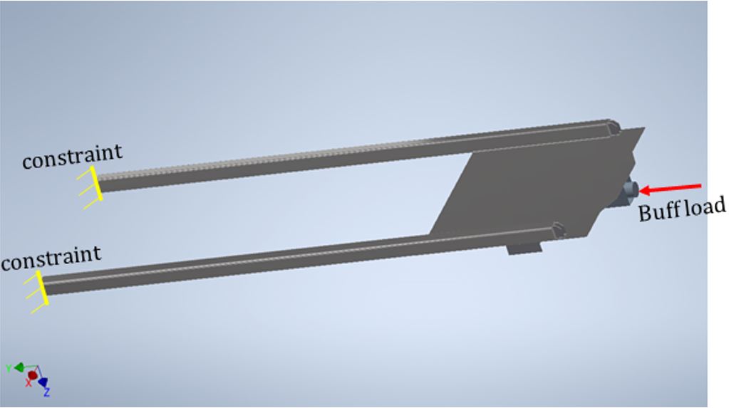
Modelling analysis was conducted using Autodesk Inventor Nastran software. Because the car tested at NRC failed in buckling of the shear plate, linear buckling analysis was selected to obtain the critical buckling load of the cars. For all of the analyses, a buff load of 1 000 000 pounds was applied. When buckling failure of a car model occurs, the analysis outputs an Eigenvalue (EIGV), which is a factor of the applied load. The critical buckling load of the car is determined by multiplying the output EIGV value and applied buff load, which is 1 000 000 pounds of force in this case. If the output EIGV value is less than 1, the critical buckling load of the car would be less than 1 000 000 pounds, meaning that the car would fail at an applied load of less than 1 000 000 pounds. If the output EIGV value is greater than 1, the critical buckling load of the car would be greater than 1 000 000 pounds, meaning that the car could fail at an applied load greater than 1 000 000 pounds.
First, a model for an intact platform structure of the car end without introducing any defect was analyzed. The result (Figure E2) shows that the output EIGV value (underlined in red) of an intact car is approximately 1.08. The critical buckling load of the intact car is thus calculated to be 1 080 000 pounds of force (i.e. critical buckling load = EIGV value ´ applied load =1.08 ´ 1 000 000 pounds of force = 1 080 000 pounds), indicating that the model of an intact car can take a buff load of 1 000 000 pounds of force without failure,Footnote 42 and failure could occur when the buff load reaches 1 080 000 pounds. The locations of buckles in the shear plate and their orientation are consistent with the result of compression testing at NRC.
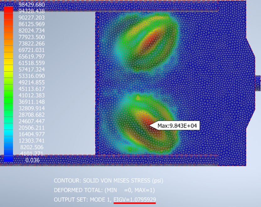
The model for the A-end of car DJJX 30156, which was of the same design as failed car DJJX 30478, was then built by introducing the observed defects into the intact model. Specifically, the thickness of the shear plate was reduced from 0.31 inches to 0.24 inches, and identified cracks in the shear plate and between the body bolster and shear plate were introduced into the model.
The results (Figure E3) show that the output EIGV value is approximately 0.63, indicating that the critical buckling load of the model of car DJJX 30156 was reduced to approximately 630 000 pounds of force (0.63 x 1 000 000), which closely matches the experimental result (628 000 pounds of force) obtained from the compression test with a relatively small deviation, indicating that the model is of reasonable fidelity.

A model for the B-end of the subject car DJJX 30478 was subsequently built using the same procedure by introducing identified defects into the intact model. The thickness of the shear plate was reduced from 0.31 inches to 0.19 inches, and an identified long crack in the shear plate at the location where it joins with the side sill was introduced. Analysis indicated that the output EIGV value was approximately 0.41 (Figure E4), indicating that the critical buckling load of the car was reduced to 410 000 pounds force (0.41 x 1 000 000) and the subject car DJJX 30478 B-end could fail when buff loads reached approximately 410 000 pounds of force.
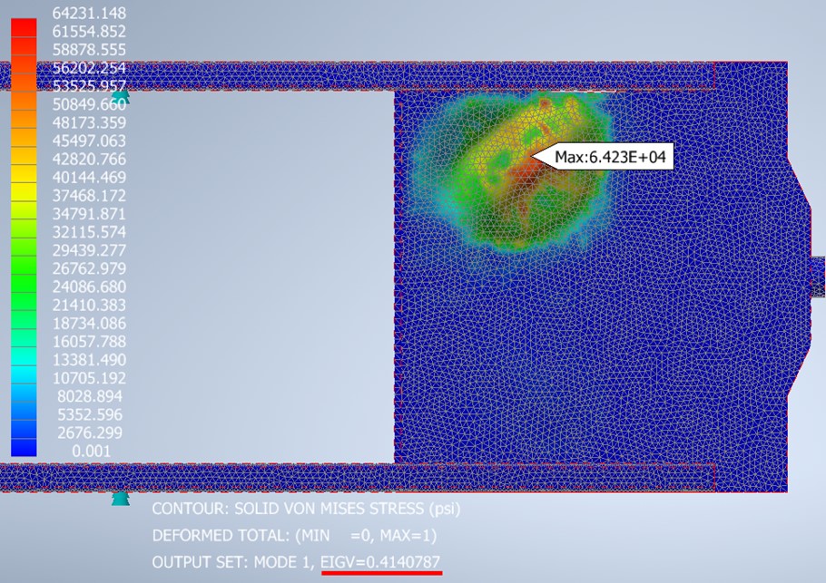
A model for the A-end platform structure of the subject car DJJX 30478 could not be built because complete measurement data for structural defects in the car end could not be obtained. A good portion of shear plate, one-quarter of the body bolster, and the left-side sill were not recovered.
FEM analysis of the B-end platform structure of the subject car DJJX 30478 calculated that the B-end would fail under a buff force of approximately 410 000 pounds of force (410 kips). Therefore, the A-end of the subject car, which failed in the tunnel, likely failed at a buff force below 410 kips.