Smoke in the cabin
Pascan Aviation Inc.
Beechcraft B100, C-FLKS
Montréal/Saint-Hubert Airport, Quebec
The Transportation Safety Board of Canada (TSB) investigated this occurrence for the purpose of advancing transportation safety. It is not the function of the Board to assign fault or determine civil or criminal liability. This report is not created for use in the context of legal, disciplinary or other proceedings. See Ownership and use of content. Masculine pronouns and position titles may be used to signify all genders to comply with the Canadian Transportation Accident Investigation and Safety Board Act (S.C. 1989, c. 3).
Summary
The Pascan Aviation Inc. Beechcraft B100 (registration C-FLKS, serial number BE123) operating as flight PSC123 departed the Montréal/Saint-Hubert Airport, Quebec, at 0907 Eastern Standard Time on a chartered flight to Bagotville, Quebec, with 2 passengers and 2 flight crew members on board. During the climb out, through 15 400 feet above sea level, the flight crew noticed very light smoke in the cabin. At 0928, the flight crew declared an emergency and requested a return to the Montréal/Saint-Hubert Airport. The aircraft touched down at 0951 on Runway 24R with emergency services in attendance. There were no injuries and there was no fire.
1.0 Factual information
1.1 History of the flight
On the day of the occurrence, the flight crew reported for work at around 0800Footnote 1 to prepare the aircraft for the first leg of a 3-leg flight. As the aircraft taxied for take-off, passengers advised the pilots that the temperature in the cabin was too cold. The electric heater (ELEC HEAT) switch was selected to the maximum heat ground position (GND MAX). A few minutes later, the cabin temperature increased to a comfortable level, and the electric heater was switched off before take-off.
At 0907, the aircraft took off from Runway 24R at the Montréal/Saint-Hubert Airport (CYHU) and turned right (northeast) towards Bagotville, Quebec. The pilot-in-command (PIC) was the pilot flying (PF), while the second-in-command (SIC) was the pilot not flying (PNF). During the climb, the cabin temperature became too warm, so the flight crew moved the cabin temperature control knob (CABIN TEMP-INCR) from the middle position toward the lower position. As the temperature in the cabin remained high, the flight crew then moved the cabin temperature mode (CABIN TEMP MODE) switch from the AUTO to the OFF position, and the blower switch was set to the high (HIGH) position to cool the cabin.
Approximately 27 nautical miles (nm) north of CYHU, the flight crew noticed very light smoke, which was barely visible in the sunlight. There was no perceptible odor.
At 0918, at an altitude of 15 400 feet above sea level (asl), the flight crew requested a clearance from air traffic control (ATC) to level off at 17 000 feet asl. The flight crew members started the emergency checklist for smoke/fumes in the cabin, but chose not to don their oxygen masks. The flight crew, believing that the smoke source was the bleed air system, momentarily interrupted the checklist to contact the company's maintenance department.
At 0920, the aircraft leveled at 17 000 feet asl, about 35 nm from CYHU and 35 nm from the Trois-Rivières Airport (CYRQ), Quebec. As the aircraft cabin was pressurized, the flight crew requested a descent. At 9000 feet asl, both bleed air valve switches were moved to the ENVIR OFFFootnote 2 position, and the smoke started to dissipate.
At 0928, the flight crew declared an emergency with ATC and requested to return to CYHU. At that time, the aircraft was 68 nm from CYHU and about 14 nm north of CYRQ. When the cabin's pressure altitude reached 8000 feet asl, the flight crew used the cabin dump switch to depressurize the aircraft, and the residual smoke cleared completely.
At 0933, the flight crew informed ATC that the No. 2 inverter was inoperative; 1 minute later, the SIC's microphone button became inoperative. Because of the electrical nature of the problem, ATC advised that, in case of a loss of communication, PSC123 was cleared to proceed for an approach to Runway 24R at CYHU. The flight crew completed the inverter failure checklist and selected inverter No. 1, which operated normally. Because the SIC could not use his microphone, the crew switched roles: the SIC assumed PF duties, and the PIC became the PNF.
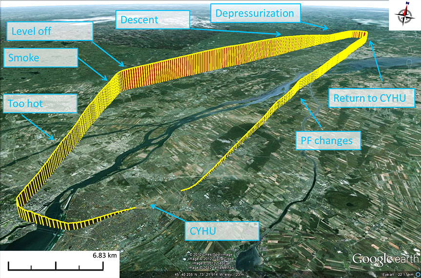
A visual approach was carried out, and the aircraft landed uneventfully at 0951, with CYHU aircraft rescue and fire-fighting (ARFF) services following the aircraft during the landing roll-out. Since there was no visible smoke, the flight crew taxied and parked the aircraft away from the company facility, escorted by ARFF. Figure 1 shows the aircraft's flight path.
1.2 Injuries to persons
| Crew | Passengers | Others | Total | |
|---|---|---|---|---|
| Fatal | 0 | 0 | – | 0 |
| Serious | 0 | 0 | – | 0 |
| Minor/none | 2 | 2 | – | 4 |
| Total | 2 | 2 | – | 4 |
1.3 Damage to aircraft
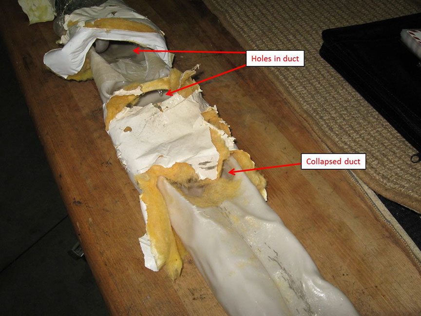
Three hot air duct sections carrying bleed air, located under the floor on the right side of the main cabin, were found melted, collapsed, and perforated (Photo 1). A de-icer pressure tube used for carrying air to the de-icing boots had also melted and collapsed. The No. 2 inverter, located under the right-side cabin floor, adjacent to the hot air ducts, had overheated, and its protection system had disconnected from the circuit during the event; there was no apparent damage.
1.4 Other damage
Not applicable
1.5 Personnel information
The flight crew was certified and qualified for the flight in accordance with existing regulations. The PIC had accumulated about 3100 total flight hours, with about 1200 hours as PIC on the Beechcraft B100. The PIC's last pilot proficiency check (PPC) on the B100 was completed in September 2011, and it was valid until 01 October 2012.
The SIC had accumulated about 1900 total flight hours, including 150 hours as SIC on the Beechcraft B100. The SIC's last PPC on the B100 was completed in December 2011, and it was valid until 01 January 2013.
1.6 Aircraft information
1.6.1 General
Records indicate that the aircraft was certified and equipped in accordance with existing regulations and approved procedures.
On 10 February 2012, 11 days before this occurrence, a discrepancy was noted in the occurrence aircraft log book, which indicated that the right-hand bleed air warning lightFootnote 3 had illuminated during take-off. After an investigation by the company's maintenance department, a bleed air line was found disconnected in the aft cabin on the right side. A disconnection leads to a drop in pressure inside the tube, which triggers the warning light. On 17 February 2012, a discrepancy was again noted in the log book, which indicated that the right-hand bleed failed when using de-icer boots. A bleed air line was found damaged; it was replaced, and the aircraft was returned to service. There was no entry in the log book indicating that other components adjacent to the bleed air line (such as hot air ducts) had been checked.
1.6.2 Protective breathing equipment
According to section 703.67 of the Canadian Aviation Regulations (CAR):
- No air operator shall operate a pressurized aircraft unless protective breathing equipmentFootnote 4 with a 15-minute supply of breathing gas at a pressure-altitude of 8,000 feet is readily available at each flight crew member position.
- The protective breathing equipment referred to in subsection (1) may be used to meet the crew member oxygen requirements specified in section 605.31Footnote 5
The operational requirements of CAR Parts VI and VII require PBE for 2 different roles:
- The use of fixed or portable PBE by flight crew members at their assigned duty stations on the flight deck (the PBE is easily accessible for immediate use).
- The use of portable PBE by all crew members when investigating and combating fires throughout the aircraft.
Technical standard orders (TSO) C78 and C89 masks are designed to meet the oxygen supply standard and have communication capability. TSO C99 PBE meets TSO C78 and C89 standards, and also includes smoke protection features. The mask can be combined with certified goggles (circulating fresh air) or come as a full-face device. It also has communication capability and is fixed.
TSO C116 PBE consists of a portable device (hood) and comes with its own oxygen generator. There is no communication capability, as the device is designed to be portable.
The occurrence aircraft (C-FLKS) is equipped with oral-nasal oxygen-type masks, which cover the mouth and nose only, and provide a continuous flow of oxygen. They are equipped with a re-breather bag that helps recycle parts of the exhaled air, thereby saving oxygen. They also comprise holes allowing ambient air to enter inside the screens. This type of mask adds oxygen to the cabin air entering through these holes, so the concentration of smoke or toxin breathed by the flight crew is reduced. These masks meet the type certificate of the aircraft; however, they do not meet the CAR requirements.
To meet the CAR 703.67(1) requirement and the CAR definition of PBE, the company installed smoke goggles in its Beechcraft aircraft as additional equipment. However, these smoke goggles are not combined with the existing masks, and do not provide circulating fresh air to the crew.
To meet the requirements of CAR 551.03, “the installation of the equipment must meet the applicable standards of the certification basis of the aircraft”Footnote 6. The actual Beechcraft illustrated parts catalog (IPC) doesn't list any PBE that meets the regulation in Canada. Consequently, operators are not allowed to install approved PBE in their aircraft. A supplemental type certificate (STC) that covers the installation of approved PBE would have to be developed, accepted, and available to Beechcraft owners, before the equipment could be legally installed in Canada.
A risk assessment conducted by Transport Canada (TC)Footnote 7 in 2011 stated that, despite the requirement for PBE, most CAR 703 operators do not have this equipment installed. The assessment determined that the level of risk of operating aircraft without PBE is medium to high. In response to this risk, TC concluded that a staff instruction or advisory circular was required, and that Section 703.67 of the CARs needed to be enforced. At the time of report writing, the staff instruction or advisory circular had not been issued by TC.
1.6.3 Environmental system
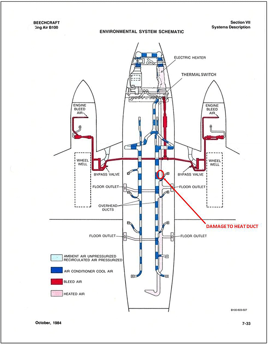
The required air for pressurization, cooling, heating, and surface de-icing is obtained by bleeding air from the compressor stage (P3) of each engine (Appendix B). The heat acquired from the bleed air may either be retained for cabin heating or dissipated for cooling purposes as the air passes through the centre section of the fuselage.
A flow control unit mounted on the forward side of the firewall in each engine nacelle regulates the mixture of the engine bleed air with ambient air from the cowling intake to produce a total air flow of 14 pounds per minute. The air from each flow control unit is routed through the firewall along the inboard side of each engine nacelle and inboard to the centre section, forward of the main spar.
The total hourly output of the bleed air heating system is 45 000 BTU.Footnote 8 During extremely low temperatures or low power settings, additional heating is available from an electrical heater containing 8 elements, rated at 1000 watts each. The maximum output of the electrical heater is 27 300 BTU during ground operation, with all heater elements operating. Once airborne, 4 elements are available, for a total output of 13 650 BTU.
A bypass valve, located adjacent to the heat exchanger, allows the hot air to be routed around the heat exchanger and into the cabin hot air ducts to heat the cabin in cold weather. The bleed air line from the tee is routed forward, along the right side of the fuselage, to a heat plenum just aft of the electric heater, under the floor of the nose compartment. A hot air duct from the aft side of the heater plenum extends aft under the right-hand seat deck of the cabin and distributes the heated air through the floor outlets on each side of the cabin (Appendix B).
The bleed air lines are not insulated and are located within 0.5 inches of the hot air duct, a few inches from the de-icer tube.
1.6.4 Environmental control panel of C-FLKS
An environmental control panel on the SIC's side of the cockpit is provided for automatic or manual control (Photo 2). It contains a vent blower switch (VENT BLOWER), an electrical heat switch (ELEC HEAT), a cabin temperature control knob (CABIN TEMP), a cabin temperature mode knob (CABIN TEMP MODE), 2 bleed air valve switches (BLEED AIR VALVE) and a manual temperature switch (MANUAL TEMP).
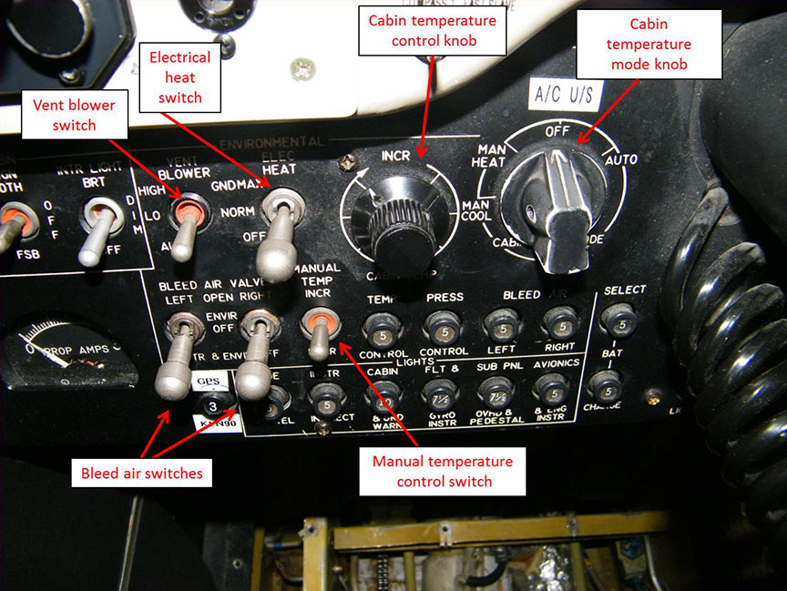
The 2 BLEED AIR VALVE switches (left and right) are placarded OPEN (top), ENVIR OFF (centre), and INSTR & ENVIR OFF (bottom). Each switch is a 3-position lever lock-type switch. It actuates an electric solenoid in the flow control units at the engines to bring warm, compressed air (bleed air) from the engines to the cabin.
The VENT BLOWER switch is placarded HIGH (top), LO (centre), and AUTO (bottom). The HIGH and LO positions allow for 2 speeds in manual operation. In the AUTO position, the blower will run continuously at low speed unless the electric heat has been set to the ON position, in which case the vent blower will automatically go to the HIGH position.
The ELEC HEAT selector switch has 3 positions: GND MAX (top), NORM (centre), and OFF (bottom). This switch is a solenoid held in the GND MAX position when the aircraft is on the ground. The switch will automatically drop down to the NORM position at take-off, when the landing gear safety switch is opened.Footnote 9 It provides maximum electric heat from all 8 elements of the electric heater for initial warm-up of the cabin. If the switch is placed in the NORM position for warm-up, only 4 elements will be utilized. In this position, the operation of the 4 elements is automatic in conjunction with the cabin thermostat to supplement bleed air heating. The OFF position turns off all electric heat, and the cabin is heated only with the bleed air system.
The CABIN TEMP control knob, placarded INCR on top with an indicator arrow, provides regulation of the temperature level when in automatic mode. A temperature sensing unit in the cabin, in conjunction with the control setting, initiates a heat or cool command to the temperature controller to achieve the desired cockpit and cabin environment.
A CABIN TEMP MODE knob is placarded MAN HEAT, MAN COOL, OFF, and AUTO. In the MAN HEAT or MAN COOL positions, regulation of the cabin temperature is accomplished manually with the MANUAL TEMP control switch. In AUTO mode, the temperature is selected with the cabin temperature knob. In the automatic mode, the motor-driven valves operate automatically, as regulated by the controller.
A spring-loaded MANUAL TEMP switch is placarded MANUAL TEMP INCR (top) and DECR (bottom). This switch controls the motor-driven bypass valves downstream of the heat exchangers in the wing centre sections. In manual mode, the valve opening is controlled manually by short touches on the switch to INCR or DECR, until the motor-driven valve reaches the position for the desired temperature.Footnote 10 Bleed air is bypassed around each heat exchanger.
1.6.5 Hawker Beechcraft caution message in maintenance manual
A caution message in section 21-40-00 of the Maintenance ManualFootnote 11 informs maintenance personnel that the bleed air lines must be installed a minimum of 0.5 inches from any electrical wiring aft of the heat exchanger, and that there must be at least 2 inches of space between non-insulated bleed air lines and all electrical wiring forward of the heat exchanger. This minimum distance may be reduced to 0.5 inches if the bleed air lines are wrapped with industrial oven insulation.
1.6.6 Pneumatic de-icer boots system
Pneumatic de-icer boots on the wings and on the horizontal and vertical empennage prevent the formation of ice during flight. Air pressure is used to inflate the boots, and the vacuum is used to deflate them. Regulated bleed air pressure and vacuum are cycled to the pneumatic boots for the inflation-deflation cycle. Ethylene-vinyl acetate (EVA) copolymer pressure tubes serve this purpose. They are routed under the right-side cabin floor, within inches from non-insulated bleed air lines and hot air ducts.
1.7 Meteorological information
Weather conditions for the planned route and destination allowed for flight in visual meteorological conditions. There is no indication that weather conditions were a factor in this incident.
1.8 Aids to navigation
Not applicable
1.9 Communications
Not applicable
1.10 Aerodrome information
Not applicable
1.11 Flight recorders
The aircraft was not equipped with a flight data recorder, nor was it required to be by regulations.
TC has indicated its intention to amend the CARs to require cockpit voice recorders (CVRs) to be carried on the Beech 100 and other similar aircraft. At the time of report writing, the CARs had not been amended.
In this event, the absence of a CVR meant that it was more difficult to establish the activities taking place and the communications between the pilots during the occurrence. Therefore, critical information was not available to assist investigators.
1.12 Wreckage and impact information
Not applicable
1.13 Medical and pathological information
Not applicable
1.14 Fire
Not applicable
1.15 Survival aspects
Not applicable
1.16 Tests and research
1.16.1 Hot air ducts examination and test
Several hot air ducts from the occurrence aircraft were sent to the TSB Laboratory for further examination to determine the cause of the damage. A new hot air duct (50-554244-71 rev. D) was also provided by the operator for comparison purposes. The manufacturer, Beechcraft, reported that the hot air ducts are made of a Lexan 90434Footnote 12 polycarbonate sheet, with a nominal thickness of 0.06 inches. The thickness of the undamaged portions of the subject hot air duct was measured, and the results met the manufacturer's thickness requirement.
An over-temperature test was conducted to provide an estimate of the conditions that would cause the thermal damage observed on the occurrence hot air ducts. Test results show that the Lexan 90434 polycarbonate material starts to deflect at around 145 °C (293 °F), and shows extensive deflection at 150 °C (302 °F). If no external load is applied, the material does not deflect at these temperatures, yet some distortion due to warping is observed. When the test temperature was increased to 185 °C (365 °F), the hot air duct bubbled, and at 200 °C (392 °F), the specimen turned white, similar to the condition observed on damaged portions of the occurrence hot air ducts. Comparable results were obtained using comparison hot air duct specimens.
The material specification for the grade of EVA used for the de-icing tube was not available. However, the melting point reported for EVA resin containing 18% vinyl acetate, which is the material that gives the best match, was 73 °C to 88 °C, depending on the grade.
1.16.2 Thermal switch and vent blower testing
The thermal switch (P/N 50-364531-5), also called the over-temperature switch, protects the electrical heating system. The thermal switch was recovered from the occurrence aircraft and was examined to determine its serviceability. The purpose of the thermal switch is to open the circuit to shut off the electrical heater any time the temperature in the plenum reaches 104 °C (220 °F). Once the thermal switch is triggered, the electric heater is disabled until the switch closes again. The test results showed that the occurrence thermal switch opened at 101 °C (214 °F), indicating that it was serviceable.
Testing of the vent blower differential pressure switch showed that it was not serviceable and would always remain in the normal closed state. A vent blower differential pressure switch in the normal closed state will enable the electrical heater to operate on all 8 elements. If all 8 elements work without air blowing through the heater, the temperature will rise until the thermal switch is triggered. If the thermal switch is serviceable, and the system functions in accordance with the control logic, the temperature should not exceed the thermal switch's trigger point of 104 °C (220 °F), even if the vent blower differential pressure switch is not serviceable, as determined when tested.
1.16.3 Ground tests on bleed air system
Tests were conducted on the occurrence aircraft's temperature control system to determine the temperatures that select components are exposed to under various operating conditions. The testing took place on 25 September 2012 at the operator's facility. Seats, carpet, and floor panels on the right side of the cabin were removed to obtain access to the related components (Photo 3).
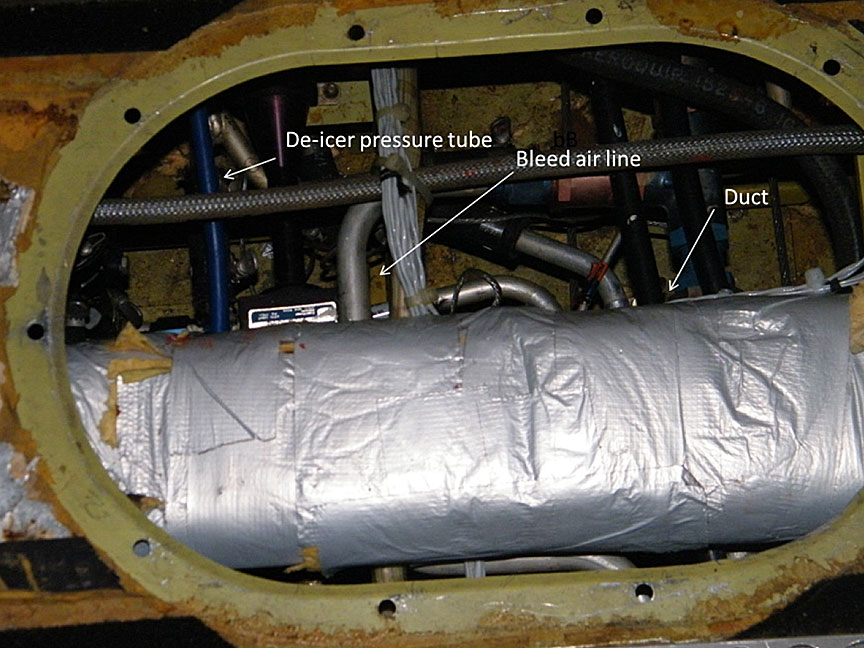
These tests were performed on the ground; therefore, the effects of the atmospheric pressure and external temperature changes to which these hot air ducts are exposed during high-level flight once the aircraft is pressurized, as well as the effects of engine load, could not be examined and consequently are unknown.
The following tests were performed:
- measurement of the bleed air temperature in the engine nacelle;
- measurement of the temperature in the hot air duct with the thermal switch removed;Footnote 13
- measurement of the temperature on the non-insulated bleed air line;
- measurement of the temperature in the hot air duct with the thermal switch in place.
When the engine was operating at full engine revolutions per minute (rpm), the maximum temperature recorded on the temperature probe, which was attached to a bleed air line in the left engine nacelle, was 116 °C. This temperature indication was affected by the ram air condition from the running propeller and engine.
The thermal switch was removed from the top of the heater plenum, at the juncture of the bleed air line, to replicate the maximum temperature obtained with an unprotected electrical heating system. With the engine operating at full engine rpm, a temperature of 148 °C was recorded by a probe attached to the non-insulated bleed air line in the cabin.
With the thermal switch in place, and the engine operating at full engine rpm, the maximum temperature recorded was 105 °C, suggesting that the thermal switch was functioning as intended. At this recorded temperature, damages caused by heat were almost impossible.
The operating conditions during the test may not be fully representative of the conditions present when the aircraft is at altitude, as was the case during this occurrence. Also, these tests were conducted with new hot air ducts, so it is not known what effect, if any, restrictions in the duct system would have if it were collapsed. The investigation was unable to establish with certainty how and when the hot air ducts were damaged.
1.17 Organizational and management information
1.17.1 General
Pascan Aviation Inc. holds a valid operating certificate to operate aircraft under Subparts 2 and 3 of Part VII of the CARs. This flight was operated under Subpart 3 of the CARs. At the time of the event, the company operated a fleet of 4 B100 aircraft, 11 British Aerospace Jetstream 31 aircraft, 2 Piper PA-31 Navajo aircraft, and 4 Pilatus PC-12 aircraft.
The company training program includes technical ground training, as well as initial and annual flight training. During these training sessions, many subjects are covered for pilots and air operations support staff, including normal, abnormal, and emergency procedures.
1.17.2 Emergency procedure for smoke or fumes in the cabin
The company's Beechcraft aircraft flight training is conducted on an aircraft, and not on a simulator; thus, it is not possible to simulate different conditions of smoke in the cabin. Therefore, pilots use their judgment based on past experience and training discussions to assess and interpret how best to respond to smoke or fumes in the cockpit or cabin. Furthermore, during training on the B100, the crew noted that oxygen masks are difficult to don, and once donned, are bulky and have holes which would permit cabin air to enter the mask.
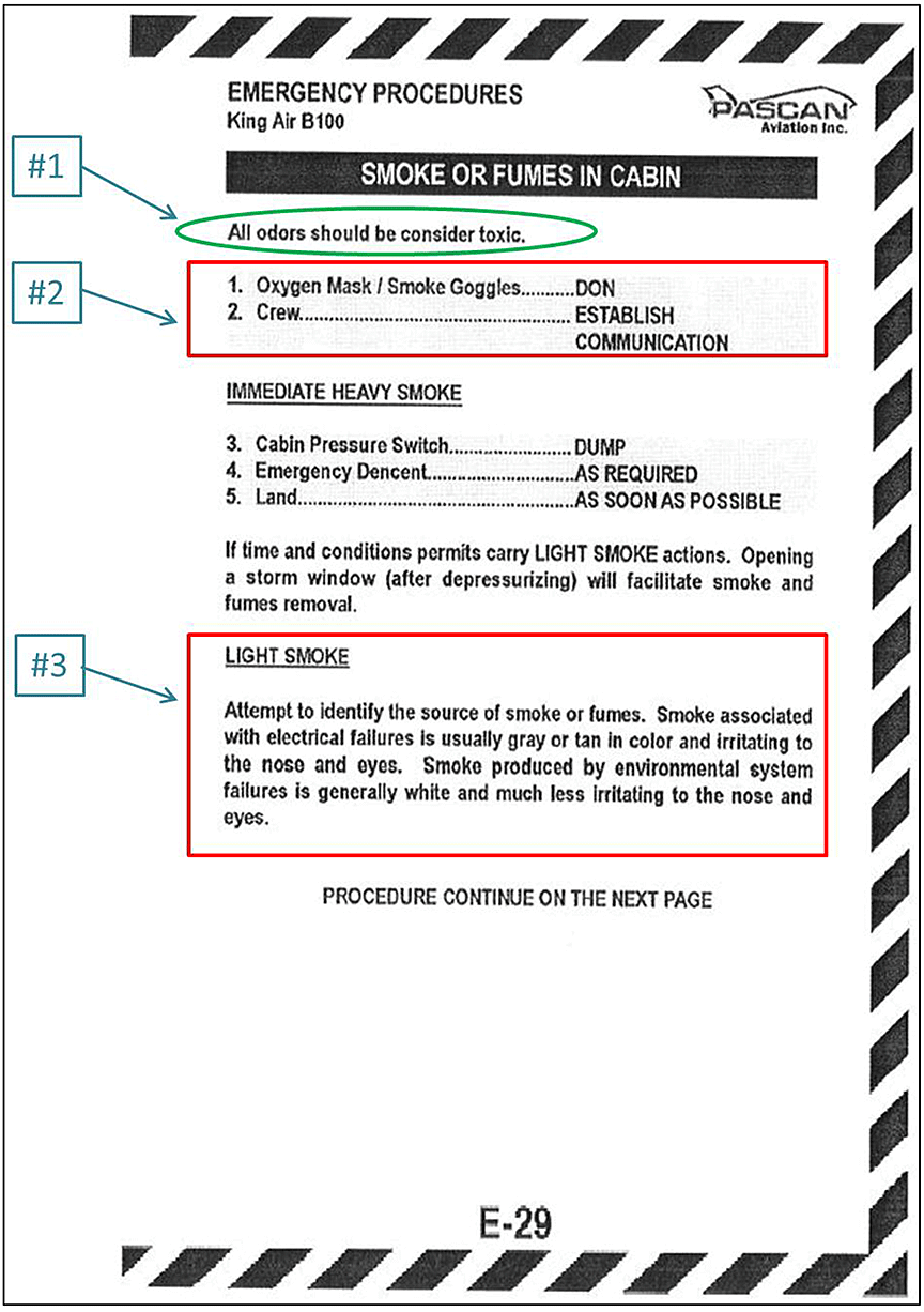
The SMOKE OR FUMES IN CABIN emergency procedure checklist (Appendix C) begins with a note advising that “all odors should be consider [sic] toxic” followed by the memory items:
- Oxygen Mask/Smoke Goggles DON
- Crew ESTABLISH COMMUNICATIONFootnote 14
The procedure then presents immediate actions to be performed in heavy smoke conditions. If light smoke is present in the cabin, the procedure provides guidance to establish the source of the smoke:
Attempt to identify the source of smoke or fumes. Smoke associated with electrical failures is usually gray or tan in color and irritating to the nose and eyes. Smoke produced by environmental system failures is generally white and much less irritating to the nose and eyes.Footnote 15
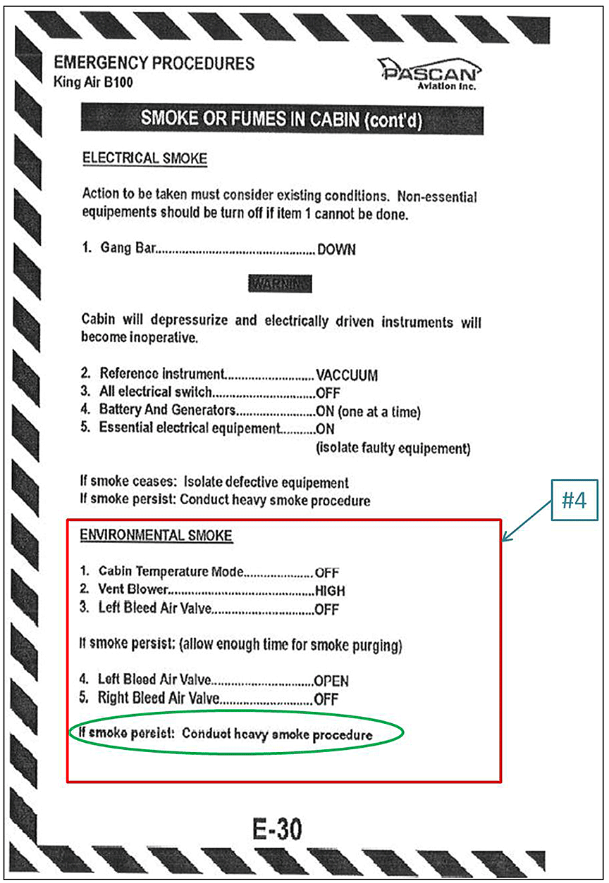
If the crew determines that environmental smoke conditions prevail, the following actions must be performed:
- Cabin Temperature Mode OFF
- Vent Blower HIGH
- Left Bleed Air Valve OFF
If smoke persist: [sic] (allow enough time for smoke purging)
- Left Bleed Air Valve OPEN
- Right Bleed Air Valve OFF
If smoke persist: [sic] Conduct heavy smoke procedureFootnote 16
The crew did not perform the first 2 memory items of this procedure, and therefore did not put on the oxygen masks or smoke goggles. The crew evaluated the smoke to be very light, and the procedure does not require to land as soon as possible. The crew then determined that the smoke was coming from the bleed air system, which is identified as environmental smoke according to this emergency procedure.
The flight crew completed the first 2 items of the environmental smoke section of the procedure; however, the crew did not close the left bleed air system. The procedure was interrupted to descend to 9000 feet asl, at which point the flight crew closed both bleed air systems simultaneously and the smoke dissipated.
1.17.3 Pascan Aviation Inc. maintenance inspection program
Pascan Aviation Inc. uses a 4-phase inspection program for its B100 series aircraft. Each phase is executed every 200 hours of flight. The phase inspection program must be completed within a 24-month calendar period. The operator imported the occurrence aircraft from the United States in the spring of 2011. At the time of importation, the company carried out a full phase inspection program from 1 to 4. The company could not provide inspection sheets for this investigation.
The program used by Pascan Aviation Inc. was amended by Beechcraft on 01 August 2011, under revision number A30. This revision covers Air Transport Association (ATA) chapter 26,Footnote 17 and includes section E (Pilot's compartment) and section F (Cabin section). Among the inspection phase requirements, phase 3 contains instructions to inspect insulatedFootnote 18 hot air ducts as follows:
- Inspect ducts for condition and security of installation.
- Check ducts for evidence of thermal leaks and/or degradation, such as discoloration of duct insulator, adjacent structure or components.
- Physically inspect ducts by touching ducts, checking for thermal deterioration, deformation of the ducts, and proper connection at the joints.Footnote 19
1.18 Additional information
1.18.1 Materials and workmanship certification
The Beechcraft B100 was certified by the United States Federal Aviation Administration (FAA) under the Federal Aviation Regulations (FAR) Part 23, amendment 23-3. Section 23.603 of the FAR provided that:
- The suitability and durability of materials used in the structure must be;
- Established by experience or tests; and
- Meet approved specifications that ensure their having the strength and other properties assumed in the design data; and
- Workmanship must be of a high standard.Footnote 20
1.19 Useful or effective investigation techniques
Not applicable
2.0 Analysis
2.1 General
The analysis section of the report will address the environmental system anomalies, resulting in smoke being detected in the aircraft cabin, as well as some aspects of the flight crew's response.
2.2 Environmental system anomalies
Based on the thermal damage observed, it is clear that the hot air ducts had been exposed to a range of temperatures from 185 °C to 200 °C, which is above the overheat protection system limits. However, the investigation could not pinpoint which environmental system component had failed, or when the deforming, melting, bubbling, and perforating of the hot air ducts took place. The heat escaping from the perforated hot air ducts likely caused the appearance of light smoke in the cockpit and cabin.
If the hot air ducts were damaged before the aircraft was imported in 2011, the damage should have been detected during the full phase inspection program. To properly check the air ducts, maintenance personnel must physically touch the ducts; otherwise, because the ducts are covered with insulation, it could be difficult to detect any thermal deterioration or deformation. However, the inspection sheets were not available to investigators. Considering that similar air duct damage was found on 3 other company B100 aircraft, it is reasonable to believe that inspections of the air ducts were not performed as per the maintenance inspection program.
The examination of the thermal switch that protects the electric heating system showed that it was operating normally. Additionally, when the thermal switch was removed so that the temperature limitation control system was not in place, the measured temperature inside the hot air duct was insufficient to cause deflection, even with the bleed air and electrical heating operating at the full hot position. Therefore, a past failure of the switch could not have been the cause of the thermal damage observed on the air ducts. The atmospheric pressure and the external temperature changes to which these hot air ducts are exposed during high-level flight (pressurized aircraft), as well as the effects of engine load, could not be examined and, consequently, are unknown.
The highest temperature measured on the non-insulated bleed air line during ground tests, with the thermal switch removed, was 148 °C. Bleed air lines run under the right cabin floor and are located very close to the hot air ducts, which start to deflect at 145 °C. Therefore, in some cases, the integrity of the hot air ducts may be affected by hot air, caused by the proximity of the ducts to the non-insulated bleed air line.
Considering that there were some environmental system issues with the aircraft at least 11 days before the occurrence, it is likely that one or a combination of the above-mentioned defective components could have started to affect the hot air ducts' integrity during this time. Also, in manual mode, the bypass valves can be driven fully closed, which can introduce bleed air hot enough to cause damage to air ducts. Therefore, if in the past, manual mode was used with the bypass valves fully closed, this could have introduced bleed air hot enough to cause the damage observed to the air ducts of the occurrence aircraft and 3 others.
All heating and bleed air components must be capable of resisting the highest operating temperatures encountered during any flight condition. The investigation determined that the Lexan 90434 polycarbonate material used by the manufacturer of the occurrence aircraft's hot air ducts did not resist the highest temperatures to which they may be exposed. Some Beechcraft airplanes examined during this investigation were manufactured entirely with phenolic hot air ducts, while others, like the 4 Beech B100 aircraft operated by Pascan Aviation Inc., used Lexan 90434 polycarbonate hot air ducts, which are more susceptible to damage caused by environmental heat exposure. As a result, the Lexan 90434 polycarbonate material used in this instance may not have been suitable.
The maximum melting-point temperature reported for the de-icer tube material was 88 °C. Because the de-icer tube was installed close to the non-insulated bleed air line and perforated hot air duct, the surrounding temperature was higher than the material could sustain. In this case, the de-icer tube collapsed completely, and rendered the empennage de-icing system inoperative. As the aircraft was not operating in icing conditions, the risk of not having de-icing capability was very low. Nonetheless, the same flight in icing conditions could have affected the safety of the flight.
2.3 Crew actions
When the flight crew noticed the presence of light smoke in the cabin, a request to stop the climb at 17 000 feet above sea level (asl) was made, and the applicable emergency checklist was initiated. Once leveled, the aircraft was at an equal distance of 35 nautical miles (nm) from the Montréal/Saint-Hubert Airport (CYHU) and the Trois-Rivières Airport (CYRQ). Given the low concentration of smoke and the non-perceptible odor, the flight crew members elected not to don their oxygen masks and goggles, despite the fact that it was called for in the SMOKE OR FUMES IN CABIN emergency procedure. The flight crew members made this decision based on their belief that this equipment would not provide much protection from the smoke, and therefore, would not be of benefit to the flight crew. If the available oxygen mask and goggles on the Beechcraft B100 do not provide adequate protection against smoke in the cockpit or cabin, there is increased risk of pilot incapacitation due to smoke inhalation. However, as these masks still add oxygen to the air breathed by the flight crews, the concentration of the smoke would be reduced. In addition, donning of the goggles reduces the risk of eye irritation. If protective breathing equipment (PBE) is not donned in the presence of smoke in the cabin, the risk of pilot incapacitation is increased.
According to Transport Canada's (TC's) risk assessment conducted in 2011, most Canadian Aviation Regulation (CAR) Subpart 703 operators do not have the required protective breathing equipment (PBE). At the time of report writing, there is no indication that TC has taken any action to enforce CAR 703.67. If PBE requirements are not enforced, there is an increased risk of fatality or injury to crews and passengers during smoke-related emergencies.
The crew correctly identified the bleed air system as the source of the smoke, but did not execute the published checklist items for light smoke. The crew did not try to identify which side of the bleed air system was affected by turning off the bleed air valve switches one at a time and allowing sufficient time for the smoke to purge. Instead, the flight crew turned off both bleed air valve switches, which eventually caused the smoke to dissipate. If checklist procedures are not followed during abnormal and emergency situations, flight crew and passengers may be at increased risk.
Declaring an emergency at the right time and clearly indicating the nature of the problem allows flight crews to get the best possible assistance during an abnormal or emergency situation. The emergency was declared 10 minutes after the appearance of the smoke. Although CYRQ was 14 nm away, the crew elected to return to CYHU, which was 68 nm away.
This decision was based largely on the fact that the smoke had dissipated, leading the pilots to believe that the source of the smoke had been isolated. The flight crew was also influenced by the fact that the checklist did not call for them to land as soon as possible in case of light smoke. Lastly, the flight crew also considered the fact that the company's maintenance base was located in CYHU. If flight is prolonged unnecessarily in an abnormal or emergency situation, the flight crew and passengers may be placed at increased risk due to possible unexpected and undesirable consequences associated with the event.
Although the smoke appeared to have dissipated, it was impossible for the flight crew to know the magnitude of the situation that had caused the smoke. While the decision to return to CYHU did not have any adverse consequences in this occurrence, this decision resulted in a longer risk exposure to a potentially more serious emergency.
3.0 Findings
3.1 Findings as to causes and contributing factors
- The heat generated by the non-insulated bleed air line affected the integrity of the air ducts and the de-icer tube due to their proximity.
- The hot air ducts were exposed to a temperature that caused thermal damage.
- The material used to manufacture the hot air ducts does not resist the highest temperatures to which they may be exposed under operating conditions; consequently this material may not have been suitable for this purpose.
- The air escaping from the perforated hot air ducts likely caused the appearance of light smoke in the cockpit and the cabin.
3.2 Findings as to risk
- If protective breathing equipment is not donned when smoke is present in the cabin, the risk of pilot incapacitation is increased.
- If checklist procedures are not followed during abnormal or emergency situations, the risk to the flight crew and passengers may be increased.
- If flight is prolonged unnecessarily in abnormal or emergency situations, it may place the flight crew and passengers at increased risk due to possible unexpected and undesirable consequences associated with the event.
- If the oxygen mask and goggles available on the Beechcraft B100 do not provide adequate protection against smoke in the cockpit or cabin, there is increased risk of pilot incapacitation due to smoke inhalation.
- If cockpit recordings are not available to an investigation, this may preclude the identification and communication of safety deficiencies to advance transportation safety.
- If protective breathing equipment requirements are not enforced, there is an increased risk of fatality or injury to crews and passengers during smoke-related emergencies.
3.3 Other findings
- The de-icer tube collapsed completely, rendering the empennage de-icing system inoperative.
- It is likely that the hot air duct inspections were not carried out in accordance with the maintenance inspection program.
- It was not possible to determine if the hot air duct damage occurred during this event or if it was due to repeated overheating of the system and/or environmental exposure to heat.
4.0 Safety action
4.1 Safety action taken
4.1.1 Pascan Aviation Inc.
Pascan Aviation Inc. reminded its maintenance personnel to closely inspect the hot air ducts and under-floor bleed air line installation. In addition, flight crews have been reminded to report any problems relating to the bleed air and heating system.
This report concludes the Transportation Safety Board's investigation into this occurrence. the Board authorized the release of this report on . It was officially released on .
Appendices
Appendix A – List of TSB Laboratory Reports
The following TSB Laboratory Report was completed, and is available from the TSB on request:
- LP033/2012 – Examination of Aircraft Air Ducts
Appendix B – Environmental system schematicFootnote 21
Appendix C – Emergency procedure – SMOKE OR FUMES IN CABINFootnote 22