Inadvertent descent during approach
Canadian Helicopters Offshore
Sikorsky S-92A (helicopter), C-GICB
Halifax, Nova Scotia, 155 NM ESE
The Transportation Safety Board of Canada (TSB) investigated this occurrence for the purpose of advancing transportation safety. It is not the function of the Board to assign fault or determine civil or criminal liability. This report is not created for use in the context of legal, disciplinary or other proceedings. See Ownership and use of content. Masculine pronouns and position titles may be used to signify all genders to comply with the Canadian Transportation Accident Investigation and Safety Board Act (S.C. 1989, c. 3).
Executive summary
On 24 July 2019, at 1154 Atlantic Daylight Time, a Canadian Helicopters Offshore (CHO) Sikorsky S-92A helicopter (registration C-GICB, serial number 920121), departed from Halifax/Stanfield International Airport, Nova Scotia, on an instrument flight rules flight to the Thebaud Central Facility, approximately 155 nautical miles to the east-southeast. On board were 2 pilots and 11 passengers.
Two instrument approaches were attempted at the platform but both were unsuccessful due to low clouds and poor visibility. During the second missed approach, the flight crew acquired visual contact with the platform and elected to carry out a visual approach. Shortly after they commenced the visual approach, a high-rate-of-descent and low-airspeed condition developed in low-visibility conditions. During the descent, the helicopter’s engines were overtorqued, reaching a maximum value of 146%. The crew regained control of the aircraft and arrested the descent at approximately 13 feet above the water.
During the subsequent hand-flown departure, a second inadvertent descent occurred but was rectified in a timely manner. The aircraft then returned to Halifax/Stanfield International Airport without further incident. The extent of the helicopter’s damage is unknown, as the helicopter has been removed from service. There were no injuries.
The investigation determined that during the final visual approach, the helicopter entered a low-energy state: it was flying at low airspeed with a high rate of descent, a nose-up pitch attitude, and at a low power setting. The helicopter’s low-energy state went undetected by the flight crew, who were focused on the helideck, which was sitting above the fog and in an area without a discernible horizon. The degraded visual environment (DVE) made it difficult for the pilots to recognize the unstable approach.
Contributing to the difficulties encountered, CHO standard operating procedures (SOPs) made no reference to energy state in its stabilized approach criteria, increasing the risk of a low-energy state developing and going undetected. Additionally, CHO had not adopted the recommended practice of requiring crews to check and verbally confirm that the approach was stable at specific intermediate progress targets (typically referred to as gates) on final approach. As a result, the SOPs provided flight crew with insufficient guidance to ensure that approaches were being conducted in accordance with industry-recommended stabilized approach guidelines.
The investigation also determined that while on final approach in a DVE, the pilot flying depressed and held the cyclic trim release. As seen in previous occurrences, this technique reduces the overall effectiveness of the automatic flight control system (AFCS). In this occurrence, the helicopter reached a nose-up attitude of 17°, an excessive rate of descent, and an increasing left sideslip while on final approach. Flying the visual approach in a DVE while depressing and holding the cyclic trim release button increased pilot workload and contributed to control difficulties that resulted in an unstable approach. As the helicopter descended below 250 feet radar altitude, it was in a steep, 800 fpm descent, at very low airspeed, with power being applied. When the pilot flying instinctively increased the collective, the helicopter’s rate of descent rapidly increased to 1800 fpm. The application of power while in a steep, low-airspeed, high-rate-of-descent condition caused the helicopter to enter vortex ring state.
Neither the manufacturer’s flight manual nor the operator’s SOPs warned of the potential hazards associated with the use of the trim release button under conditions such as a DVE. If manufacturers’ flight manuals and operators’ standard operating procedures do not include guidelines for the use of the cyclic trim release button, it could lead to aircraft control problems in a DVE due to the sub-optimal use of the AFCS.
The helicopter inadvertently descended with a very high rate of descent into the fog bank at low airspeed with the landing gear extended. Despite this, the helicopter’s enhanced ground proximity warning system (EGPWS) did not alert the crew to the situation. This is the result of a gap, previously identified by the TSB, in the coverage provided by the S-92’s EGPWS. If an inadvertent descent occurs with the gear down at airspeeds below 50 knots indicated airspeed, the EGPWS will provide no warning against controlled flight into terrain.
In 2016, the TSB issued a recommendation calling for terrain awareness and warning systems for commercial helicopters that operate at night or in instrument meteorological conditions. At the time of report writing, it is still not required by regulation. As a result, helicopter manufacturers and operators are free to disable EGPWS modes, as seen on the S-92A. Until EGPWS / helicopter terrain awareness and warning systems become mandatory for Canadian commercial helicopters that operate at night or in instrument meteorological conditions, flight crew and passengers aboard these flights are at increased risk of controlled flight into terrain.
1.0 Factual information
1.1 History of the flight
1.1.1 Departure
At approximately 0545Footnote 1 on 24 July 2019, the occurrence pilots arrived at the Canadian Helicopters Offshore (CHO) hangar at the Halifax/Stanfield International Airport (CYHZ), Nova Scotia. The pilots were scheduled to depart at 0700 for a passenger transport flight to and from the Thebaud Central Facility (TCF),Footnote 2 approximately 155 nautical miles (NM) east-southeast of CYHZ (Figure 1). The flight had originally been scheduled for 22 July, but was postponed due to low clouds and poor visibility at the TCF.Footnote 3 At approximately 0630 on the day of the occurrence, CHO dispatch advised the pilots and passengers that the flight was delayed until further notice due to low clouds and poor visibility at the TCF.
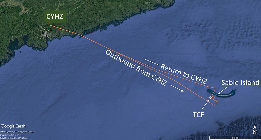
At approximately 1130, CHO dispatch notified the pilots that the offshore weather had improved enough to attempt the flight. At 1154, the helicopter departed CYHZ on an instrument rules flight (IFR) flight plan, with 2 pilots and 11 passengers on board. The helicopter flew toward the TCF at 7000 feet above sea level (ASL).
At approximately 1240, the weather observer on the TCF informed the pilots that the winds were approximately 300° true (T)Footnote 4 at 8 knots, the visibility was 1 statute mile (SM), and there was an overcast ceiling based at 300 feet above ground level (AGL); however, the cloud layer and visibility were fluctuating rapidly.
1.1.2 First 2 approaches to the Thebaud Central Facility
Once the aircraft was within 10 NM of the TCF, the pilots carried out the before landing check, conducted a 3-cue descentFootnote 5 to 800 feet ASL and positioned the helicopter for a Transport Canada (TC)–approved offshore/airborne radar approach (ARA) procedure,Footnote 6 with an into-wind inbound track of 320° magnetic (M). This procedure was followed because of the low clouds and poor visibility,
The crew attempted the approach procedure twice; however, neither attempt was successful because the crew did not acquire the visual references necessary to continue to a landing (Figure 2).Footnote 7 For these 2 approaches, the captain (occupying the right seat) was the pilot flying (PF) and the first officer (occupying the left seat) was the pilot monitoring (PM). The final approaches commenced at 5.6 NM and 6.7 NM from the TCF, respectively, level at 800 feet radar altitude (RADALT),Footnote 8 above a cloud layer, and at 100 knots indicated airspeed (KIAS).Footnote 9 On final approach, no drift correction was required to maintain the desired inbound track to the platform, and the airspeed and groundspeed were roughly the same. During both final approaches, the helicopter entered the clouds between 500 feet and 700 feet RADALT.
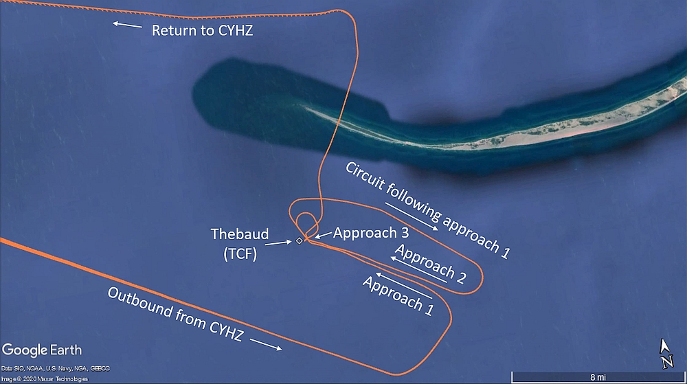
During both approaches, the pilots initiated a missed approach in accordance with CHO’s standard operating procedures (SOPs), because there were insufficient visual cues for landing, at approximately 0.5 NM from the TCF, at 225 feet RADALT and 55 KIAS. To avoid the platform’s superstructure, the missed approaches consisted of a climbing right-hand turn, approximately 30°, away from the TCF. The downwind leg of the circuit between the first and second offshore/ARA procedures was flown at 800 feet above the water, on top of the cloud layer, coupled with heading (southeasterly), airspeed, and RADALT hold,Footnote 10 roughly 2.0 NM northeast of the inbound approach track. The pilots had decided that they would proceed back to CYHZ if the second instrument approach was unsuccessful.
1.1.3 Third approach to the Thebaud Central Facility
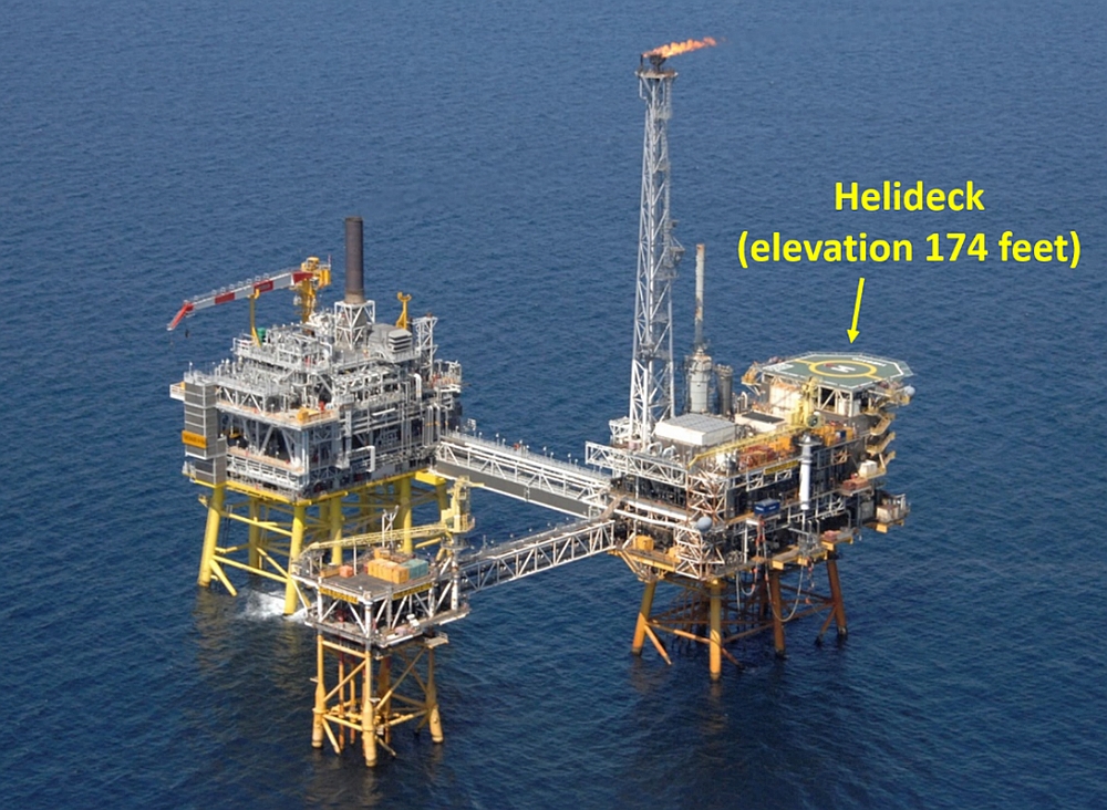
Approximately 15 seconds after initiating the second missed approach, at approximately 300 feet RADALT, the helicopter exited the cloud, horizontally. The PM informed the PF that the helideck, which is 174 feet above the water, was visible above the ragged layer of fog beneath them.Footnote 11 Although the TCF was in sight, there was no discernible horizon. As the helicopter climbed away, the PF looked across the cockpit and also observed the helideck above the fog layer.
The pilots determined that they had adequate fuel to attempt a third (visual) approach.Footnote 12 At that point, the pilots levelled off (engaged RADALT hold at 500 feet) and commenced a right-hand turn, using the heading hold autopilot mode, to assess the feasibility of conducting a visual approach. While the aircraft was in the turn, the airspeed, which was coupled to 80 KIAS in the climb to 500 feet RADALT, was reduced to 66 KIAS.
At 1332:15, approximately 1.1 NM from the TCF, the helicopter rolled out on a heading of 182°M and the crew planned their third approach. There was a ragged layer of fog below the helicopter and a scattered-to-broken layer of cloud at least several hundred feet above it. The pilots could see the water through the fog, directly beneath the helicopter. Since the winds were light (i.e., not registering on the primary flight displays [PFDs]Footnote 13), the pilots decided to, and briefed that they would, turn right to roll out on an inbound track of approximately 240°M, rather than continue arcing, as originally intended, until reaching the original inbound track of 320°M. Because the pilots planned to fly the final approach offset to the right of the TCF, this option was considered to be more expeditious and to provide better references for the first officer (who would fly the approach), since it would place the TCF off the left-hand side of the helicopter during the final stages of the approach to the helideck (Figure 3 shows approximate orientation before turning final). The pilots decided to remain at 500 feet RADALT.
Approximately 8 seconds after rolling out on a heading of 182°M, 1 NM from the TCF, the helicopter commenced a right turn to final. During the turn, the captain informed the first officer that he would be ready to transition to instrument flight in case the fog rolled in and the first officer lost visual references with the helideck.
At 1332:55, when the helicopter was 0.6 NM from TCF, it rolled out on final approach, on a heading of 271°M. The helicopter was level at 46% engine torque, coupled to RADALT at 500 feet and 61 KIAS. The airspeed and groundspeed were approximately the same.
The first officer stowed his approach plate, and prepared to take control. Because the first officer was seated in the left seat, he did not have visual contact with the TCF until the helicopter rolled out on final. When the helicopter rolled out, the captain transferred control to the first officer (who was now the PF). The helicopter was still flying above the fog layer, and both pilots had a clear line of sight to the helideck. The estimated flight visibility was approximately 3 SM in the direction of the TCF; however, there was no discernible horizon behind the TCF.
At 1333:02, when the helicopter was 0.5 NM from the TCF, the captain (who was now the PM) disengaged the airspeed mode, then the heading hold mode at the PF’s request.
At 1333:04, the PF depressed the cyclic autopilot disengage button to disengage the RADALT hold, then depressed and held the cyclic trim release button to hand-fly the approach. At the same time, the PF lowered the collective (decreased from approximately 45% engine torque to 27% engine torque), using the collective trim release trigger, to commence the descent. The descent commenced when the helicopter was 0.43 NM from the TCF, on a 7.1° approach angle to the helideck. The PM recognized that the approach was steeper than the company’s standard 4.7° approach angle; however, it did not alarm the PM because some company pilots preferred flying a steeper visual approach profile.Footnote 15 The PF asked the PM for the helicopter’s groundspeed, to which the PM replied it was approximately 60 knots.
At 1333:06, when the helicopter was 0.4 NM from the TCF, its rate of descent was 500 feet per minute (fpm) and increasing. To reduce the helicopter’s forward speed, the PF applied aft cyclic, causing the helicopter’s pitch attitude to increase to 12° nose-up. The PM informed the PF that the groundspeed was about 40 knots, which he considered to be slightly high given the light winds and the helicopter’s proximity to the TCF. The PF did not acknowledge this call. At the same time, left cyclic and right pedal inputs were being progressively applied, creating lateral drift to the left (i.e., south) of the intended track and right yaw, which kept the nose of the helicopter pointing in the direction of the helideck (so that the helicopter was side-slipping left).
At 1333:14, when the helicopter was within 0.3 NM of the TCF, at 415 feet RADALT, its pitch attitude increased to 15° nose-up. Two seconds later, the pitch attitude increased to almost 17° nose-up, and the helicopter briefly banked 6° to the right. During that time, the PF’s attention was focused outside, looking at the helideck. The PM, who had been primarily focused on the helideck, shifted his attention inside the helicopter and onto the flight instruments because he was losing sight of the helideck, (given that he was occupying the right-hand seat). The PM recognized the nose-up pitch attitude and, in accordance with company SOPs, called “15 degrees”. As this was happening, the airspeed decreased below 40 KIAS. The rate of descent was 670 fpm and increasing. Neither pilot was aware of the increasing rate of descent, the low engine torque setting of 27%, or the increasing left sideslip.
At 1333:20, the PF increased collective to 36% engine torque and the pitch attitude decreased to approximately 12° nose-up, even though the PF was applying increasing aft cyclic. Pedal input moved momentarily toward neutral, then increased to the right again. The PM continued to monitor the helicopter’s pitch attitude as it was reduced. The helicopter was at 350 feet RADALT, at low airspeed (i.e., less than 30 KIAS),Footnote 16 descending at approximately 850 fpm.
At 1333:26, at 250 feet RADALT with the helicopter at approximately 12° nose-up, all forward motion had been lost, and the rate of descent was 1200 fpm, and increasing. The sideslip angle reached approximately 40° nose right, with 18 knots lateral groundspeed. The PF recognized the helicopter was getting low and slowly increased collective to 45% engine torque, then rapidly increased to 103% engine torque, and applied cyclic opposite to the right bank (caused by sideslip), peaking at 22° right bank. As engine torque increased from 45% to 103%, at low airspeed, the rate of descent increased from 1200 to 1800 fpm as the helicopter descended below the helideck height; about 3 seconds after the engine torque reached 100%, the descent rate began decreasing (below 1500 fpm) (see Appendix A).
The PF did not verbalize that he had lost visual contact with the helideck. The PF shifted his attention to the flight instruments and observed the low airspeed and high rate of descent. The PM, who was initially unaware that the helicopter had descended into the fog and that the PF had lost visual contact with the helideck, observed the increasing rate of descent and informed the PF. At that point, the PM recognized that the helicopter was in the fog. The PM was just about to call for a go-around when the PF stated that he was commencing a go-around. During this time, the helicopter’s pitch attitude increased to almost 17° nose-up. The PM directed the PF to position the nose of the helicopter on the horizon, using the attitude indicator on the PFD.
1.1.4 Recovery from the inadvertent descent
As the helicopter descended below 100 feet RADALT, the PM, who could see the water directly beneath them, recognized the severity of the situation and placed his hands and feet on the flight controls and made control inputs to help the PF establish a wings-level attitude in anticipation of water impact.
At 1333:33, as the helicopter was passing through 70 feet RADALT, the collective lever was rapidly raised to the full up position and engine torque increased to 146%.Footnote 17 As the torque increased, the main rotor rpm (Nr) decreased rapidly (reaching a minimum of 77%), and the “LOW ROTOR” aural alert was triggered.Footnote 18,Footnote 19 The associated reduction in tail rotor thrust, as a result of the reduced Nr, proved insufficient to maintain directional control. As the helicopter reached 40 feet RADALT, it yawed uncontrollably to the right, despite full left yaw pedal being applied, for approximately 845° over a period of 55 seconds.Footnote 20 Due to the low Nr, the helicopter’s main generators dropped offline,Footnote 21 causing the automatic flight control system (AFCS) to revert to stability augmentation system (SAS) mode,Footnote 22 the helicopter’s attitude and heading reference system (AHRS) to drop offline,Footnote 23 and the helicopter’s centre and left-side (first officer) multi-function displays (MFDs) to display blank screens. As a result of these system failures, both pilots reverted to using the standby flight instruments.Footnote 24
At 1333:39, with the helicopter yawing to the right (greater than 60°/second), and Nr slowly increasing through 89%, the generators came back online and the pilots were able to arrest the descent within 13 feet or less of the water,Footnote 25,Footnote 26 in reduced visibility in fog. Water spray was visible on the helicopter’s windows. At its nearest point, the helicopter was less than 800 feet away from the closest part of the platform’s structure (1100 feet away from the TCF waypoint). As the helicopter descended, it drifted backwards, away from the TCF.
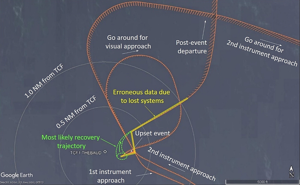
The captain, who could see the water and the TCF to the right of the helicopter, formally took control of the helicopter and began a near-vertical visual climb up to 150 feet RADALT, crosschecking with the standby instruments due to reduced visibility in fog. Some right yaw persisted during the climb and gradually reduced as the helicopter continued to climb. The aircraft flew in a widening right turn away from the vicinity of the upset and toward the northeast, accelerating from 30 KIAS to 80 KIAS (dashed zone shown in Figure 4; a detailed profile view is shown in Appendix B). A high-power setting (110–120% engine torque) was maintained during the initial climb and the Nr slowly increased, generally returning to 105% Nr at around 375 feet RADALT. As the helicopter climbed above 650 feet RADALT, engine torque was reduced to 100%, and continued steadily downward to approximately 70% as the helicopter reached 1350 feet RADALT.
At 1334:55, the helicopter’s altitude peaked at 1350 feet RADALT, then it began descending and the airspeed increased to 125 KIAS. While this was happening, the pilots attempted to engage barometric altitude hold twice; however, in both instances it failed with a master caution light. They also pressed the AFCS mode reset button on the AFCS control panel 8 times, without success.
Unbeknownst to the pilots, airspeed had increased to 148 KIAS, while descending through 650 feet RADALT at 1700 fpm. The PF recognized and arrested the descent at approximately 480 feet ASL (463 feet RADALT) as the helicopter was passing over the northwestern tip of Sable Island.Footnote 27 The captain then increased collective to regain the lost altitude. The pilots were unaware that the helicopter had overflown Sable Island. The helicopter was levelled off at 1500 feet ASL and the pilots assessed their options. Knowing that there were low clouds and visibility in the vicinity of the TCF and Sable Island, the pilots decided to return to CYHZ, where weather conditions would permit a visual flight rules (VFR) approach to landing.
Once the helicopter’s systems returned, several minutes later,Footnote 28 the pilots observed the “APU GCU FAIL”,Footnote 29 “DCU MISCOMPARE”,Footnote 30 and “LIMIT EXCEEDED”Footnote 31 caution lights illuminated on the engine indication and crew alerting system (EICAS) page of the multi-function flight displays. The pilots recognized the AFCS was degraded, which made the helicopter more difficult to fly accurately.
The pilots did not detect any other unusual controllability problems with the helicopter. The pilots believed that the cautions were related to the engine torque during the descent, so they elected to continue back to CYHZ without additional troubleshooting.
The captain coupled the helicopter’s autopilot to airspeed, heading, and altitude for the transit back to CYHZ. The flight crew elected not to declare an emergency. The helicopter landed back at CYHZ at 1439 without further incident.
1.2 Injuries to persons
There were no injuries to the 2 crew members or 11 passengers.
1.3 Damage to aircraft
1.3.1 General
The helicopter was removed from service. The full extent of the damage resulting from the occurrence is unknown.
1.3.2 Post-occurrence damage assessment
Following the occurrence, CHO inspected the airframe and engines in accordance with Sikorsky Aircraft Corporation (Sikorsky), and General Electric (airframe and engine manufacturer, respectively) instructions, and no faults were found. Neither CHO nor the TSB could complete electrical system troubleshooting due to the level of disassembly of the helicopter.
Additionally, Sikorsky gave CHO a list of components from the main and tail rotor assemblies and their associated drive systems that were required to be inspected and/or replaced in order to return the occurrence helicopter to service.
According to Sikorsky,
recorded HUMS [health and usage monitoring system] data suggests that the drivetrain sustained torque magnitudes in excess of the system design limits and therefore many component replacements are recommended. Due to the unusual conditions of the incident and recovery, the main rotor system loads are not fully understood at this time. It should be noted that removed components may be eligible for return to service upon detailed evaluation and further analysis.Footnote 32
The rotor and drive system components were sent to the manufacturer for further testing. However, shortly after the occurrence, CHO ceased operations at CYHZ. Because the helicopter was no longer required by CHO (which was leasing the helicopter), the owner of the helicopter elected not to conduct further inspections and the manufacturer did not complete an engineering analysis of the rotor and drive system components. As a result, the extent of the damage resulting from the over-torque was unknown at the time of report writing. Additional inspections would be needed before returning the aircraft to service.
1.4 Other damage
There was no other damage.
1.5 Personnel information
1.5.1 General
| Captain | First officer | |
|---|---|---|
| Pilot licence | Airline transport pilot licence - helicopter | Airline transport pilot licence – helicopter |
| Medical expiry date | 01 June 2020 | 01 July 2019 |
| Total flying hours | 6713 | 7742 |
| Flight hours on type | 2242 | 3196 |
| Flight hours in the 7 days before the occurrence | 8.9 | 5.8 |
| Flight hours in the 30 days before the occurrence | 20.4 | 21.5 |
| Flight hours in the 90 days before the occurrence | 114.3 | 131.3 |
| Flight hours on type in the 90 days before the occurrence | 114.3 | 131.5 |
| Hours on duty before the occurrence | 7 | 7 |
| Hours off duty before the work period | 18 | 16 |
1.5.2 Captain
The captain held a valid Canadian airline transport pilot licence – helicopter, with type ratings on the Sikorsky S-92A and S-61. His licence was endorsed with a Group 4 instrument rating.
The captain was an experienced offshore pilot, having flown for more than 20 years as an S-61 pilot in the Royal Canadian Air Force (RCAF), and more than 5 years as a civilian S-92A captain. From 2014 to 2017, the captain worked as an S-92A captain for a different civilian offshore helicopter operator, based out of Newfoundland. In 2017, the captain joined CHO as an S-92A captain and helicopter flight data monitoring (HFDM) representative.
The captain had accumulated more than 1100 flight hours in instrument meteorological conditions (IMC).
The captain’s training file revealed that he had completed
- initial and recurrent crew resource management (CRM) training in December 2017 and March 2019, respectively,Footnote 33 and
- recurrent simulator training, which included pilot incapacitation, on 09 March 2019.
There was nothing to indicate that the captain’s performance was degraded by fatigue or any other pre-existing physiological factors. In addition, there is no indication that the captain was feeling undue pressure to complete the flight.
1.5.3 First officer
The first officer, who was also an S-92A captain at CHO, held a Canadian airline transport pilot licence – helicopter, with type ratings on the Sikorsky S-92A, S-61, S-76, and Bell 206. His licence was endorsed with a Group 4 instrument rating.
The first officer’s Category 1 medical certificate had expired on 01 July 2019, almost 1 month before the occurrence. The first officer, who had turned 60 a few months before his most recent pilot medical exam on 03 December 2018, was not aware that the validity period of his medical certificate had changed to 6 months per paragraph 404.04 (6.2)(b) of the Canadian Aviation Regulations (CAR).
CHO’s computer-based personnel qualification tracking system mistakenly identified the first officer as being under 60 years of age. As a result, management personnel at CHO were unaware that the first officer’s pilot medical certificate had expired.
Like the captain, the first officer was an experienced offshore pilot, with extensive experience flying the S-61 in the RCAF and the S-92A in the civilian offshore environment. From 2008 to 2017, the first officer flew as an S-92A captain for another offshore operator, based out of Newfoundland. In 2017, the first officer joined CHO as an S-92A captain.
The first officer had accumulated more than 1300 flight hours in IMC.
The first officer’s training file revealed that he had completed
- initial and recurrent CRM training in June 2018 and November 2018, respectively, and
- recurrent simulator training, which included pilot incapacitation, on 24 November 2018.
There was nothing to indicate that the first officer’s performance was degraded by fatigue or any other pre-existing physiological factors. In addition, there is no indication that the first officer was feeling undue pressure to complete the flight.
1.5.4 Crew considerations
The occurrence pilots, who were both highly experienced captains, had known each other for several years and flew together periodically. Both pilots had a considerable amount of confidence and respect in each other’s abilities as a pilot. The investigation determined that there was a strong sense of team and alignment of mental models throughout most of the occurrence flight. The pilots interacted and coordinated activities with considerable ease and efficiency. At no time did either pilot feel that he was being put in an uncomfortable situation. There were no indications of issues related to trans-cockpit authority gradient.Footnote 34
Both the captain and the first officer had been on many previous flights where they were unable to land at an offshore facility because of the weather conditions at the time. These types of flights, referred to by pilots and passengers as “boomerangs,” are fairly routine for offshore helicopter operations off the East Coast of Canada. The pilots had also previously conducted visual approaches to a helideck that was above a layer of fog.
1.6 Aircraft information
1.6.1 General
| Manufacturer | Sikorsky Aircraft Corporation |
|---|---|
| Type, model and registration | S-92A, C-GICB |
| Year of manufacture | 2009 |
| Serial number | 920121 |
| Certificate of airworthiness issue date | 07 April 2018 |
| Total airframe time | 5652.9 hours |
| Engine type (number of engines) | General Electric CT7-8A (2) |
| Rotor type (number of blades) | Fully articulated (4) |
| Maximum allowable takeoff weight | 26 500 pounds |
| Recommended fuel types | JP-4, JP-5, JP-8, JET A, JET A-1, JET B, No. 3 Jet Fuel |
| Fuel type used | Jet A-1 |
The S-92A is a four-bladed twin-engine medium-lift helicopter built by Sikorsky (Figure 5). The occurrence helicopter was configured to carry 2 crew members, 1 internal auxiliary fuel tank, and up to 16 passengers in the cabin. Records indicate that the helicopter was certified and equipped in accordance with existing regulations and was within its weight and centre-of-gravity limits. There was no indication of an aircraft system malfunction before the inadvertent descent.

1.6.2 S-92A Flight instrument panel
The CHO S-92A instrument panel consists of 5 Collins Aerospace MFDs (Figure 6). On the occurrence flight, MFDs 1 and 4 were set to the primary flight display page, MFDs 2 and 3 were set to the EICAS page, and multi-function display 5 was set to the Navigation page. This was CHO’s standard configuration for offshore flight operations.
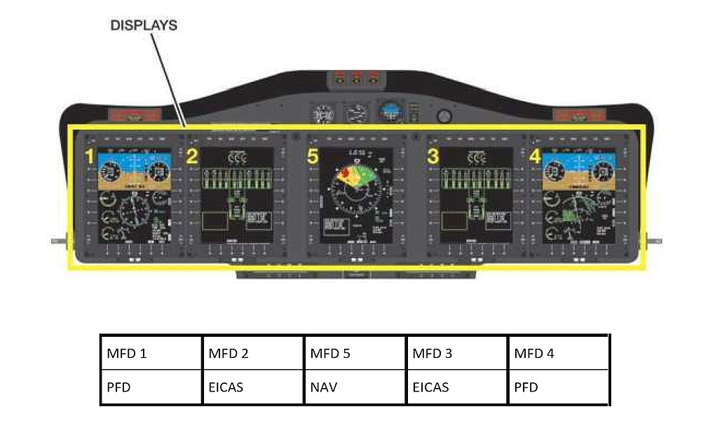
In the event of a MFD failure, pilots must revert to the standby flight instruments located above MFD 5 (Figure 7).
![Location of standby instruments (Source: Sikorsky, <em>FAA Approved Rotorcraft Flight Manual: Sikorsky Model S-92A, </em>SA S92A-RFM-003, Revision 8 [02 May 2012], Part 2, Section I, Chapter 4: Avionics Management System, p. I-4-31)](./images/a19a0055-figure-X07X.jpg)
1.6.3 Electrical power
1.6.3.1 General
Two main generators and a backup auxiliary power unit (APU) supply alternating current (AC) electrical power. The S-92A is also equipped with 2 AC-powered direct current (DC) converters, an AC-powered backup converter, and a 15 ampere‑hour nickel-cadmium battery that provides DC power.Footnote 35
1.6.3.2 Main generators
The main generators produce 115 volts alternating current, 75 kilo-volt-amperes alternating current , as the primary source of power for the helicopter. The generators are driven by the main transmission accessory modules, above 96% Nr on the ground and 80% in the air.Footnote 36 If Nr decreases below 80%, while in flight, the main generators will drop offline and the associated AC GEN 1 FAIL and AC GEN 2 FAIL cautions will appear on the EICAS.
If both main generators fail or drop offline in flight, and backup AC power (from the APU) is not available, only systems powered by the battery busesFootnote 37 will be available. As a result, the following system degradations, relevant to this occurrence, will occur:
- autopilots will be lost
- flight controls revert to SAS mode
- AHRS will be lost
- trim system (cyclic, collective, and yaw) will be inoperative
- centre and co-pilot multi-function displays (MFDs 1, 2, and 5) will go blank
- active vibration control (AVC) reverts to degradedFootnote 38,Footnote 39
- automatic float deployment will be inoperativeFootnote 40,Footnote 41
1.6.3.3 Auxiliary power unit
The S-92A is equipped with an air-cooled brushless APU-driven auxiliary generator that produces 115 VAC. The APU generator, which is authorized for use in flight, provides ground and emergency AC power when both generators are offline. The APU burns approximately 57 pounds of fuel per hour.Footnote 42
If the APU is running, and both main generators fail or drop offline, the APU generator will supply reduced power to the AC buses. The APU is not capable of supporting all AC loads, so automatic load shedding will occur and the following will be disabled:
- Pilot and co-pilot windshield anti-ice
- Number 1 engine anti-ice
- Main and tail rotor blade de-ice
- AVC System
- Second air conditioning compressor (if installed)Footnote 43
The CHO SOPs stated that, in order to have a backup source of AC power, the APU was to be started during an emergency descent or evacuation at sea or over the land and before carrying out search and rescue operations in IMC or low visibility.Footnote 44,Footnote 45
At the time of the occurrence, the helicopter’s APU was not running, and there was no requirement in CHO’s SOPs to have it running during an offshore approach. The investigation determined that some S-92A operators start the APU as a precautionary measure before commencing certain offshore operations. Some other S-92A operators tried, but subsequently abandoned, this procedure due to increased maintenance resulting from additional APU cycles.
In this occurrence, the “APU GCU FAIL” caution light illuminated following the inadvertent descent. As a result, the pilots were unable to start the APU when they were back at CYHZ, per the normal shutdown procedure. According to the manufacturer, the illumination of the “APU GCU FAIL” caution light in this occurrence may be related to the system’s continual built-in-test; however, a precise trigger for this failure was not determined. As a result of this failure, the APU would not have been available in flight if emergency AC power had been required on the return to CYHZ.
1.6.4 Enhanced ground proximity warning systems
1.6.4.1 General
Although not required by regulation, the occurrence helicopter was equipped with an enhanced ground proximity warning system (EGPWS).Footnote 46,Footnote 47 The model installed on the occurrence helicopter, the Honeywell Mk XXII, was first introduced in 2001. The system consists of basic modes based on RADALT, and forward-looking modes (inhibited below 70 KIAS) based on global positioning system (GPS) position compared to terrain and obstacle databases.Footnote 48 The various EGPWS modes are described in the S-92A rotorcraft flight manual (RFM).
1.6.4.2 Mode 1
Mode 1 is intended “to detect when the aircraft is descending toward terrain at a high rate for its relative altitude above terrain.”Footnote 49 Mode 1 is inhibited on the S-92A. According to Sikorsky, Mode 1 was prone to nuisance alerts on the S-92A during initial certification testing in 2002. Sikorsky believed these nuisance alerts would unduly degrade a pilot’s confidence in the system. Consequently, Sikorsky asked Honeywell not to include Mode 1 in the S-92A configuration of the Mk XXII EGPWS. The Mode 1 envelope was subsequently updatedFootnote 50 in 2003 to address previous concerns about nuisance alerts; however, Mode 1 remained inhibited on the S-92A. Following simulator evaluations in March 2018, Sikorsky decided to begin the process to enable Mode 1.
In March 2020, Honeywell issued a service bulletin for the field update of the Mk XXII EGPWS to software version EGPWS-036.Footnote 51 This version of the software incorporates recommendations made by the UK Civil Aviation Authority including an enhanced Mode 1 envelope (i.e., earlier detection).Footnote 52 Sikorsky plans on incorporating EGPWS-036, with Mode 1 enabled, when it installs version 11 of the avionics management system (AMS), anticipated for U.S. and worldwide release in late 2021 and early 2022, respectively. The manufacturer did not specify how long it would take for AMS version 11 to be installed across the S-92A fleet.
The investigation determined that the Mk XXII is installed in many different helicopter types; however, the S-92A is the only Mk XXII-equipped helicopter with Mode 1 inhibited.
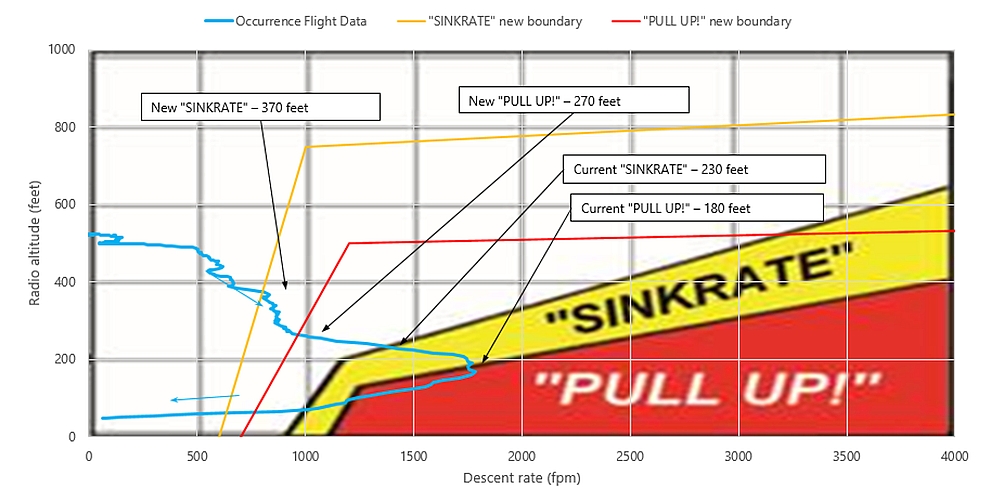
The occurrence helicopter entered the Mode 1 “SINKRATE” alert envelope as it descended through 230 feet RADALT and the “PULL UP!” alert envelope as it descended below 180 feet RADALT. The new EGPWS-036 Mode 1 envelope would have resulted in significantly earlier “SINKRATE” alerts (370 feet RADALT) and “PULL UP!” alerts (270 feet RADALT). The applicable alerts with the EGPWS-036 would have been issued approximately 9 and 4 seconds before their respective existing Mode 1 alerts. However, because Mode 1 was inhibited, the pilots did not receive any aural or visual warnings.
Figure 8 shows a comparison of the occurrence flight profile compared to the current and new (EGPWS-036) Mode 1 alert envelopes.
1.6.4.3 Mode 2
Mode 2 of the EGPWS provides alerts when the aircraft is closing with terrain at an aggressive rate. The system filters radar altitude data from the aircraft to produce a terrain closure rate, and generates alerts when the terrain closure rate is high relative to the aircraft’s height above terrain.
1.6.4.4 Mode 3
Mode 3 provides alerts when the aircraft loses a significant amount of altitude immediately after takeoff. According to the S-92A RFM,Footnote 53 Mode 3 is active after takeoff, when the landing gear is raised or when the airspeed is greater than 50 KIAS, and remains enabled until the helicopter has gained sufficient altitude so that other modes will protect against controlled flight into terrain (CFIT) (normally 60 seconds after takeoff). However, to allow for the repositioning of the helicopter in the airport environment or for a rejected takeoff, Mode 3 is inhibited when the airspeed decreases to below 50 KIAS and the landing gear is down. According to the manufacturer, this is to prevent the “DON’T SINK” Mode 3 aural alert during an air taxi (liftoff, manoeuvre, and touchdown). The manufacturer also determined that a normal takeoff will attain greater than 50 KIAS. Therefore, if the helicopter descends and slows down below 50 KIAS, the system logic assumes that the pilot is intending to land. This mode does not take rate of descent into account.
1.6.4.5 Mode 4
Mode 4 is designed to alert the pilot when the helicopter descends below a predetermined terrain clearance value or floor. This mode has 3 sub-modes, depending on the helicopter’s airspeed and landing gear configuration.
Mode 4A is active in cruise and during approach when the gear is up. A “TOO LOW, TERRAIN” aural alert is given and a yellow TERRAIN caution light on the attitude director indicator (ADI) illuminates when the airspeed is above 60 KIAS and the RADALT is below 150 feet. A “TOO LOW, GEAR” aural alert is given, a yellow GEAR caution light illuminates on the ADI, and LDG GEAR illuminates on the master warning panels when the airspeed is at or below 60 KIAS and RADALT is below 150 feet.
Mode 4B is active during cruise and approach when the gear is down. In this case, a “TOO LOW, TERRAIN” aural alert is given when the RADALT is below 100 feet and the airspeed is above 120 KIAS. As the airspeed decreases, the alert boundary decreases to 10 feet and 80 KIAS.
Mode 4C is active during the take-off phase, when the airspeed is greater than 50 KIAS and the landing gear is up. This mode ensures that the aircraft is moving further away from the ground after takeoff and is based on a floor of 75% of the current radar altitude. A “TERRAIN” aural alert is given when terrain clearance is less than the changing altitude floor. In this mode, as the airspeed decreases, the alert boundary decreases to 10 feet and 80 KIAS.
1.6.4.6 Mode 5
Mode 5 is a glideslope alert, designed to alert pilots that the helicopter has descended below the glideslope on an instrument landing system (ILS) approach.
1.6.4.7 Mode 6
Mode 6 provides alerts for excessive bank angle (based on RADALT, roll attitude, and roll rate) and tail strike warning (based on RADALT, pitch attitude, pitch rate and descent rate). Altitude advisories are also provided.
1.6.4.8 Mode 7
Mode 7, which the occurrence helicopter’s EGPWS was not equipped with, “provides protection against loss of airspeed on approach using input parameters of IAS [indicated airspeed] and Total Torque.”Footnote 54 This mode is part of Honeywell’s EGPWS-036 software update; however, Mode 7 will not be certified on the S-92A with EGPWS-036 due to concerns about the use of a “CHECK AIRSPEED” aural alert versus a “POWER POWER” aural alert.
A comparison of the occurrence flight data with the Mode 7 alert boundary shows that a “CHECK AIRSPEED” alert would have occurred as the airspeed dropped through 45 KIAS. At that point, the helicopter was descending through 420 feet RADALT. This alert is about 13 seconds earlier than the current Mode 1 alert, and 4 seconds earlier than the new Mode 1 alert. Therefore, given the particular flight parameters of this occurrence, the new Mode 7 would have been the first alert. Prompt corrective action following a Mode 7 alert could possibly prevent a Mode 1 alert situation. The specific Mode 7 envelope for the S-92A, with occurrence data overlaid, is shown in Appendix C.
1.6.4.9 Alerts during the occurrence
Due to the configuration of the helicopter (landing gear down) and the airspeed at the time of the inadvertent descent (below 40 KIAS), none of the EGPWS mode alerts described above activated.
1.6.4.10 TSB Recommendation A16-10
In this occurrence, the helicopter was equipped with an EGPWS, although it is not required by regulation. Since there is currently no requirement for commercial helicopters to be equipped with an EGPWS, nothing prevents a manufacturer and/or operator from inhibiting modes of an installed EGPWS, which in turn degrades the system’s capabilities. In this occurrence, the overall capability of the system was degraded due to Mode 1 being inhibited. This prevented the pilots from receiving Mode 1 EGPWS alerts and warnings during the occurrence.
Following a 2013 CFIT accident involving a Sikorsky S-76 helicopter conducting a nighttime departure from Moosonee Airport, Ontario,Footnote 55 that was not equipped with a terrain awareness warning system, the TSB recommended that
the Department of Transport require terrain awareness and warning systems for commercial helicopters that operate at night or in instrument meteorological conditions.
Recommendation A16-10
In December 2020, in its most recent response, TC indicated that it agrees in principle with the recommendation. TC highlighted that:
- The topic of helicopter terrain awareness and warning systems (HTAWS) is still under discussion within the TC Night VFR Working Group. To date, no recommendations have emerged from this working group.
- TC plans to address the safety considerations for helicopter operators who conduct only VFR operations (day or night) separately from those who also conduct IFR operations.
- For VFR-only helicopter operations, TC will continue to encourage the use of HTAWS and other capabilities, while continuing its efforts to amend Canadian Aviation Regulations (CARs) 602.114 and 602.115 to redefine visual references for flight at night.
For IFR helicopter operations, TC will assess the safety deficiency, keeping in mind the International Civil Aviation Organization’s recent recommendation to shape regulations in a capability-based manner.In February 2021, in its reassessment of TC’s latest response, the TSB noted that, as there is no clear indication as to what actions will be taken, and when those actions will be completed, it is unclear how and if the ensuing actions will address the intent of this recommendation.
Therefore, the Board remains unable to assess TC’s response to Recommendation A16-10.Footnote 56
1.6.5 Automatic flight control system
1.6.5.1 General
The occurrence helicopter was equipped with an AFCS that stabilizes the helicopter in the yaw, roll, and pitch axis to allow for trimmed hands-off flight in most steady-state flight conditions. It does this through a trim system, SAS, attitude hold (ATT) features, and a coupled flight director (CFD).
The cyclic control incorporates an electromagnetic brake and spring. This allows the pilot to set an attitude that will be used by the cyclic trim system as its reference for pitch and roll retention. This is referred to as being in detent. A similar type of trim system is used on the collective to hold a reference position, an altitude, or a rate of climb, as selected by the pilot. Yaw is trimmed to a pedal position, a heading reference, or a lateral sideslip reference as directed by the pilot or the autopilot.
Four electromechanical trim actuators provide control referencing and artificial control gradient. Each actuator has a clutch system that allows the pilot to override trim actuator input if desired. These actuators are responsible for attitude retention and CFD operations.Footnote 57 The CFD will not couple to the pitch or roll axis unless the airspeed is above 50 KIAS (VMINI).Footnote 58 The RADALT hold can be engaged at any airspeed.Footnote 59
1.6.5.2 Trim release
Inputs from the trim actuators can be disengaged by depressing the trim release button located on the cyclic (solid circle, Figure 9), the trim release trigger on the collective (solid circle, Figure 10), or the tail rotor pedals. The actuators can also be controlled by the 4-way trim beeper switches located on the cyclic and collective (dashed circles, Figure 9 and Figure 10).
![S-92A cyclic stick, trim release (solid circle); trim beeper switch (dashed circle) (Source: Sikorsky, <em>FAA Approved Rotorcraft Flight Manual: Sikorsky Model S-92A</em>, SA S92A-RFM-003, Revision 8 [02 May 2012], Part 2, Section I, with TSB annotations)](/sites/default/files/eng/rapports-reports/aviation/2019/a19a0055/images/a19a0055-figure-09.jpg)
In ATT mode,Footnote 60 pressing and releasing the cyclic trim release button will re-reference the cyclic trim force to the new stick position and corresponding pitch and roll attitude. If the pilot applies a cyclic input without first depressing the trim release, it will “result in an increasing force towards the reference.”Footnote 61
Attitude changes can also be made using the AFCS trim beeper switch. Lateral AFCS trim beeper input will move the cyclic left or right at a roll rate of 3° to 5° per second, to a maximum of 30° of bank. Longitudinal AFCS trim beeper input will change the pitch attitude at a rate of 2° to 3° per second.Footnote 62
![S-92A collective stick, trim release (solid circle); heading trim (dashed circle) (Source: Sikorsky, <em>FAA Approved Rotorcraft Flight Manual: Sikorsky Model S-92A</em>, SA S92A-RFM-003, Revision 8 [02 May 2012], Part 2, Section I, with TSB annotations)](/sites/default/files/eng/rapports-reports/aviation/2019/a19a0055/images/a19a0055-figure-10.jpg)
Similarly, in ATT mode, pressing and releasing the collective trim release trigger will re-reference the collective to the new position. The collective/heading trim beeper will raise or lower the collective, increasing or decreasing engine torque.
The helicopter’s SAS provides basic aircraft stabilization. The SAS will sense an aircraft disturbance, such as an uncommanded nose pitch up due to wind gusts, and provide small but immediate control inputs to stop the aircraft disturbance. This is called rate damping. The SAS will not attempt to return the aircraft to its original attitude. The pilot can toggle between attitude mode and SAS mode via a button on the AFCS control panel labelled ATT/SAS.Footnote 63
Pressing and holding the cyclic trim release button disengages the magnetic brake, which provides artificial feel. This allows the pilot to move the cyclic with very little resistance. However, it also eliminates the flight control’s referenced detent to the trimmed pitch and roll attitude. As a result, with the button depressed, the stick will not return to its previously trimmed position if the pilot reduces pressure on the cyclic. In essence, depressing and holding the cyclic trim release button reduces the level of AFCS augmentation, since the pilot is required to interpret the external visual cues and/or instrument indications and then manually manipulate the controls to make any attitude changes, without the benefit of any type of attitude hold function.
In tests conducted by the RCAF, helicopter pilots who used ATT mode while minimizing the use of the trim release had far better control in a DVE than pilots who attempted to fly with the trim release button depressed. Pilots who flew with the trim release button depressed “often failed to interpret residual pitch or roll rates (or vertical velocities) due to the reduced cues and aircraft control suffered resulting in ineffective approaches or in the worst case ground impact.”Footnote 64
The RCAF’s CH146 Griffon Standard Manoeuvre Manual states that using the force trim will assist in maintaining a steadier hover and aircraft attitude during night and/or during over-water operations.Footnote 65
Additionally, the RCAF’s Air Mobility CH149 Cormorant Operations manual warns against using the cyclic trim release button, and states the following:
In low visual cueing environments (IMC, night, boat hoist, etc.), the pilot should attempt to maintain attitude retention by avoiding the use of the cyclic Trim Release button. Small and precise attitude changes can be made using the cyclic beep trim switch only. Alternatively, the pilot can easily move the cyclic in the manoeuvre mode then use the beep trim to relieve control forces, resulting in faster trim rates.Footnote 66
The S-92A RFM provides no guidance regarding the use of, or potential risks associated with, flying with the trim release button depressed. According to Sikorsky, this is a matter of pilot technique. Likewise, CHO’s SOPs also provided no guidance with regard to the risks associated with flying with the trim release depressed.
1.7 Meteorological information
1.7.1 Weather at Halifax/Stanfield International Airport
For the duration of the occurrence flight, VFR conditions existed, and were forecast, at CYHZ. The winds were light, visibility was 15 SM, there were some light rain showers, and the reported ceiling was no lower than 1300 feet AGL.
1.7.2 Weather at Thebaud Central Facility
A private weather observer on the TCF issues weather reports hourly and when conditions warrant a new weather report. The weather observer also passes weather information along to flight crew operating in the vicinity of the TCF. The weather conditions in the hours prior to, and shortly after, the occurrence are summarized in Table 3.
| Time of observation | Wind (Direction / speed) | Visibility (SM) | Sky condition | Temp (°C) | Dew point (°C) | Altimeter (inHg) / Remarks |
|---|---|---|---|---|---|---|
| 0900 | 240°T/17 kt | 1/8 in fog | Vertical visibility 200 feet | 16 | –* | 29.95 |
| 1000 | 250°T/19 kt | 2/8 in fog | Vertical visibility 200 feet | 16 | – | 29.96 |
| 1100 | 260°T/18 kt | 1/8 in fog | Vertical visibility 300 feet | 17 | – | 29.98 |
| 1115 | 290°T/18 kt | 9 | Broken ceiling based at 300 feet AGL | 17 | – | 29.98 Remark - low fog in the area |
| 1142 | 290°T/14 kt | 1 2/4 in fog and mist | Broken ceiling based at 100 feet AGL; overcast layer based at 500 feet AGL | 17 | – | 29.99 |
| 1200 | 280°T/14 kt | 3 | Broken ceiling based at 100 feet AGL; overcast layer based at 500 feet AGL | 17 | – | 29.99 |
| 1220 | 300°T/09 kt | 5/8 | Broken ceiling based at 100 feet AGL; another broken layer based at 500 feet AGL | 18 | 17 | 29.98 |
| 1300 | 300°T/08 kt | 5/8 | Broken ceiling based at 300 feet AGL; overcast ceiling based at 500 feet AGL | 18 | 17 | 29.98 |
| 1400 | No data** | No data** | No data** | No data** | No data** | No data** |
| 1500 | 130°T/10 kt | 2/8 | Overcast ceiling based at 200 feet AGL | 17 | – | 29.95 |
* At times, the dew point would not register on the weather instruments on the TCF.
** Not issued because the weather observer was in contact with the occurrence pilots,and they were headed back to CYHZ.
At 1245, approximately 5 minutes after the pilots made initial contact with the TCF, the weather observer informed the pilots that the visibility was between ¾ SM and 1 SM, and there was a broken layer of cloud based at 500 feet AGL. While the occurrence aircraft was operating in the vicinity of the TCF, the weather observer provided periodic updates on, winds and visibility to the pilots.
Between 1255 and 1345, a standby vessel in the vicinity of the TCFFootnote 67 reported thick fog causing visibility less than 0.5 NM. It also reported that winds at the surface were 270°T at 12 knots, but became calm during the occurrence helicopter’s visual approach.
During all 3 approaches, the occurrence pilots noted that the winds were light and variable. At times, the winds did not register on the helicopter’s MFD because they were less than the threshold of 5 knots.Footnote 68 This is generally consistent with the wind reports that were being passed along to the pilots by the weather observer on the TCF.
Through a variety of sources of information taken from the occurrence aircraft, the investigation determined that the winds were generally light and from the northwest during the final visual approach, no more than 6 knots, generally from 300°T to 330°T. This equated to a relative wind about 50° to 80° from the right during the initial stages of the attempted visual approach. This is consistent with the winds reported by the TCF weather observer about 33 minutes before the event. The investigation found nothing to suggest that the occurrence aircraft was downwind during the final approach.
1.7.3 Weather at Sable Island
At the time of the occurrence, the weather at Sable Island, which is 9 NM east-northeast of the TCF, was light winds (4–6 knots), generally from the southFootnote 69 with prevailing visibility fluctuating between 1 ½ SM and 1 ¾ SM in light rain and mist with an overcast cloud layer based at 400 feet AGL. This is consistent with the aerodrome forecast (TAF) valid at the time, except that the winds were lighter than forecast.
1.8 Aids to navigation
Not applicable.
1.9 Communications
Not applicable.
1.10 Aerodrome information
Not applicable.
1.11 Flight recorders
1.11.1 General
The occurrence helicopter was equipped with 2 multi-purpose flight recorders (MPFR).Footnote 70 The MPFRs record 25 hours of flight data recorder (FDR) data and 2 hours of cockpit voice recorder (CVR) audio on crash-protected solid-state memory. After 25 hours of FDR data and 2 hours of CVR audio have been recorded, the data and audio are overwritten.
FDR data for most of the occurrence were retrieved from the MPFR. In addition, data were recovered from the health and usage monitoring system (HUMS) and the flight management systems (FMS) computers.
Aircraft tracking data were provided by NAV CANADA via the satellite-based automatic dependent surveillance-broadcast network. Aircraft tracking data were also obtained from the aircraft’s satellite-based flight-following service. The combination of information gathered from these sources provided important details about the occurrence flight and were instrumental to the investigation.
1.11.2 Loss of occurrence cockpit voice recorder data
Due to the APU GCU FAIL condition, the pilots could not start the APU in accordance with the normal shutdown procedure. After some delays, the shutdown was carried out 23 minutes after landing, 96 minutes after the inadvertent descent. One of the pilots, in conjunction with a technician, removed power from the system by pulling the CVR/FDR circuit breakers.Footnote 71 The aircraft was moved into the hangar and placarded to indicate that it was quarantined.
The following day, the manufacturer requested that CHO provide them with the FDR and HUMS data for analysis. This was to be done remotely by the company that owns the occurrence helicopter. A representative from that company told CHO maintenance personnel that electrical power would have to be applied to the helicopter to carry out the required downloads. CHO maintenance personnel questioned those instructions, out of concern for the preservation of CVR data; however, they were assured by the representative that only FDR/HUMS data would be downloaded.
The circuit breakers were pushed in and the remote FDR/HUMS download was carried out. The CVR was powered for 54 minutes during, and after, this process. During that time, the CVR was overwriting itself and all CVR data for the occurrence were lost. When the TSB received the recorders for download,Footnote 72 the CVR audio started approximately 30 minutes after the occurrence, while the helicopter was in level flight, on the return portion of the flight.
1.11.3 Cockpit voice recorder and flight data recorder preservation requirements
According to subsection 8(1) of the Transportation Safety Board Regulations, “[e]very person having possession of or control over evidence relating to a transportation occurrence must keep and preserve the evidence unless the Board provides otherwise.”Footnote 73
Transport Canada’s Advisory Circular No. 700-013, Procedures and Training for the Preservation of Aircraft Recorded Data, states that “FDR and CVR procedures must be incorporated into the Company Operations Manual. It is expected that the appropriate steps for disabling of an FDR and/or CVR following an accident or incident will be included in these procedures.”Footnote 74 This requirement was addressed in section 4.8 of CHO’s Company Operations Manual (COM), which specified that “to prevent new ‘non-event’ related data to over write the data from an event it is vital that power is not applied to the helicopter”.Footnote 75
The COM described the steps that had to be taken by pilots and maintenance personnel to preserve CVR/FDR data following an occurrence. For example, the COM stated that an entry had to be made “in the Journey Logbook ‘requiring data to be downloaded prior to power being applied to the aircraft’, and installing the appropriate battery lockout device prior to leaving the helicopter.”Footnote 76 The COM also stated that managers had a responsibility to ensure that power was not applied to the helicopter. Despite having these procedural safeguards in place, those steps were not completed, rendering those defences ineffective.
Advisory Circular No. 700-013 also states that an operator’s training program “should include procedures for disabling the FDR/CVR following an accident or incident, and must be provided to flight crew members and ground personnel.”Footnote 77 The technicians involved in the post-occurrence handling of the helicopter had not received specific training regarding the preservation of FDR/CVR data following an occurrence. In addition, those personnel were not familiar with the requirements for the preservation of recorder information stated in subsection 8(1) of the Transportation Safety Board Regulations.
The TSB has previously documented numerous examples where critical FDR and/or CVR data were not available to assist an investigation because it was not secured following an occurrence. The current investigation determined that between January 2004 and May 2020, there were 59 TSB investigations where the CVR was overwritten (Appendix D).Footnote 78 Of these CVR overwrites, 34 (58%) were attributed to aircraft power being applied, or re-applied, to the aircraft after landing.
1.11.4 Lightweight on-board video and voice recorder
Although not required by regulation, the occurrence aircraft was equipped with a lightweight recording system. The system is “a comprehensive, lightweight, monitoring, recording and next generation satellite communications system providing voice, video, analog and digital aircraft system information.”Footnote 79 The unit provides a continuous recording loop of at least 30 hours, which is stored on a secure digital card. It records information from up to 3 high-definition internet protocol cameras and 5 audio sources.
The occurrence helicopter’s lightweight recording system was not operational at the time of the occurrence flight.
1.12 Wreckage and impact information
Not applicable.
1.13 Medical and pathological information
The investigation determined that there was nothing to indicate that the crew’s performance was degraded by medical or physiological factors.
1.14 Fire
There was no fire.
1.15 Survival aspects
Not applicable.
1.16 Tests and research
1.16.1 TSB Engineering Laboratory reports
The TSB completed the following laboratory reports in support of this investigation:
- LP171/2019 – Flight data analysis
- LP172/2019 – CVR audio recovery
- LP092/2020 – Helideck visibility angles
- LP105/2020 – EGPWS alerts
Organizational and management information
1.17.1 General
CHO was a division of Canadian Helicopters Limited (CHL). CHL operates bases in multiple cities domestically and internationally. CHL’s main office is located in Les Cèdres, Quebec, and the head executive office is located in Edmonton, Alberta.
In 2015, CHO (then doing business as Helicopters (New Zeland) Global under CHL) began operating in Halifax, Nova Scotia, providing offshore helicopter transportation to the offshore oil and gas industry. In 2018, the company began operating under the trade name Canadian Helicopters Offshore. CHO ceased operations in 2019, shortly after the occurrence.
CHO held operating certificates for operations under CARs Subpart 702 (aerial work) and Subpart 704 (commuter operations). The company conducted offshore passenger transport, MEDEVAC, search-and-rescue (SAR), and external load (Class B) operations. The company conducted approximately 375 flights per year.
At the time of the occurrence, CHO operated 2 Sikorsky S-92As out of CYHZ, and employed 10 pilots, 9 maintenance personnel, 16 support personnel, and 8 management staff (pilots, engineers, safety and quality, and administration).
1.17.2 Operational control
CHO operated under a Type B Co-Authority Dispatch System, which meant that the pilot and flight dispatcher shared authority “for decisions respecting the operational flight plan prior to acceptance of the operational flight plan by the pilot-in-command.”Footnote 80,Footnote 81 The flight dispatcher would prepare the operational flight plan (OFP) for the captain’s concurrence and approval.
1.17.3 Safety management at Canadian Helicopters Offshore
CHO had implemented a voluntary safety management system. The safety management system was not required by regulation and was therefore not audited by TC.
1.17.4 Helicopter flight data monitoring program at Canadian Helicopters Offshore
CHO had an HFDM program intended to identify areas of operational risk and potential corrective/preventive measures through the systematic, proactive use of digital flight data from routine operations. According to CHO’s HFDM manual, the “FDM [flight data monitoring] system enables CHO to compare SOPs with those actually achieved in everyday flight.”Footnote 82
CHO’s HFDM program consisted of select criteria that were monitored, and the results were compiled and reviewed monthly. For the offshore environment, the criteria included rate of descent in excess of 550 fpm (if the aircraft was between 0.1 NM and 0.4 NM of the facility and below 300 feet), pitch attitudes in excess of 18° nose-up, and groundspeed greater than 70 knots below 300 feet. The HFDM program did not monitor distance from the facility, altitude prior to final descent, or adherence to the 4.7° approach angle for visual approaches.
A TSB review of the HFDM data from the 4 months preceding the occurrence did not reveal any significant trends, based on CHO’s offshore HFDM criteria.
1.18 Additional information
1.18.1 Helicopter performance
1.18.1.1 Power curve
In the S-92A, power is measured in terms of engine torque. Depending on the conditions, a given torque setting will be required to maintain an altitude and an airspeed. As a helicopter accelerates from a hover, an initial power increase is required to prevent sink; however, the power required will then decrease until the helicopter reaches its best rate of climb/maximum endurance airspeed (referred to as the bucket speed). Beyond that point, power required to maintain altitude or to climb will increase as a result of fuselage profile drag. The curve formed by plotting airspeed versus power (i.e., torque) required is called the power curve (Figure 11).
![Sample helicopter power curve (Source: Transport Canada, TP 9982, <em>Helicopter Flight Training Manual</em>, Second Edition [June 2006])](/sites/default/files/eng/rapports-reports/aviation/2019/a19a0055/images/a19a0055-figure-11.jpg)
As airspeed decreases below the bucket speed, induced drag increases. This is commonly referred to as “flying on the back side of the power curve”. When flying on the back side of the power curve, an increase in power will be required to maintain vertical speed (i.e., maintain level flight or the rate of descent/climb). If power is not increased to maintain a desired rate of descent, as airspeed decreases, an excessive rate of descent may develop. Therefore, effective power management requires that pilots maintain an active cross-check to ensure that the power applied meets the requirements for that flight regime.Footnote 83
Shortly after the occurrence, performance calculations were completed by the manufacturer and verified by the TSB. According to the S-92A cruise performance charts in the S-92A RFM, at the helicopter’s weightFootnote 84 and in the environmental conditions at the time of the occurrence, an engine torque setting of 48% would have been required to maintain altitude at 60 KIAS on final for the visual approach. A 500 fpm descent (the maximum rate of descent per the stabilized approach criteria) at 60 KIAS would require a reduction of engine torque setting to 39% (Appendix E).Footnote 85 However, as airspeed continues to decrease on final (i.e., moving further along the backside of the power curve), more torque would be required as the helicopter slows down, to maintain a constant rate of descent (i.e., maximum 500 fpm). As a result, the 27% engine torque used in this occurrence was significantly lower than the minimum power required to remain below the maximum rate of descent of 500 fpm, during the final approach.
The investigation determined that the pilots were unaware of the torque setting (27%) during the final descent, before entering the fog bank.
1.18.1.2 Effects of overtorquing
In some emergency situations, pilots may need to exceed the aircraft’s operating limits. For that reason, manufacturers often account for transient exceedances specifically intended for emergency use. In the case of the S-92A, there is a dual-engine transient torque limit of 100% to 120% for 10 seconds. In this occurrence, the engine torque reached a value of 146%; 44 seconds above 100% and 14 seconds above 120%.
The torque values triggered the “LIMIT EXCEED” caution light, which is intended to alert the pilot that the gearbox was operating, or had been operated, outside the intended torque range. If all engines are operative, the “LIMIT EXCEED” caution light is triggered if torque is greater than 121% for 10 seconds or torque is greater than 140%.Footnote 86
The aircraft is designed to operate normally as long as it is kept within its operating limits. A rapid increase in collective control will cause Nr to decay and can result in a severe over-torque, possibly damaging aircraft components (e.g., the powertrain, including main, intermediate, and tail rotor gearboxes). Since the tail rotor is coupled to the main rotor, any decrease in Nr will have a proportional effect on the tail rotor.Footnote 87 As a result, a reduction of Nr will result in a reduction in tail rotor thrust and will require significant pedal input to maintain heading. If the Nr decay and subsequent reduction in tail rotor thrust continue, directional control becomes difficult and can eventually be lost completely. In an S-92A, a loss of tail rotor thrust will cause the helicopter to yaw to the right around its vertical axis.
1.18.1.3 Vortex ring state
Helicopters are susceptible to an aerodynamic phenomenon known as the vortex ring state (VRS). VRS occurs when a helicopter’s flight path, airspeed, and rate of descent coincide with the helicopter’s downwash.Footnote 88 In normal flight, airflow from the main rotors is directed downward. In VRS, the tip vortices generated by the main rotors re-circulate through the rotor, adversely affecting lift (Figure 12). Applying more power (increasing collective pitch) serves to further accelerate the downwash through the main rotor, exacerbating the condition. In a fully developed vortex ring state, the helicopter may experience uncommanded pitch and roll oscillations, and the rate of descent may approach 6000 fpm if allowed to develop.Footnote 89
![Air circulation during vortex ring state (Source: J. Drees and W.P. Hendal, “Airflow Patterns in the Neighbourhood of Helicopter Rotors”, Aircraft Engineering, Vol. 23, No. 266 [April 1951])](/sites/default/files/eng/rapports-reports/aviation/2019/a19a0055/images/a19a0055-figure-12.jpg)
The Helicopter Flying HandbookFootnote 90 published by the U.S. Federal Aviation Administration (FAA) identifies the following combination of conditions as being likely to cause VRS:
- A vertical descent or nearly vertical descent of at least 300 fpm;
- Powered flight, typically within the range of 20-100% engine torque;
- Horizontal velocity slower than effective translational lift.Footnote 91
To reduce the risk of entering VRS, helicopter pilots are trained to avoid entering their helicopter’s own downwash. Should pilots of single main-rotor helicopters find themselves in VRS, TC recommends the following 2 recovery methods:
- Dive Out - Apply forward cyclic while reducing the collective in an attempt to gain airspeed. As airspeed increases, the helicopter will move out of its downwash and normal flight can be resumed.
- Enter Autorotation – This results in changing the airflow from disturbed airflow due to VRS to upward autorotational airflow. The pilot may then ease the cyclic forward, gain airspeed, and increase power to resume normal flight.Footnote 92
In recent years, a new recovery technique, the Vuichard Recovery, has gained popularity. This technique involves “lateral cyclic thrust combined with an increase in power and lateral antitorque thrust […] eliminating the descent rate as opposed to exiting the vortex.”Footnote 93
Typically, a helicopter in VRS will lose considerable altitude before it is able to resume normal flight. If insufficient altitude is available, the helicopter may impact the surface before it is able to recover from VRS.
Data from the occurrence flight were analyzed to assess whether VRS may have been a factor at some point during the steep descent. Because the phenomenon involves complex aerodynamics that are highly variable, there is no precise boundary for VRS and the severity of its various symptoms. Various theoretical and empirical estimates for boundaries of VRS exist.Footnote 94 These boundaries are usually expressed in terms of descent rate, airspeed, and/or main rotor thrust. Although the extreme boundaries vary between these models, all are in general agreement.
The occurrence data indicate that the aircraft encountered the effects of VRS for at least 5 seconds, and as much as 9 seconds, during the steep descent (roughly between 280 feet RADALT and 70 feet RADALT). In particular, the descent rate increased simultaneously with the increasing engine torque (55% to 105%), reaching 1800 fpm. There were simultaneous pitch and roll excursions during this period. While the engine torque was at 105% (for approximately 4 seconds, from 180 feet to 75 feet RADALT), the descent rate decreased to 1100 fpm. A further increase to 140% torque decreased the descent rate to less than 500 fpm.
The helicopter exited VRS as it gained airspeed when it translated sideways to the right. In this instance, the large power increase also helped the helicopter exit VRS.
1.18.2 Degraded visual environment
1.18.2.1 General
A DVE is defined as “reduced visibility of potentially varying degree, wherein situational awareness and aircraft control cannot be maintained as comprehensively as they are in normal visual meteorological conditions (VMC) and can potentially be lost.”Footnote 95 This can occur under a wide range of situations. For example, a DVE can occur when flying aided or unaidedFootnote 96 at night or in conditions where cloud, rain, haze, fog, snow, or recirculating snow or sand are present. It can also occur over water when such conditions limit, reduce, or degrade visual cues required by a pilot (see Appendix F).
1.18.2.2 Importance of visual cues during visual flight rules offshore operations
Vision is by far the most important cue for spatial orientation. During VFR operations, the visual environment is a helicopter pilot’s primary means of ensuring precise control and stabilization. In particular, the ability to see the ground references, the sky, and the horizon (the line formed where the surface of the earth meets the sky), gives a pilot clear and immediate feedback of angular and translational motion.Footnote 97 In the offshore environment, even with a discernible horizon, the lack of ground references (e.g., grass, trees, buildings) can make it challenging to establish altitude, speed, and lateral movement.
Because there are limited visual cues in the offshore environment, pilots typically rely on 4 primary references to help maintain the correct sight picture, or approach angle, and rate of closure:
- Horizon: The primary reference, during visual flight manoeuvres, to discern aircraft pitch attitude and bank angle.
- Waves on the surface:
- The height of, and space between, waves assists in judgment of altitude (e.g., waves with a shorter wavelength and height make the water appear farther away).
- Wind speed and direction can be estimated by observing wave patterns, size and movement.
- Offshore platform structure and related obstacles:
- Visually aligned (horizontally and/or vertically) portions of the platform structure and related obstacles can provide information about depth, distance and descent angle (see Appendix G). For example, if an obstacle behind the helideck begins to appear higher in the windscreen relative to the helideck as the helideck increases in the pilot’s field of view, it provides information about the rate of closure and indicates that the helicopter is descending.
- Relative size or depth of the structure and obstacles provides visual cues for distance from the offshore platform and altitude. As a helicopter descends on the approach, the perceived size and depth of the helideck and surrounding obstacles should increase at an expected rate in the pilot’s field of view.
- Helideck: The sight picture of the helideck provides cues related to attitude, distance and altitude by
- the appearance of the helideck (which includes the yellow circle with the letter “H” in the middle) in a constant spot on the windscreen;
- the perceived slant angleFootnote 98 of the helideck or ovality of the yellow circle, relative to the horizon and surrounding obstacles; and
- the perceived size or depth of the helideck relative to the horizon and surrounding obstacles.
Optic flowFootnote 99 is a motion cue used to estimate height above ground, speed, and rate of closure. As we move in a straight path with our eyes fixed in the direction of heading, the relative motion of the offshore features causes a radial flow of images on the retinas. Closer objects move more rapidly in the optic flow field compared to the relatively slow angular velocities of more distant objects and water surface.Footnote 100,Footnote 101
During an approach, the pilot manoeuvres the helicopter so that the aim point remains constant in the pilot’s field of view once the correct approach angle has been established. “Movement of the aim point within the optic flow of the pilot’s field of view provides information about which vertical and lateral direction the aircraft has deviated from the desired target.”Footnote 102 The flow of waves on the water below, in the pilot’s peripheral view, can give an indication of speed and altitude, particularly when referenced to the RADALT or altimeter.
To demonstrate the role of visual cues in the offshore environment, representations by the TSB were created using visual modelling software. The representations depict how the visual environment might have appeared at a distance of 0.4 NM from the TCF, using occurrence data and the SOP approach angle, in both a DVE (Appendix F) and clear conditions (Appendix G). In the clear weather condition, more cues are available to judge altitude, speed or rate of closure, pitch attitude and bank angle. This can assist with vertical and lateral flight path monitoring. For example, with experience, pilots learn to recognize how the cues (e.g., the top of the stack relative to the horizon) should normally look, or how fast they should appear to move up during the approach. This helps with the early identification of deviations. Likewise, the alignment of support structures (e.g., platform legs) in front of each other provide important information about the helicopter’s track on final. In contrast, it is evident from the representations of the DVE that far fewer visual cues are available in this type of situation to assist with vertical and lateral guidance on final approach.
1.18.2.3 Spatial orientation in degraded visual environmental conditions
Humans often incorrectly assume that changes will be easy to detect.Footnote 103 Research has shown that the accuracy of pilot judgement is diminished in a DVE.Footnote 104 When the terrain is obscured by phenomena such as fog, pilots may have difficulty assessing height, speed, and distance due to the lack of terrain features and reduced optic flow. Likewise, without additional references such as the horizon or other structures surrounding the helideck (i.e., peripheral visual cues), a pilot’s judgement of attitude and height can also be diminished, and vertical or lateral deviations can go undetected, increasing the risk of spatial disorientation.Footnote 105
If the sight picture of the helideck is the only external visual reference, pilots can become fixated on it. However, if pilots become fixated on the outside cues,
…changes on instruments can be missed. These missed changes can lead a pilot to believe that their knowledge of their position and trajectory in space is accurate. This belief leads to a reduction in the search for new information or information to the contrary.Footnote 106
For that reason, pilots must derive orientation information from other cues, such as the flight instruments, when operating in a DVE.
As outside visual cues diminish, workload increases and pilots must progressively rely on their flight instruments and/or stability systems, backing up visual manoeuvres by cross-checking flight instruments to ensure the accuracy of visual perception.Footnote 107,Footnote 108
With regard to DVE operations, CHO’s SOPs warned of the risks associated with conducting black hole approaches.Footnote 109 In particular, the SOPs warned pilots to be careful not to fixate on the available lighting and to recognize that the absence of peripheral cues made glide path assessment difficult.Footnote 110 CHO’s SOPs did not identify similar concerns for offshore visual approaches conducted in a DVE.
1.18.2.4 Technological mitigation strategies for degraded visual environment
In recent years, numerous technological solutions have emerged to reduce the risk of operating in a DVE. One of the more popular solutions is enhanced vision systems (EVS), which includes the following technologies:
- Synthetic vision systems rely on GPS information and a database to create a virtual representation of the outside world on a display in the aircraft.
- Enhanced vision systems use on-board sensors (near-infrared cameras or millimeter wave radar) to give the pilot a better view of the outside world.
- Enhanced flight vision systems (EFVS) combine flight information, symbology, navigation guidance, and a real-time image of the outside world and present it to the pilot using a heads-up display, a helmet-mounted display, or equivalent type of system.Footnote 111 Figure 13 depicts an EFVS that includes terrain, horizon, and flight instrument information. Figure 14 depicts a helmet-mounted tunnel in the sky display that includes a 3° glide path represented by rectangular boxes leading to the helideck (red), a horizon, and flight instrument information.
![Enhanced flight vision system (Source: U.S. Federal Aviation Administration, Enhanced Flight Vision Systems, https://www.faa.gov/about/office_org/headquarters_offices/avs/offices/afx/afs/afs400/afs410/efvs/media/EFVS_Overview.pdf [last accessed on 03 August 2020])](/sites/default/files/eng/rapports-reports/aviation/2019/a19a0055/images/a19a0055-figure-13.jpg)
![Helmet-mounted tunnel in the sky. Rectangular boxes indicate a 3° glide path; red line indicates the helideck. (Source: National Aerospace Laboratory, Improving Offshore Helicopter Operability & Safety [NLR-TP-2014-518], February 2015.)](/sites/default/files/eng/rapports-reports/aviation/2019/a19a0055/images/a19a0055-figure-14.jpg)
Another area of research being considered to mitigate the risks of a DVE is the use of audio and tactile warning systems. In a Defence Research & Development Canada study, tactile cueing in the absence of auditory and visual cues increased situational awareness and limited errors made in the roll, pitch, and heave axes. This approach uses the body’s largest organ (i.e., the skin), which is full of sensor receptors, to provide continuous feedback to the central nervous system.Footnote 112
Some manufacturers of helicopters used in the offshore environment have developed automated rig approach modes, specifically aimed at enhancing safety in a DVE and/or in IMC. Sikorsky’s optional S-92A rig approach system allows for a fully coupled and automated GPS-based approach to an offshore facility, in IMC. The rig approach system is designed to position the aircraft on a specified course, at 30 knots groundspeed, in a position that is offset to the side of and 50 feet above the helideck. The pilot inputs the approach information into the FMS and the flight control computer flies the approach. The rig approach system can be retrofitted to existing aircraft and has been certified for use by several regulators including TC, the FAA, and the European Aviation Safety Agency. Currently, there are no S-92As operating in Canada that are equipped with the rig approach system.
Other helicopter manufacturers have created their own offshore facility approach system similar to Sikorsky’s rig approach system that provides a fully automatic approach up to the go-around decision and final rig landing assistance. At the time of report writing, no other automated offshore facility approach systems are certified for use in Canada.
1.18.3 Standard operating procedures
1.18.3.1 General
CHO had SOPs covering a wide range of topics, from general CRM-related procedures to detailed operational procedures. According to the SOPs, they “allow crewmembers to complete their duties in a predictable and standardized manner. This enables early detection of deviations from normal profiles and procedures by individual crewmembers.”Footnote 113 The COM stated that deviations from the SOPs were not permitted unless the captain “determine[d] that safety of flight [might] be compromised.”Footnote 114
1.18.3.2 Sterile cockpit
CHO had a sterile cockpit policy that required pilots to refrain from non-essential activities during critical phases of flight or during any operational task. CHO’s sterile cockpit procedure stated that “the PM actively monitors the flight profile.”Footnote 115
The investigation determined that company pilots interpreted this to mean that heading, altitude, airspeed, or torque information was not communicated by the PM unless there was some type of unplanned deviation, or it was specifically requested by the PF.
1.18.3.3 Transfer of control
CHO employed the widely accepted standard verbal calls of “I have control" and "you have control", depending on which pilot initiated the transfer of control. This was intended to prevent confusion as to which pilot was the PF and which pilot was the PM.Footnote 116
1.18.3.4 Standard callouts
To enhance crew effectiveness, CHO had established standard callouts for specific situations. The investigation discovered some differences in the criteria identified for descent rate callouts. In particular, CHO’s SOPs identified 500 feet and 600 feet, in different sections, as criteria for a descent rate callout.
For offshore visual approaches, the SOPs stated that any rate of descent greater than 500 fpm was an abnormal rate of descent.Footnote 117 According to the SOPs, if this criterion was met, the PM should state “check descent rate”, to which the PF should respond “correcting” unless the descent rate was necessary in which case the PF would call “intentional” and the flight would continue.Footnote 118
CHO’s SOPs did not specifically define “abnormal pitch attitude” (nose-up or nose-down); however, they did state that the PM’s responsibility was to monitor the flight path and use standard calls to alert the PF of the following:
- indicated airspeed 5 knots higher or lower than the target
- descent rate greater than 600 fpm
- high pitch-up attitude greater than 15°Footnote 119
CHO’s SOPs provided a sample communication exchange when the flight crew first visually acquired the platform during an offshore/ARA procedure to an elevated helideck (Figure 15). However, the SOPs did not explain how this procedure was applied, or differed, for an instrument or visual approach. For example, it is unclear whether the exchange outlined below happened once obtaining visual following an offshore/ARA procedure, or if it also applied to a visual approach. In the case of the visual approach, the flight crew would be visual with the helideck during the entire final approach, and possibly from much further away. According to the company, pilots were supposed to exercise common sense when making the calls outlined in Figure 15.
![Canadian Helicopters Offshore's elevated helideck approach and landing procedure (Source: Canadian Helicopters Offshore, S<em>ikorsky S-92A Standard Operating Procedures for 704 Commuter and 702 Aerial Work</em>, Issue 4.0 [01 May 2019], Section 9.8, Table 9-1.)](/sites/default/files/eng/rapports-reports/aviation/2019/a19a0055/images/a19a0055-figure-15.jpg)
Note: FP = flying pilot; OEI = one-engine inoperative.
According to CHO’s pilot-monitored approach procedure,Footnote 120 following the transfer of control, “the new PM shall start calling groundspeed, pitch and Rad Alt to assist the landing pilot until the ’landing’ call is made.”Footnote 121 This would allow the PF to focus on looking outside, and reduce the amount of cross-checking with flight instruments, during the final stages of the approach to landing. During an offshore visual approach, there was no requirement in the SOPs for pilots to provide pre-determined or ad-hoc progress calls, following the initial call made once visual with the facility.
The investigation determined that some military and civilian helicopter pilots will request and/or provide progress calls, often referred to as patter, during hand-flown sequences in conditions of increased pilot workload. In military operations, this is often done at night while conducting low-level aided flight operations, or any other time that the PF needs to focus on external cues and does not have time to look inside the aircraft. This reduces the amount of time the PF must spend cross-checking the flight instruments, and helps confirm that the pilots (and other crew members) share a common mental model. Although there may be some circumstances where patter is still considered to be appropriate, in recent years, there has been a shift away from the use of patter in the offshore helicopter community. This will be discussed in more detail in section 1.18.4.
1.18.3.5 Unusual attitudes
CHO’s SOPs explained that an unusual attitude could occur as a result of a number of different factors, and could develop suddenly and by surprise. The SOPs warned that “[i]t is quite common for the PF during an occurrence to fixate on one particular aspect and not grasp that much more is occurring or more is required to correct the excursion.”Footnote 122
The SOPs included the following basic unusual attitude recovery procedure:
- Accept that the aircraft is not doing what was anticipated, trouble shoot later
- Put the nose on the horizon
- Level the wings
- Pull minimum 80% [torque]
- Accelerate to a minimum of Vy [best rate of climb airspeed, 80 KIAS]
- Climb to 1000’ or the MOCA [minimum obstacle clearance altitude] before trying to stabilize or trouble shoot the problemFootnote 123
The SOPs stated that the PM was to call any deviations. If the PF did not acknowledge, or acknowledged but did not take physical action to correct the attitude, the PM was to consider the PF to be incapacitated. If the necessary change was not occurring, the PM would either call again more forcefully (employing CHO’s “2 communication rule”) or assume the PF was incapacitated and take control. CHO’s 2 communication rule required
a flight member to suspect incapacitation any time another crew-member does not respond appropriately to a second verbal communication associated with a significant deviation from a standard operating procedure or flight profile.Footnote 124
The investigation determined that unusual-attitude recoveries were practised during initial and recurrent simulator training on the S-92A. Typically, the pilot was required to recover from an unexpected situation where the aircraft had been placed into an unusual attitude either due to pilot incapacitation or improper aircraft handling.
1.18.3.6 Pilot incapacitation and spatial disorientation
Disorientation, or spatial disorientation, is a type of incapacitation where a pilot’s brain misinterprets cues from the environment concerning a helicopter’s attitude. The onset of spatial disorientation can be gradual or sudden, and it “can be very subtle and may manifest itself as ‘tunnel vision’ or just general overload and limited awareness of the situation.”Footnote 125 The SOPs warned that incapacitation may be difficult to detect, particularly during critical stages of flight in a sterile cockpit environment.Footnote 126
CHO’s SOPs identified disorientation as a risk during both day and night over-water SAR operations due to the lack of visual cues. The SOPs did not identify other offshore operations as being at increased risk due to a lack of visual cues.
Due to the physiological nature of spatial disorientation, it can be very difficult for pilots to recognize it, especially during periods of high workload, where all attention is focused on a single cue or on a very limited number of cues. With appropriate instruction, training, and crew coordination, pilots can learn to recognize spatial disorientation and apply the correct control forces to recover the aircraft and survive a disorientation incident.Footnote 127
1.18.3.7 Stabilized approaches
A stabilized approach is an approach, either instrument or visual, that satisfies certain conditions set out by the operator. Stabilized approaches free up time and attention for critical tasks such as flight path and energy monitoring, and they define deviation limits and minimum heights to assist with land/go-around decisions.Footnote 128 According to TC, stabilized approach criteria should include: speed, power setting, attitude, configuration, altitude deviations, descent rate, and completion of checklists and briefings.Footnote 129 TC’s guidance also states that airspeed, sink rate, and energy state should be closely monitored during visual and instrument approaches.
At CHO, a stabilized approach was defined as follows:
- Established on the localizer/inbound track with no deviations (+/- one dot, +/
- [sic]- 10° of desired track) and only small heading changes are required to maintain track
- Established on the glide path (if applicable) with no deviations (+/- one dot) or no more than 300 feet above the FAF/FAWP [final approach fix / final approach waypoint] minimum altitude and only small power changes are required to maintain glide path.
- Maintain briefed approach speed within -5 KIAS and +10 KIAS […]
- No abnormal rate of descent (maximum descent rate of 500 FPM unless higher rate has been briefed).
- Aircraft is in correct landing configuration and all briefings and checklists have been completed.
- Unique approach procedures or abnormal conditions requiring a deviation from the above parameters requires a special briefingFootnote 130
Unlike some operators, CHO’s stabilized approach criteria did not include formal nose-up or nose-down pitch attitudes when in VMC or IMC. In addition, CHO’s stabilized approach criteria did not address energy state, as it made no mention of minimum power settings (i.e., engine torque) on approach.
Table 4 specifies CHO’s stabilized approach altitudes, for both VMC and IMC.
| Flight conditions | Shall be configured for landing and should be stabilized by: | Shall be stabilized by: |
|---|---|---|
| IMC | 1000 feet above landing elevation. | 500 feet above landing elevation. |
| VMC | 500 feet above landing elevation. | 300 feet above landing elevation. |
In addition to Table 4, CHO’s SOPs stated that an approach that is not stabilized “by 250 feet above landing elevation in VMC requires an immediate go-around.”Footnote 131 According to CHO, the 250-foot requirement applied when conducting a visual transition from an offshore/ARA procedure and when visual references were acquired below 300 feet above the landing elevation. This additional context was not part of CHO’s SOPs; instead, it was passed along to company pilots during line training.
According to the SOPs, if the helicopter was not stabilized by the applicable threshold altitude in Table 4, an immediate go-around had to be initiated. However, there was no requirement, as recommended by TC, for CHO pilots to positively confirm and verbalize that the stabilized approach criteria had been met in order to continue below the threshold altitude.Footnote 132
Based on CHO’s stabilized approach criteria, for a helicopter conducting a day visual approach to the TCF, the helicopter would have to be configured by 675 feet RADALT and stabilized by 475 feet RADALT. In this occurrence, the visual approach began at 500 feet RADALT. Six seconds after the descent commenced, the helicopter was 300 feet above the landing elevation and the rate of descent was 520 fpm, increasing up to a maximum of 1800 fpm. Based on these descent rates, the occurrence flight exceeded CHO’s stabilized approach criteria.
1.18.3.8 Offshore operations at Canadian Helicopters Offshore
1.18.3.8.1 General
CHO’s SOPs included a dedicated chapter on normal procedures when operating offshore; however, additional offshore procedures were also included in other chapters.
1.18.3.8.2 Arrival
An approach briefing was to be conducted for visual and instrument approaches. The SOPs stated that the VFR briefing should include:
- Who will fly the landing;
- Transition to final;
- Landing point; and
- Type of landing.Footnote 133
1.18.3.8.3 Visual approaches in daytime visual meteorological conditions
CAR 602.115(a) states that “[n]o person shall operate an aircraft in VFR flight within uncontrolled airspace unless the aircraft is operated with visual reference to the surface.”Footnote 134 According to the CARs, surface “means any ground or water, including the frozen surface thereof”.Footnote 135 According to TC, an offshore helideck does not meet the criteria outlined in the CARs to be considered a surface.Footnote 136
In the aviation industry, there is some confusion with regard to the visual requirements needed to operate in VMC. To provide some additional clarity, TC’s Advisory Circular 603-001 states, “at all times during a flight in VMC the pilot must have sufficient visual cues to see terrain, ground objects and a discernible horizon outside of the cockpit to maintain control of and manoeuvre the aircraft.”Footnote 137
In order to conduct VFR operations below 1000 feet AGL, in uncontrolled airspace like that which surrounds the TCF, the CARs and CHO’s COM state that the following 2 conditions apply:
- Flight visibility must not be less than 1 SM, unless authorized in an air operator certificate;Footnote 138 and
- The helicopter must be operated clear of cloud.
If the above conditions were met, CHO pilots could conduct a visual approach, in accordance with CHO’s stabilized approach criteria, to an elevated helideck. The pilot with the best references normally carried out the landing. CHO’s SOPs stated that a visual approach would commence from the following parameters:
- Established on final 1 NM from the facility
- Approximately 500 feet above the platform height
- At a speed of 75 KIAS (can be adjusted in strong winds)Footnote 139
According to the company, a constant-angle (4.7°) descent was flown until just prior to reaching the helideck. When conducting a visual approach to the TCF, the SOPs required the helicopter be established on final 1 NM from the facility, at 675 feet RADALT, at a speed of 75 KIAS, depending on the winds.
The investigation determined that some CHO pilots flew steeper visual offshore approaches than CHO’s standard 4.7° descent angle. A comparison of the occurrence descent profile with the SOP descent profile is shown in Figure 16. At 0.7 NM, while in the turn to final, the occurrence helicopter flew through the 4.7° descent angle; however, the descent was not commenced until the helicopter was 0.43 NM from the TCF, resulting in an initial approach angle of 7.1°.
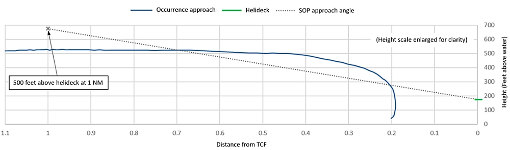
CHO’s visual approach procedure did not include any intermediate progress targets (e.g., specific altitude or groundspeed at a certain distance from facility), typically referred to as gates. Gates will be discussed in more detail later in the report.
CHO’s SOPs did not provide any direction with regard to the use of the trim release during a visual approach. The company considered this a pilot technique issue, and allowed pilots to decide whether or not they wanted to make maximum use of ATT mode and the beeper trim switches or to depress and hold the cyclic trim release. Some CHO pilots preferred to conduct non-coupled visual manoeuvres with the trim release button depressed. Others preferred to make maximum use of the force trim as a way of reducing pilot workload during visual approaches. Some of the pilots using the force trim would set an attitude of approximately 7.5° nose-up, using ATT mode, then either make small inputs against the force trim force gradient, or use the beeper switch for minor adjustments during the descent.
By making small adjustments against the cyclic when it is trimmed, releasing pressure on the cyclic will return the cyclic to the stick position and to the corresponding attitude it was originally trimmed to maintain. This is done so that if a pilot encounters some type of spatial disorientation, simply releasing pressure from the cyclic and applying power should result in the helicopter adopting an attitude that will permit the helicopter to climb away safely. If larger adjustments are required, those are typically done by depressing the cyclic trim release, resetting the attitude, and then releasing the trim release button.
The collective is used to control the glide path. Then, as the helicopter approaches the platform, trim release would be momentarily depressed and aft cyclic would be applied, up to a maximum of 15° nose-up for final deceleration. After the final deceleration, the cyclic force trim button can be released to maintain the new desired attitude during the final stages of the landing. This minimizes the amount of time during the visual approach that the trim release is depressed.
A review of 7 flights (including the occurrence flight) captured on the occurrence FDR, revealed that approximately 55% of the uncoupled takeoffs or landings (performed by different crews) were conducted with the cyclic trim release depressed for most, or all, of the sequence. For the remainder, the force trim was primarily on, with occasional use of the cyclic trim release button.
As part of the investigation, similar variances with regards to cyclic trim release usage were found among the various S-92A operators around the world. Some S-92A operators actively promote the use of attitude mode and beeper trim for visual manoeuvres, particularly in a DVE, to reduce pilot workload and to reduce the risk of spatial disorientation.Footnote 140,Footnote 141
1.18.3.8.4 Offshore/airborne radar approach procedures in instrument meteorological conditions and/or at night
CHO’s SOPs stated that the offshore/ARA procedure was to be used for offshore approaches in IMC and/or at night. According to the CARs, IMC exists when the meteorological conditions are below the minima specified in CARs Subpart 602.
CHO’s offshore/ARA procedure was a TC-approved instrument procedure that allowed a helicopter to conduct a pilot-monitored approach to an offshore installation in IMC. The offshore/ARA procedure was flown fully coupled “until the aircraft is visual and decelerated for landing. The RALT [RADALT] shall remain coupled until the landing pilot commences his descent to the helideck.”Footnote 142 According to CHO’s SOPs, “crews will normally fly a maximum of 2 IMC approaches at destination.”Footnote 143
The offshore/ARA procedure flown to the TCF was normally conducted into wind, and started 7.0 NM from the facility. Pilots had to remain at or above 800 feet ASL until crossing the FAF, which is 5.0 NM from the facility. Passing the FAF, the pilots used the collective/heading trim beeper switch to descend to the minimum descent altitude, which in this situation was the helideck height plus 50 feet (i.e., 225 feet RADALT).
At 3.0 NM, airspeed was set to a maximum of 55 knots groundspeed in order to stabilize the groundspeed before the aircraft reached 1.5 NM from the facility.
During a daytime offshore/ARA procedure with groundspeed at or below 60 knots, the missed approach point (MAP) was 0.5 NM from the facility. At 0.5 NM from the MAP, heading mode was selected so that it could be used to turn toward the helideck if visual or turn away if a missed approach was required.
If the PM visually acquired the helideck at the MAP, the PM would call “visual” and direct the PF toward the helideck. When the helicopter was approximately 0.5 NM from, and heading toward, the helideck, the indicated airspeed and heading modes were disengaged and cyclic would be used to further reduce the groundspeed and maintain the proper track. The SOPs stated that a 3-4° nose-up attitude would provide the required deceleration from 55 knots groundspeed.Footnote 144 The SOPs also noted that “[a]s the helicopter decelerates through translational lift (20-40 KIAS), there is a tendency for the nose pitch attitude to increase […]”Footnote 145 The investigation determined that this nose pitch attitude increase did not require much correction and/or anticipation by the pilot.
At 0.25 NM, the helicopter should be decelerating through approximately 30 knots groundspeed. The SOPs also instructed pilots to maintain a minimum closure rate of 15 knots groundspeed until visual cues were adequate to safely control the rate of closure.Footnote 146
As the helicopter approached the helideck, it remained coupled to RADALT until the sight picture was achieved for a normal descent to the helideck. Once the sight picture was intercepted, RADALT would be decoupled by pressing the decouple button on the cyclic or by the PM deselecting it on the mode selector panel when directed to do so.
According to CHO’s SOPs, if the pilots obtained adequate visual reference with the facility before the MAP and the ceiling was at least 300 feet above the minimum descent altitude, the pilot could carry out a VMC transition to landing.Footnote 147 The SOPs stated that “[a]fter control is transferred to the landing Pilot, the approach pilot continues to monitor the instruments passing relevant verbal information such as altitude, vertical speed, air/ ground speed and attitude until the landing pilot calls ‘Committed’.”Footnote 148 Therefore, if during an offshore/ARA procedure, the pilots acquired visual reference with the facility and the clouds were based no lower than 525 feet RADALT, the SOPs permitted the pilots to continue visually without the use of AFCS holds.
1.18.3.8.5 Missed approach procedures
According to CHO’s SOPs, a go-around from 0.5 NM or further on an offshore/ARA procedure was carried out by using the heading mode to turn 45° in the missed approach direction and then selecting “Go Around” to initiate a climb.Footnote 149,Footnote 150 If the helicopter was inside 0.5 NM, it would be coupled to RADALT only. In that situation, the pilots would lower the nose slightly (2.5° nose down on the attitude indicator) and use the cyclic to turn away from the facility. Once the airspeed had increased above 50 KIAS (VMINI), the PF would engage “Go Around” to initiate the climb.Footnote 151
The SOPs stated that the helicopter must climb to at least 800 feet ASL before turning to set up for another approach or to proceed to the missed approach airport.Footnote 152
The SOPs did not specifically address a situation where a missed approach was required while conducting a visual approach.
The investigation determined that some S-92A operators have unwritten policies prohibiting pilots from aborting a missed approach in order to attempt a visual approach. In one particular case, a company implemented this informal policy following an incident where pilots aborted a missed approach and attempted to conduct a visual approach in a DVE. During the attempted approach, control difficulties were encountered as a result of the reduced visual cues and the helicopter descended inadvertently.
1.18.3.8.6 Standard operating procedures for degraded visual environments
Some offshore helicopter operators have SOPs specific to operating in a DVE. At the time of the occurrence, CHO’s SOPs made no reference to DVE operations. Following the occurrence, however, CHO revised its VMC offshore approach procedure and added a definition of DVE that stated that this environment “occurs when flying in VMC conditions but visual cues available to the pilot are not sufficient to maintain the proper flight path during flight and/or landing.”Footnote 153 The revision cited “fog obscuring the water surface” and “no visible horizon” as examples of a DVE.
1.18.4 HeliOffshore approach path management guidelines
HeliOffshore is “the global safety-focused association for the offshore helicopter industry.”Footnote 154 It was founded in 2014 and represents over 100 organizations that work in and provide services to the offshore industry, including more than 50 helicopter operators. CHO had been a member of HeliOffshore since 2015.
One of HeliOffshore’s areas of interest is approach path management. It has identified 5 elements considered critical to the conduct of a safe stabilized approach:
- Energy state;
- Approach briefing;
- Go-around management;
- Monitoring procedures; and
- Use of automation.Footnote 155
Of particular relevance to this occurrence is energy state. Energy state refers to the combined effects of airspeed, rate of descent, pitch attitude, and power setting. According to HeliOffshore, there have been many incidents involving a low-energy state below 500 feet above landing elevation or inside 0.5 NM from the facility. This suggests that continuous monitoring of enery state is necessary, rather than achieving a single point in space to be considered stable. To reduce the risk of a low-energy-state descent, one S-92A operator has established a requirement for engine torque to be greater than 40% by 300 feet above the landing spot.
HeliOffshore recommends the maximum use of standard repeatable approach profiles, which enhance monitoring and the detection of deviations. For instance, HeliOffshore’s guidance provides an example of a 5° descent profile (Figure 17), which is not intended to be flown as an instrument approach; rather, it provides a standardized approach format that can be flown both day and night VMC.Footnote 156 This approach profile, which is flown at a constant 45-knot groundspeed until 0.4 NM, requires a descent rate of approximately 350 fpm.
According to one operator’s SOPs that uses the standard approach, at each 0.2 NM increment along the approach path, standard calls are made, including distance to go, groundspeed (with indication of “fast” or “slow”, if applicable), and approach profile ( high or low). This helps increase situational awareness and reduces the risk of spatial disorientation. At 0.4 NM, the pitch attitude is increased by approximately 5° to achieve the desired 10–15 knot groundspeed as the helicopter approaches the landing decision point.
The investigation identified that some S‑92A operators have adopted HeliOffshore’s 5° profile for both day and night visual approaches. According to one S‑92A operator that uses this profile, the constant groundspeed and shallow descent alleviates the need for pitch changes, making it easier to assess if the approach angle is being maintained. By maintaining a constant groundspeed and pitch attitude, the descent angle is then controlled with the collective. In addition, the approach can mostly be flown without pressing the cyclic trim release.
![Example of a defined 5° profile (Source: HeliOffshore, <em>Operational Effectiveness – Approach Path Management Guidelines</em>, Issue 01, Version 3.0 [July 2017], p. 10.)](/sites/default/files/eng/rapports-reports/aviation/2019/a19a0055/images/a19a0055-figure-17.jpg)
For day DVE or night offshore approaches, HeliOffshore recommends a profile similar to Figure 18. This procedure shares some similarities to an offshore/ARA procedure.
![Example of day degraded visual environment or night approach (Source: HeliOffshore, <em>Operational Effectiveness – Approach Path Management Guidelines</em>, Issue 01, Version 3.0 [July 2017], p. 11.)](/sites/default/files/eng/rapports-reports/aviation/2019/a19a0055/images/a19a0055-figure-18.jpg)
HeliOffshore’s approach path management guidanceFootnote 157 includes a number of recommendations, which have been adopted by some offshore helicopter operators. Some of the recommendations that are most pertinent to this occurrence include:
- For an offshore approach, at 0.5 NM from the helideck there should be a gate along with a configuration and stabilization crosscheck. Continuing past this gate should only occur if stable, otherwise go around. Before reaching a gate, the PM shall check and verbalize that the required criteria are met. If the criteria are met, the PM shall call “0.5—stabilized” and the PF shall reply “checked”. If any of the criteria are not met at the gate, the PM will call “not stabilized, go around” and the PF will respond “going around”.
- Energy state criteria should be established in the COM. This includes specifying a minimum power setting below a minimum speed. If the power decreases below the prescribed minimum power setting, it would require an immediate go-around.
- Continuous monitoring of energy state is more important than achieving a single point along the approach.
- Operators are encouraged to include standard calls for normal operations and deviations from normal flight profiles in SOPs.
- Operators should ensure that operations manuals clearly explain procedures for the use of automation, and identify where the potential for mode confusion exists.
As highlighted earlier in the report, there has been a shift in recent years away from the use of informal patter in favour of formal gates with specific criteria which must be confirmed and verbalized. According to a number of HeliOffshore’s operator members, the elimination of informal patter enhances the PM’s ability to monitor the progress of the flight, interpret information, identify deviations, and intervene as appropriate. It is also HeliOffshore’s position that patter can become a distraction, increases the risk of non-standard phraseology, and can lead to non-relevant areas of discussion.
1.18.5 Previous occurrences
Offshore helicopter operations are often conducted far from land, in challenging weather and/or lighting conditions, and without on-site support to assist pilot decision making. Between 2014 and 2018, there were 47 offshore helicopter accidents worldwide; 23 of which were fatal, resulting in 120 fatalities.Footnote 158 According to HeliOffshore, the following 3 categories were responsible for ⅔ of the 23 fatal accidents during that period:
- Controlled flight into terrain or water (32%);
- Non-powerplant system or component failure or malfunction (22%); and
- Loss of control in flight (16%).Footnote 159
In recent years, there have been a number of occurrences related to DVE where the helicopter ended up in an undesired aircraft state while the cyclic trim release button was depressed and held. In 2011, the TSB investigated an occurrence involving an S-92A that experienced an inadvertent descent on departure.Footnote 160 In that occurrence, the PF depressed and held the cyclic trim release button during a departure in IMC conditions from an offshore facility. Shortly after entering cloud, the PF made a large, rapid aft cyclic input just before the cyclic trim button was released and the go-around mode was engaged. This caused the helicopter to enter a nose-high, decelerating pitch attitude. The PF attempted to manually recover from the nose-high attitude by depressing the cyclic trim release button. However, the PF made an unintentional aft cyclic input that caused the airspeed to drop below VMINI and the aircraft to enter a 23° nose-high unusual attitude. The PF, subtly incapacitated (possibly due to spatial disorientation) did not lower the nose of the helicopter and apply collective to recover from the nose-high unusual attitude. The pilots were able to arrest the descent once they descended below the 200-foot AGL cloud base by pulling 132% engine torque. The descent was arrested 38 feet above the water.
In 2006, the United Kingdom Air Accidents Investigation Branch (AAIB) investigated an occurrence in which an Aerospatiale SA365N Dauphin 2 struck the surface of the sea while attempting a night offshore helideck landing in poor weather conditions. All 5 passengers and both crew members died.
The approach profile in the occurrence suggested problems assessing the correct descent angle due to limited visual cues available. The investigation report pointed out that
[t]he approach was flown essentially by reference to visual cues. In dark, overcast conditions, it is likely that some cues were degraded or absent. For example, without a distinct horizon the assessment of pitch attitude and approach angle (by reference to the depression of the deck below the horizon) would be compromised. Without textural cues in the ground plane (in this case the sea surface), judgement of pitch attitude and approach angle by inference from textural perspective would also be compromised, as would the appreciation of the range to the deck.Footnote 161
The AAIB determined that the PF was depressing and holding the cyclic trim release button and introduced large control inputs (resulting in up to 38° nose-down pitch). According to the report, depressing and holding the cyclic trim release button
had the effect of losing any straight and level datum and increased the likelihood of inappropriate control inputs being made […] the use of FTR [force trim release] would have allowed large attitudes to be commanded with little tactile feedback to the crew.Footnote 162
More recently, in 2014, an AgustaWestland AW139 crashed at night during foggy conditions, fatally injuring all 4 occupants. The investigation determined that the pilot attempted to manually control the helicopter by depressing the trim release button on the cyclic and the trim release trigger on the collective. Shortly after lifting off vertically into the dark and the fog, the helicopter pitched progressively nose-down until impacting the ground.Footnote 163
1.18.6 Human performance considerations
1.18.6.1 Pilot decision making
Effective decision making involves gaining an accurate understanding of the situation, appreciating the implications of the current situation, formulating one or more plans and contingencies, then implementing a course of action. A number of factors affects this process.
An important aspect of the decision-making process is a person’s mental model.Footnote 164 The mental model is largely dependent on the person’s understanding of the circumstances, expectations about the future, and past experience. People use their past experience and their knowledge to rapidly categorize the situation they are experiencing and make judgments.Footnote 165 As a pilot develops experience in novel situations, those situations and the course of action selected create potential matches for future decisions.
If time is available, pilots can collect more information to maximize their situational awareness, help them consider the implications of the current situation, and project into the future to consider the outcome of potential courses of action. However, in situations where there is real or perceived (self-imposed) time pressure, experienced pilots tend to quickly compare the current situation to their past experience and select the course of action perceived to most likely be successful, rather than work through multiple options.Footnote 166
In many cases, experts will be able to make an appropriate match between the current situation and a previous one. However, in some circumstances, it can lead to decisions based on an inaccurate or incomplete understanding of the situation, of the implications of the situation, or of alternative courses of action available. If a higher-risk decision results in a positive outcome, it can cause an individual to become more relaxed toward higher-risk behaviours, making it more likely that they will repeat these behaviours in future.Footnote 167,Footnote 168
Studies show that “pilots tend to underestimate the likelihood of loss of control and overestimate their ability to continue to control the aircraft if visual references are lost.”Footnote 169 Similarly, pilots who deliberately accept increased risk (e.g., operating in a DVE) tend to have a greater risk tolerance, experience less anxiety in that situation, and perceive the risk as being relatively low.Footnote 170 A misjudgment of risk may lead to inappropriate decisions and unsafe behaviour; risk perception can lead to at-risk behaviour.
Organizational factors can also directly or indirectly influence pilot decision making. SOPs directly support pilot decision making by providing pilots with what the company considers to be predetermined successful solutions for specific situations. The SOPs establish expectations with regard to acceptable levels of risk for pilots to use as a frame of reference when required to make an operational decision.
Pilot decision making can also be influenced by the norms that may develop within an organization. In an effort to meet organizational goals, well-intended behaviours that incrementally increase risk may emerge over time. For this reason, it is important that organizations reinforce the importance of adherence to SOPs and identify informal practices that increase risk level.Footnote 171
1.18.6.2 Attentional narrowing
Pilots operate in a complex environment in which there are multiple sources and types of information to monitor. Because there are limits to human attention, pilots must prioritize carefully to ensure that relevant information is not overlooked.
Workload is a function of the number of tasks that must be completed within a given amount of time. If the number of tasks that must be completed increases, or if the time available to complete those tasks decreases, then workload increases. As workload increases, it places greater cognitive demands on the pilot. These increased cognitive demands can adversely affect a pilot’s ability to perceive and evaluate cues from the environment, and may result in attentional narrowing.Footnote 172,Footnote 173
Attentional narrowing occurs when
the individual is focusing all conscious attention on a limited number of environmental cues to the exclusion of others of a subjectively equal or higher detectability, or of a more immediate priority.Footnote 174
The relevant cues may be available; however, individuals experiencing high workload tend to limit their attention to the stimuli they perceive to be most important or most relevant to the task at hand.Footnote 175 Likewise, attentional narrowing is more likely to occur when there is a high motivational intensity or a heightened state of arousal, or stress.Footnote 176 If a pilot places greater importance on external cues, it can draw their attention away from the flight instruments, resulting in degraded situational awareness and potentially allowing deviations to go undetected.Footnote 177,Footnote 178
In a study involving 15 accidents, inaccurate perception accounted for 72% of the breakdowns in situational awareness.Footnote 179 Because attentional narrowing can lead to inaccurate perception, it represents a significant risk in complex, high-risk domains such as aviation.Footnote 180
To reduce the likelihood of attentional narrowing, pilots must continually evaluate their situation. This involves scanning relevant sources of information, such as cockpit displays, to ensure an accurate perception of the situation and to identify whether the plan is working out as expected or whether a change in the plan is required. In a multi-crew aircraft, communication from other crew members can be critical in recognizing and overcoming the effects of attentional narrowing.
1.19 Useful or effective investigation techniques
Not applicable.
2.0 Analysis
2.1 General
There was no indication that an aircraft system malfunction contributed to this occurrence. As a result, the analysis will focus on the operational and human factors that contributed to the inadvertent descent during an attempted visual approach to the Thebaud Central Facility (TCF) platform.
In addition, the analysis will address some organizational factors related to standard operating procedures and flight data monitoring, enhanced ground proximity warning systems, and cockpit voice recorders, with the objective of improving aviation safety.
2.2 Inadvertent descent
2.2.1 Unstable approach
According to the performance charts, approximately 39% engine torque was required for a 500 fpm descent at 60 knots indicated airspeed (KIAS). Therefore, as the airspeed decreased on final approach, more than 39% engine torque was required to keep the rate of descent less than 500 fpm. However, in this occurrence, the power was set to approximately 27% engine torque and an aft cyclic input was applied to reduce the helicopter’s forward speed and resulted in a peak nose-up attitude of almost 17°.
Due to the high nose-up pitch attitude, the helicopter’s airspeed began to decrease and the helicopter started descending rapidly. This placed the helicopter, which was already on the back side of the S-92A power curve, at least 10% engine torque below the required power setting for the helicopter’s initial approach airspeed. As a result, the helicopter entered a low-energy state; namely, the combination of low airspeed, high rate of descent, nose-up pitch attitude, and low power setting.
The helicopter’s low-energy state went undetected by the flight crew, who were focused on the helideck, sitting above the fog and in an area without a discernible horizon. The lack of visual cues during the approach in a degraded visual environment (DVE) made it more difficult for the pilots to recognize that the helicopter was descending rapidly, with increasing amounts of left sideslip due to unintentional left cyclic input. As a result, the helicopter quickly exceeded Canadian Helicopters Offshore’s (CHO’s) stabilized approach rate of descent limit (i.e., 500 fpm).
Finding as to causes and contributing factors
The helicopter’s approach became unstable due to an inadvertent low-energy, high-rate-of-descent flight profile.
Shortly after recovering from the inadvertent descent during the approach to the TCF, a second inadvertent descent occurred as the helicopter reached 1350 feet radar altitude (RADALT). At that time, the flight crew was attempting to reconcile what had just happened and determine what systems had been lost during the event. Because of this, the flight crew experienced a momentary lapse of attention that allowed an inadvertent descent rate to develop. As the flight crew established that the helicopter was still controllable, the pilots recognized the inadvertent descent and corrective action was taken.
2.2.2 Vortex ring state
As the helicopter descended below 250 feet RADALT, it was in a steep, 800 fpm descent, at very low airspeed, with power being applied. This combination of conditions created a situation highly conducive to vortex ring state (VRS), at a critical point on the approach—on short final, only 100 feet above the helideck.
When the pilot flying (PF) instinctively increased the collective to reduce the helicopter’s rate of descent, that action exacerbated the situation and the helicopter’s rate of descent rapidly increased to 1800 fpm. This left the pilots with very little time (about 3 seconds) to recognize what was happening and to attempt to recover before the helicopter descended into the fog.
Once in the fog, the pilots took aggressive action (govertorquing the engine) which, in combination with the helicopter’s unintentional translation sideways to the right, caused the helicopter to exit VRS at as low as 70 feet RADALT and prevented the helicopter from impacting the water. Although VRS did not cause the helicopter to become unstable on approach, it did contribute to how close the helicopter got to the water (13 feet) during the descent into and through the fog layer.
The VRS that the helicopter entered during this occurrence highlights the importance of strict adherence to stabilized approach criteria, as well as careful cross-checking and monitoring of flight instruments, especially in a DVE.
Finding as to causes and contributing factors
The application of power while in a steep, low airspeed, high rate of descent condition caused the helicopter to enter VRS. This contributed to the helicopter’s rapid descent into and through the fog layer, bringing the helicopter to within 13 feet of the water.
2.2.3 Attentional narrowing
During an offshore visual approach, the PF relies primarily on the visual cues in the environment, combined with regular cross-checks of the flight instruments. In a DVE, effective instrument cross-check and monitoring are particularly important due to the lack of visual references to help the PF maintain positive control of the helicopter, and to reduce the risk of spatial disorientation.
As the helicopter rolled out on final for a visual approach, it was closer and lower than prescribed by CHO’s standard operating procedures (SOPs), and faster than usual for its proximity to the TCF. In addition, the PF was sitting in the left-hand seat, so he did not have a good view of the TCF until the helicopter rolled out on final. This left the pilots, particularly the PF, with significantly less time to assess the helicopter’s rate of closure and to establish a stabilized approach.
This non-standard approach condensed the time available to the PF, who was required to apply fairly aggressive control inputs (i.e., aft cyclic and 27% engine torque) to begin the descent and slow down, from a position well inside the normal start point for a visual approach. These control inputs, which were carried out without the benefit of force trim, in a DVE, increased the PF’s workload considerably.
As the helicopter descended, both pilots’ attention was focused primarily on the helideck, which was surrounded by cloud and sitting above a layer of fog. When the PF initially increased the helicopter’s pitch attitude to almost 17° nose-up, the pilot monitoring (PM) detected it and made the appropriate callout to inform the PF. At that point, workload inside the cockpit increased further because valuable time was lost while the PF attempted to correct, and the PM monitored, the nose-high pitch attitude, while still continuing the approach in a DVE.
Due to this attentional narrowing, the priority placed by the pilots on the outside visual cues (the helideck), and then on the helicopter’s excessive nose-up pitch attitude, caused critical flight instruments to be excluded from the pilots’ instrument cross-check. In particular, the pilots did not recognize or perceive the high rate of descent (which peaked at 1800 fpm), the low engine torque (27%), and low airspeed (less than 30 KIAS), or that control inputs put the helicopter in a left sideslip (up to 40°). The combination of these factors resulted in an unstable approach that went undetected until after the helicopter had entered the fog bank below the helideck, 25 seconds after the autopilots were disengaged to begin the final descent.
Finding as to causes and contributing factors
The pilots experienced attentional narrowing due to increased workload while attempting a non-standard offshore visual approach in a DVE. This led to a breakdown in the pilots’ instrument cross-check, which prevented the timely recognition that the approach had become unstable.
2.2.4 Use of force trim in a degraded visual environment
When strong visual cues are present, pilots can easily manoeuvre the helicopter with the cyclic trim release button depressed. However, as seen in Royal Canadian Air Force (RCAF) studies and aircraft manoeuvring manuals, as well as previous accident investigations, pilot workload increases and accuracy decreases when pilots attempt to fly with the cyclic trim release depressed while operating in DVEs. In such an environment, the use of force trim reduces pilot workload and increases safety margins by providing the pilot with limited hands-off capability and a detent position that is set for a known pitch/bank attitude.
In this occurrence, the PF depressed and held the cyclic trim release button to hand-fly a non-standard visual approach in a DVE. The lack of visual cues during the approach would have presented significant challenges in terms of attitude control (pitch, bank, and yaw), sight picture (approach angle), altitude assessment (height above the water), and judging rate of closure (speed). By depressing and holding the trim release, the overall effectiveness of the automatic flight control system (AFCS) was reduced, because there would be no artificial feel (due to the magnetic brake being disengaged) or trim detent position to assist the PF in recognizing the amount of cyclic being applied. This lack of artificial feel, combined with the inadequate visual cues beneath, around, and behind the helideck, increased pilot workload making it more difficult for the PF to accurately fly the desired flight profile. As a result, there was a nose-high attitude of almost 17°, an excessive rate of descent, and an increasing left sideslip while on final.
The combination of these conditions put the helicopter in a flight regime that was highly conducive to, and resulted in, the helicopter entering VRS and descending into the fog layer.
Finding as to causes and contributing factors
Depressing and holding the cyclic trim release button, while operating in a DVE, increased pilot workload and contributed to control difficulties that resulted in an unstable approach that developed into VRS.
Neither the S-92A rotorcraft flight manual (RFM) nor CHO’s SOPs warned of the potential hazards associated with, or offered recommendations for, the use of the trim release button under conditions such as DVE. Both the manufacturer and the operator considered the use of the cyclic trim release button to be one of pilot preference. Therefore, in the absence of specific guidance from the manufacturer related to trim release usage, there is nothing to prevent or discourage S-92A pilots from depressing and holding the trim release when conducting visual manoeuvres in a DVE. As a result, it is likely that pilots will continue to use the trim release in a DVE without a full understanding of the risks, placing themselves and their passengers at risk.
In addition to the manufacturer’s role in ensuring the safety of flight, there is an expectation that operators will identify areas of risk and implement SOPs to mitigate the associated hazards. For example, some S-92A offshore operators have implemented SOPs regarding trim release usage to ensure that company pilots employ the most appropriate level of AFCS augmentation. Likewise, some RCAF aircraft standard manoeuvre and operations manuals include similar guidance and/or direction.
At the time of the occurrence, CHO’s SOPs did not include procedures or recommendations related to the use of the cyclic trim release in a DVE. In addition, there was no standardization with respect to the way CHO pilots employed the trim release during visual manoeuvres. This lack of standardization resulted in variability and reduced effectiveness in the way company S-92A pilots used the trim release button in the offshore environment.
Finding as to risk
If manufacturers’ flight manuals and operators’ SOPs do not include guidelines for the use of the cyclic trim release button, it could lead to aircraft control problems in a DVE due to the sub-optimal use of the AFCS.
2.2.5 Spatial disorientation and degraded visual environment
At the time of the occurrence, the helideck sat above a layer of fog and the rig was surrounded by cloud. These conditions made it impossible for the pilots to fly with reference to the surface, as required by section 602.115 of the Canadian Aviation Regulations (CARs). In addition, there was no discernible horizon visible due to the extensive cloud cover around the TCF. As a result, the conditions at the time met the criteria for instrument meteorological conditions (IMC), representing a DVE because of the lack of visual cues available to assist with spatial orientation (e.g., position and rate of change of position) and aircraft control. This would have made it difficult for the pilots to accurately assess height, speed, and distance. In the absence of the horizon and the water surface, the TCF, and more specifically the helideck relative to the offshore platform and obstacles, became the primary visual reference.
As seen in this occurrence, in the absence of other references for approach path management, both pilots’ attention was primarily focused on the helideck, and less attention was placed on ensuring a stable approach.
Finding as to causes and contributing factors
At the time of the occurrence, IMC existed. This created a DVE that was highly conducive to spatial disorientation and provided inadequate cues to permit a visual approach to the TCF.
When the final descent began, the PF had a clear line of sight to the helideck. Having previous experience in similar weather conditions, the PF did not anticipate having difficulties conducting a visual approach. However, as the descent commenced, the helicopter quickly exceeded the stabilized approach criteria. The absence of strong visual cues to assist with vertical and lateral flight path guidance made it difficult for the PF to maintain proper spatial orientation.
Based on the PF’s control inputs (almost 17° nose-up attitude and left cyclic resulting in left sideslip), it is apparent that he was experiencing a degree of spatial disorientation and was unaware that the helicopter was descending rapidly, at slow airspeed, with significant left sideslip. When the PF detected that the helicopter was descending too quickly, at approximately 250 feet RADALT, he applied power to reduce the descent. However, the aircraft encountered VRS and descended quickly into the fog layer.
When the helicopter descended into the fog bank, and the PF lost visual contact with the helideck, it did not match the PF’s understanding of the situation. The PF then had to process this new, unexpected information. As the PF observed the rate of descent rapidly increasing, to a peak of 1800 fpm, it would have significantly increased the cognitive demands on him and contributed to the delay in him notifying the PM that he had lost visual reference with the helideck.
Although the PF made an attempt to initiate a go-around, the PM initially provided verbal cues and then physically assisted the PF during the final stages of the descent, when the collective was rapidly increased while adjusting the cyclic to establish a wings-level go-around attitude.
Finding as to causes and contributing factors
The PF was likely subtly incapacitated due to spatial disorientation following the helicopter’s rapid, unexpected descent into the fog layer. As a result, recovery action was initially delayed until the pilots acquired visual contact with the water and the collective was rapidly increased to arrest the descent.
2.2.6 Crew coordination
Once both pilots realized that the helicopter had inadvertently descended, at a very high rate of descent, into the fog bank, their focus was on preventing impact with the water. The PM physically assisted the PF to level the helicopter and arrest the descent at a low altitude over the water. However, the PM did not formally assume control of the aircraft at the time. It was after the descent had been arrested that the PM formally took control using the standard terminology of “I have control”. He then used the TCF as a reference to commence a visual climbout.
In this occurrence, both pilots were at the controls during the final portion of the descent. Despite this, the crew was able to successfully arrest the descent, avoiding impact with the water. However, from a crew resource management standpoint, it is important to recognize that a positive transfer of control reduces the risk of pilots making opposing control inputs. This is particularly important when one pilot may be suffering from some type of incapacitation, where it could interfere with or prevent the appropriate flight control inputs being made.
Finding as to risk
If pilots of a multi-crew aircraft are making control inputs at the same time during an undesired aircraft state, there is a risk of exacerbating the recovery effort and reducing safety margins.
2.3 Pilot decision making
The flight had been delayed multiple days due to low clouds and poor visibility. It is likely that the pilots’ decision to attempt and continue with the visual approach in DVE was influenced, either directly or indirectly, by a number of factors:
- After 2 missed approaches, the goal (i.e., landing on the helideck) suddenly appeared achievable.
- The helicopter had sufficient fuel to attempt a third approach, but was close to minimum diversion fuel.
- The helideck was clearly visible to the pilots.
- The pilots knew that the helideck could quickly become obscured once again.
- The helicopter was clear of clouds between layers, with no immediately apparent perceived risk.
- Both pilots were very experienced offshore helicopter pilots.
- Both pilots had previously been in similar weather conditions.
- It was not uncommon for CHO pilots to conduct visual approaches over a layer of fog.
- The company’s SOPs permitted pilots to continue visually during an offshore/airborne radar approach (ARA) procedure if they broke out at least 300 feet above the minimum descent altitude .
- The pilots had considerable confidence in each other’s flying abilities.
- Helicopter pilots are accustomed to intercepting final approaches from different height/distance combinations.
It is likely that the combination of these factors contributed to the pilots’ decision to attempt the visual approach.
Fully aware that only limited time was available to attempt a visual approach, the pilots would have quickly compared the current situation to previous situations in search of a successful strategy. Having been in similar meteorological conditions situations before, the pilots were confident in their abilities to safely complete the visual approach. In addition, the pilots were aware that certain elements of their situation paralleled some aspects of the offshore/ARA procedure. As a result, when they made the decision to abort the missed approach and fly a non-standard visual approach, it seemed reasonable based on the factors listed above. However, by electing to conduct an expedited approach, the pilots did not allow themselves much time (they were on a downwind for approximately 8 seconds before turning final) to fully consider the risk of conducting a visual approach in IMC/DVE conditions, or to consider other alternatives that better reflected their SOPs and ensured adequate safety margins. This led the pilots to underestimate the risks of continuing with their planned course of action although it did not comply with company SOPs or the CARs.
Finding as to causes and contributing factors
In an attempt to complete their assigned task within self-imposed time constraints, the pilots’ decision-making process was influenced by their past experience and comfort with each other. As a result, the pilots attempted a non-standard visual approach in a DVE, without thoroughly considering the risks or alternative options.
2.4 Standard operating procedures
2.4.1 Stabilized approaches
CHO’s SOPs identified 6 conditions for a stabilized approach. Of those 6 conditions, the only 2 criteria that could be objectively applied to a visual approach were that the helicopter must be configured for landing, and it must have a maximum rate of descent of 500 fpm, unless a higher rate had been briefed. Unlike some operators that specify minimum torque values during the approach (e.g., minimum 40% by 300 feet above the landing spot), CHO’s SOPs made no reference to energy state in its stabilized approach criteria. As a result, CHO’s procedures did not address one of the critical elements of a stabilized approach identified by HeliOffshore, an organization of which CHO was a member. Since there were no established criteria to be monitored, it increased the risk of a low-energy state developing and going undetected, as seen in this occurrence.
Although not included in CHO’s definition of a stabilized approach, the SOPs also stated that the approach must be stable by 300 feet above the landing elevation, in visual meteorological conditions (VMC). Otherwise, an immediate go-around was required. CHO had not adopted HeliOffshore’s recommended practice of requiring crews to check and verbally confirm that the approach was stable at specific gates (e.g., 300 feet above landing elevation).
Establishing gates and specific criteria to confirm,creates standards that help direct pilots’ attention to the critical information during an approach. Doing this helps pilots identify deviations early, maximizes their situational awareness, and helps ensure that only stabilized approaches are continued to landing. In this occurrence, the helicopter’s rate of descent (520 fpm and increasing) exceeded the stabilized approach criteria as it passed 300 feet above the landing elevation, 6 seconds after beginning the descent. However, in the absence of a formal procedure to verify a stabilized approach, the pilots’ attention was not drawn to flight instruments that would have provided the information necessary to recognize that an immediate go-around was required.
Finding as to causes and contributing factors
CHO’s SOPs provided flight crew with insufficient guidance to ensure that approaches were being conducted in accordance with industry-recommended stabilized approach guidelines.
2.4.2 Deviations from standard operating procedures
Since the helicopter was in clear air between layers following the second missed approach, the pilots did not perceive the early turnout, which was contrary to CHO’s SOPs, as presenting an increased risk. However, by levelling off at 500 feet RADALT and beginning the right turn to assess the conditions, the pilots lost sight of the TCF behind them during a portion of the turn. This resulted in the helicopter rolling out at approximately 1 nautical mile (NM), with the TCF off the helicopter’s right side. When the turn to final was completed and the descent commenced, the helicopter was at 0.43 NM from the TCF at a higher-than-normal airspeed. This significantly reduced the time available, compared to CHO’s visual approach SOPs, for the flight crew to assess position and rate of change of position leading up to, and during, the final descent to ensure a stable approach.
When the descent was initiated, pilot workload increased quickly as more aggressive handling was required to acquire the appropriate sight picture in close proximity to the TCF. Shortly after commencing the descent, the rate of descent exceeded 500 fpm, indicating an unstable approach according to CHO’s SOPs. The approach remained unstable until the helicopter descended into the fog bank.
This occurrence highlights how deviations from company SOPs that are perceived to be minor, in isolation or in combination, can inadvertently create a sequence of events that increases risk to unacceptable levels.
Finding as to risk
If pilots deviate from SOPs, it can lead to an inadvertent increase of pilot workload and reduce safety margins to unacceptable levels.
2.4.3 Degraded visual environment procedures
In the offshore helicopter environment, pilots often face rapidly changing weather, ranging from VMC to IMC, and a wide range of conditions in between. In recent years, the offshore helicopter community has taken steps to address some of the risks of flying in adverse weather conditions by producing industry-recommended approach path guidance recommendations. These recommendations include standard approach profiles, such as profiles for operations in DVEs.
At the time of the occurrence, CHO did not have SOPs relating to DVEs in place to assist pilot decision making. The lack of explicit direction with regards to operating in a DVE may have made it difficult for pilots to fully understand the risks associated with attempting the visual approach in IMC.
Following the occurrence, CHO revised the day VMC offshore approach procedure to include considerations relating to DVEs. In that revised procedure, CHO indicated that DVEs occur in VMC and includes such weather phenomena as fog obscuring the water surface and no visible horizon. However, these conditions are consistent with Transport Canada’s interpretation of IMC. As has been noted previously in the industry, this suggests that CHO management may not have recognized the importance of clearly defining the regulatory requirements for conducting visual flight rules flight in uncontrolled airspace, which could have contributed to company pilots attempting visual approaches in IMC conditions.
Finding as to risk
If company SOPs do not clearly define and establish procedures for operating in a DVE, there is a risk that pilots will assume an unacceptable level of risk by attempting to conduct visual manoeuvres in IMC and/or a DVE.
2.4.4 Approach briefings
According to CHO’s SOPs, a visual approach briefing was required to identify who would conduct the landing, as well as the transition to final, the landing point, and the type of landing. There was no requirement to brief emergency actions, stabilized approach gates, or other operational risks that may be present. As a result, the SOPs did not clearly establish positive, easily identifiable targets to confirm an offshore visual approach was stable.
In this occurrence, the lack of comprehensive visual approach briefing criteria may have played a role in the flight crew’s decision to attempt an offshore visual approach to a helideck sitting above a layer of fog and surrounded by cloud.
Finding as to risk
If approach briefings lack sufficient detail, there is a risk that operational hazards will go unaddressed before attempting an approach.
2.4.5 Conflicting information in standard operating procedures
Although not contributory to the occurrence, the investigation identified discrepancies and overlapping information in CHO’s SOPs that could have led to confusion in the cockpit. Some of those examples include:
- CHO’s SOPs stated that an approach was to be stabilized by 300 feet above the landing elevation in VMC. This section of the SOPs also stated that an immediate go-around was to be initiated if the helicopter was not stabilized by 250 feet above the landing elevation in VMC. This created the potential for confusion, as it was unclear whether an immediate go-around was to be initiated if the helicopter was not stabilized by 300 or by 250 feet above the landing elevation in VMC.
- CHO’s SOPs stated that, when passengers were on board, a rate of descent in excess of 500 fpm, other than on an instrument final approach, was considered an abnormal rate of descent that must be called out. It also stated that the maximum rate of descent for a stabilized approach was 500 fpm. However, in another section of the SOPs, it stated that a rate of descent greater than 600 fpm necessitated a standard callout. As a result, a pilot may have been uncertain whether they were required to make a rate of descent callout if the rate of descent exceeded 500 fpm or 600 fpm.
Finding as to risk
If a company’s SOPs contain conflicting or ambiguous procedures, there is an increased likelihood of procedural errors that can reduce safety margins to unacceptable levels.
2.5 Canadian Helicopters Offshore helicopter flight data monitoring
CHO had a safety management system that used helicopter flight data monitoring (HFDM) as a proactive tool for identifying operational risks present in everyday operations. To achieve this, the program aimed to identify areas where flight crews were deviating from the SOPs. A review of the parameters monitored revealed that there were several offshore approach parameters; however, the distance for the final leg of a visual approach, or the glide path angle flown were not parameters that were monitored. As a result, the company had no way of determining if its pilots were adhering to the visual approach procedure, and adhering to the CHO’s stabilized approach criteria.
The investigation determined that some pilots did not always adhere to the prescribed visual approach final distance, nor was the 4.7° glide path always followed. The company’s HFDM program did not actively use available aircraft FDR and health and usage monitoring system (HUMS) data to detect these types of deviations from company SOPs.
Finding as to risk
If a company’s flight data monitoring program does not monitor specific parameters established in the SOPs, it reduces the company’s ability to proactively identify trends that could reduce safety margins.
2.6 Enhanced ground proximity warning system
In this occurrence, the helicopter inadvertently descended with a very high rate of descent into the fog bank at low airspeed with the landing gear extended. Despite this, the helicopter’s enhanced ground proximity warning system (EGPWS), which is designed to prevent inadvertent collision with terrain, did not alert the crew to the situation.
As previously identified in TSB Air Transportation Safety Investigation A11H0001, Mode 1 of the Honeywell Mk XXII is inhibited on the S-92A. This mode is not inhibited on any other helicopter equipped with the Mk XXII. According to Sikorsky, the decision to inhibit Mode 1 was based on a high number of false alarms received during certification testing in 2002. The following year, Honeywell updated the Mode 1 envelope to address these concerns about nuisance alerts. Despite this, Mode 1 has remained inhibited on the S-92A for over 17 years, leaving operators without EGPWS protection during a common phase of flight for offshore helicopter operators.
As seen in this occurrence, the descent fell within the Mode 1 envelope and would have provided the pilots with a “SINKRATE” aural alert as the helicopter descended through 225 feet RADALT and a “PULL UP!” aural alert as it descended below the height of the TCF’s helideck (174 feet AGL). As a result, if Mode 1 had been enabled on the S-92A, it would have warned the flight crew of the excessive rate of descent before it entered the fog bank, increasing the crew’s situational awareness about the severity of the situation. Although it is unlikely that the Mode 1 alert would have prevented the inadvertent descent into the fog, it would have given the flight crew critical information about the descent, making it readily apparent that immediate, positive action was required.
In March 2018, Sikorsky decided to enable Mode 1, but this is only scheduled to happen in late 2021 or early 2022, with the release of avionics management system (AMS) version 11. This software update (EGPWS-036) will include an expanded Mode 1 envelope, the newly developed Mode 7, and several other enhancements. Once implemented, these enhancements should significantly reduce the likelihood that an inadvertent descent goes undetected. However, until AMS version 11 is installed, the S-92A’s EGPWS capabilities will remain reduced due to the absence of Mode 1. In addition, Mode 7 will not be certified on the S-92A due to concerns about the use of the “CHECK AIRSPEED” aural alert.
In addition to Mode 1 being disabled, with the landing gear down, Mode 3 protection ceases when the helicopter’s airspeed drops below 50 KIAS. The decision to use 50 KIAS as the lower airspeed threshold for Mode 3 with the gear down was deemed an acceptable compromise in order to avoid false alarms during the repositioning of the helicopter in the airport environment or for rejected takeoffs. In addition, the manufacturer’s decision was influenced by the belief that if an inadvertent descent occurred during takeoff, it would not be accompanied by a significant reduction in airspeed. However, this creates a gap in the coverage provided by the S-92A’s EGPWS.
As seen in this occurrence, if an inadvertent descent develops with the landing gear down and the airspeed below 50 KIAS, the EGPWS will provide no warning against controlled flights into terrain (CFIT), regardless of the rate of descent. There is no rate of descent threshold established for EGPWS purposes to differentiate between a controlled descent and an inadvertent descent that could result in a CFIT accident.
Finding as to causes and contributing factors
The S-92A’s EGPWS provides no warning of an inadvertent descent at airspeeds below 50 KIAS when the landing gear is down. As a result, the EGPWS did not alert the flight crew of the impending risk of CFIT.
In 2016, the TSB issued a recommendation calling for terrain awareness and warning systems for commercial helicopters that operate at night or in instrument meteorological conditions. At the time of report writing, it is still not required by regulation and it is unclear how and if TC will take action to address the intent of this recommendation.
Finding as to risk
Until EGPWS or helicopter terrain awareness and warning systems become mandatory for Canadian commercial helicopters that operate at night or in IMC, flight crew and passengers aboard these flights are at increased risk of CFIT.
2.7 Cockpit voice recorder
In this occurrence, the personnel involved in downloading flight data recorder (FDR) data, at the manufacturer’s request, did not have a thorough understanding of the CVR system or the requirements for the preservation of recorder information stipulated in subsection 8(1) of the Transportation Safety Board Regulations. As a result, valuable information was lost that could have assisted the investigation.
Finding as to risk
If operators do not implement adequate measures to preserve CVR audio and FDR data following a reportable occurrence, there is a risk that potentially valuable information will be lost.
3.0 Findings
3.1 Findings as to causes and contributing factors
These are conditions, acts or safety deficiencies that were found to have caused or contributed to this occurrence.
- At the time of the occurrence, instrument meteorological conditions existed. This created a degraded visual environment that was highly conducive to spatial disorientation and provided inadequate cues to permit a visual approach to the Thebaud Central Facility.
- In an attempt to complete their assigned task within self-imposed time constraints, the pilots’ decision-making process was influenced by their past experience and comfort with each other. As a result, the pilots attempted a non-standard visual approach in a degraded visual environment, without thoroughly considering the risks or alternative options.
- Canadian Helicopters Offshore’s standard operating procedures provided flight crew with insufficient guidance to ensure that approaches were being conducted in accordance with industry-recommended stabilized approach guidelines.
- Depressing and holding the cyclic trim release button, while operating in a degraded visual environment, increased pilot workload and contributed to control difficulties that resulted in an unstable approach that developed into vortex ring state.
- The helicopter’s approach became unstable, due to an inadvertent low-energy, high-rate-of-descent flight profile.
- The pilots experienced attentional narrowing due to increased workload while attempting a non-standard offshore visual approach in a degraded visual environment. This led to a breakdown in the pilots’ instrument cross-check, which prevented the timely recognition that the approach had become unstable.
- The S-92A’s enhanced ground proximity warning system provides no warning of an inadvertent descent at airspeeds below 50 knots indicated airspeed when the landing gear is down. As a result, the enhanced ground proximity warning system did not alert the flight crew of the impending risk of controlled flight into terrain.
- The pilot flying was likely subtly incapacitated due to spatial disorientation following the helicopter’s rapid, unexpected descent into the fog layer. As a result, recovery action was initially delayed until the pilots acquired visual contact with the water and the collective was rapidly increased to arrest the descent.
- The application of power while in a steep, low-airspeed, high rate of descent condition caused the helicopter to enter vortex ring state. This contributed to the helicopter’s rapid descent into and through the fog layer, bringing the helicopter to within 13 feet of the water.
3.2 Findings as to risk
These are conditions, unsafe acts or safety deficiencies that were found not to be a factor in this occurrence but could have adverse consequences in future occurrences.
- If manufacturers’ flight manuals and operators’ standard operating procedures do not include guidelines for the use of the cyclic trim release button, it could lead to aircraft control problems in a degraded visual environment due to the sub-optimal use of the automatic flight control system.
- If pilots of a multi-crew aircraft are making control inputs at the same time during an undesired aircraft state, there is a risk of exacerbating the recovery effort and reducing safety margins.
- If pilots deviate from standard operating procedures, it can lead to an inadvertent increase of pilot workload and reduce safety margins to unacceptable levels.
- If company standard operating procedures do not clearly define and establish procedures for operating in a degraded visual environment, there is a risk that pilots will assume an unacceptable level of risk by attempting to conduct visual manoeuvres in instrument meteorological conditions and/or a degraded visual environment.
- If approach briefings lack sufficient detail, there is a risk that operational hazards will go unaddressed before attempting an approach.
- If a company’s standard operating procedures contain conflicting or ambiguous procedures, there is an increased likelihood of procedural errors that can reduce safety margins to unacceptable levels.
- If a company’s flight data monitoring program does not monitor specific parameters established in the standard operating procedures, it reduces a company’s ability to proactively identify trends that could reduce safety margins.
- Until enhanced ground proximity warning systems or helicopter terrain awareness and warning systems become mandatory for Canadian commercial helicopters that operate at night or in instrument meteorological conditions, flight crew and passengers aboard these flights are at increased risk of controlled flight into terrain.
- If operators do not implement adequate measures to preserve cockpit voice recorder audio and flight data recorder data following a reportable occurrence, there is a risk that potentially valuable information will be lost.
4.0 Safety action
4.1 Safety action taken
4.1.1 Canadian Helicopters Offshore
As a result of this occurrence, Canadian Helicopters Offshore took the following safety action:
- Voluntarily ceased all flight operations until a better understanding of the occurrence was possible.
- Conducted a review of cockpit voice recorder (CVR) and flight data recorder (FDR) preservation procedures.
- Conducted a review of the company's Emergency Response Plan.
- Conducted an internal safety management system (SMS) investigation to identify circumstances that contributed to the occurrence.
- Developed a degraded visual environment (DVE) approach procedure for inclusion in company standard operating procedures (SOPs).
- Developed a return to flight training package consisting of:
- additional crew resource management (CRM) training addressing DVEs, cockpit gradient, and decision making;
- simulator ground school including power management, and the new DVE approach procedure; and
- simulator session on the new DVE approach procedure.
- Briefed the HeliOffshore forum to raise awareness and support safe industry operations.
As of last quarter 2019, CHO had voluntarily requested the Minister to suspend its air operator certificate since the company no longer had any aircraft in its possession, nor did it have any ongoing contracts.
This report concludes the Transportation Safety Board of Canada’s investigation into this occurrence. The Board authorized the release of this report on It was officially released on
Appendices
Appendix A – Screenshot from occurrence animation (flight parameters)
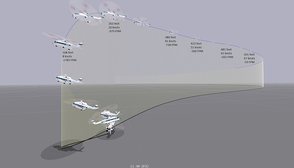
Source: TSB
Appendix B – Estimated vertical profile during recovery
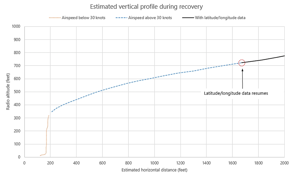
Source: TSB
Appendix C – Occurrence flight compared with Mode 7 alert boundary
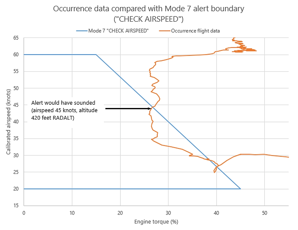
Source: TSB
Appendix D – Summary of TSB occurrences from 2004 to 2020 in which cockpit voice recorder data were overwritten
Table D1. Cockpit voice recorder overwrites found in TSB occurrences (30-minute and 2-hour cockpit voice recorders), 2004–2020
| Year | TSB occurrences with 30-minute CVR overwrites | Number | TSB occurrences with 2-hour CVR overwrites | Number |
|---|---|---|---|---|
| 2004 | A04O0237 A04P0319 |
2 | None | 0 |
| 2005 | A05F0047 A05W0059 A05W0010 A05W0222 |
4 | None | 0 |
| 2006 | A06C0204 A06O0295 |
2 | None | 0 |
| 2007 | None | 0 | A07C0106 | 1 |
| 2008 | A08A0147 A08C0108 A08O0189 A08Q0051 A08A0151 A08O0036 A08O0333 A08W0001 |
8 | A08C0164 A08Q0171 |
2 |
| 2009 | A09O0117 | 1 | None | 0 |
| 2010 | A10A0123 A10F0068 |
2 | None | 0 |
| 2011 | A11Q0042 | 1 | A11F0012 A11Q0052 A11H0001 A11O0218 |
4 |
| 2012 | A12A0009 A12Q0161 |
2 | A12O0074 A12W0005 |
2 |
| 2013 | None | 0 | A13O0045 | 1 |
| 2014 | A14A0052 | 1 | A14H0001 A14O0165 A14H0002 A14Q0088 |
4 |
| 2015 | A15O0015 A15O0142 A15F0111 A15W0008 |
4 | A15F0165 A15W0041 |
2 |
| 2016 | None | 0 | A16O0021 A16C0044 A16W0020 A16O0158 |
4 |
| 2017 | None | 0 | A17O0184 A17A0063 A17W0148 |
3 |
| 2018 | A18A0088 | 1 | A18P0119 A18W0081 |
2 |
| 2019 | A19F0184 A19O0117 |
2 | A19A0055 A19W0094 A19F0176 |
3 |
| 2020 | None | 0 | A20A0001 | 1 |
| Total | 30 | 29 |
Source: TSB
| Continued flight | Power being applied after shutdown | |
|---|---|---|
| 30-minute CVRs | 14 | 16 |
| 2-hour CVRs | 11 | 18 |
| Percentage of all overwrites | 42% | 58% |
Appendix E – S-92A cruise performance chart (occurrence conditions)
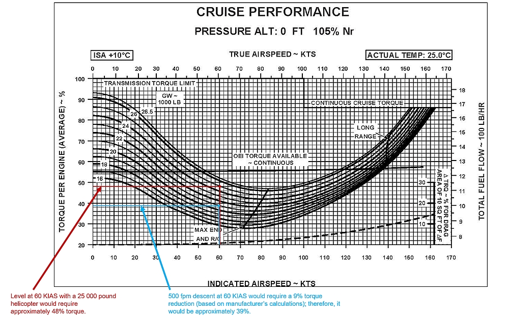
Source: Sikorsky, FAA Approved Rotorcraft Flight Manual: Sikorsky Model S-92A, SA S92A-RFM-003, Revision 8 [02 May 2012], Part 2, Section III: Supplemental Performance Data, Figure 3-13, p. III-1-18, with TSB annotations
Appendix F – Representation of a degraded visual environment on final approach
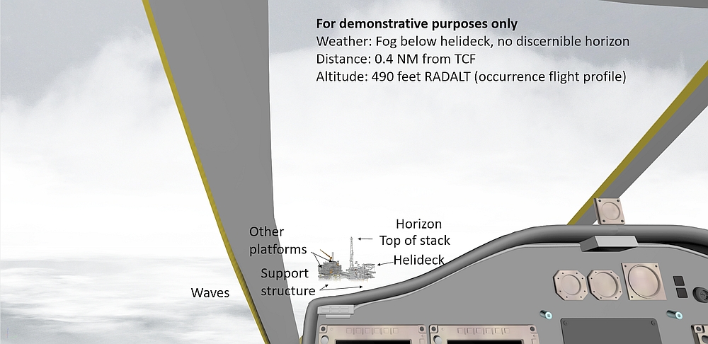
Source: TSB
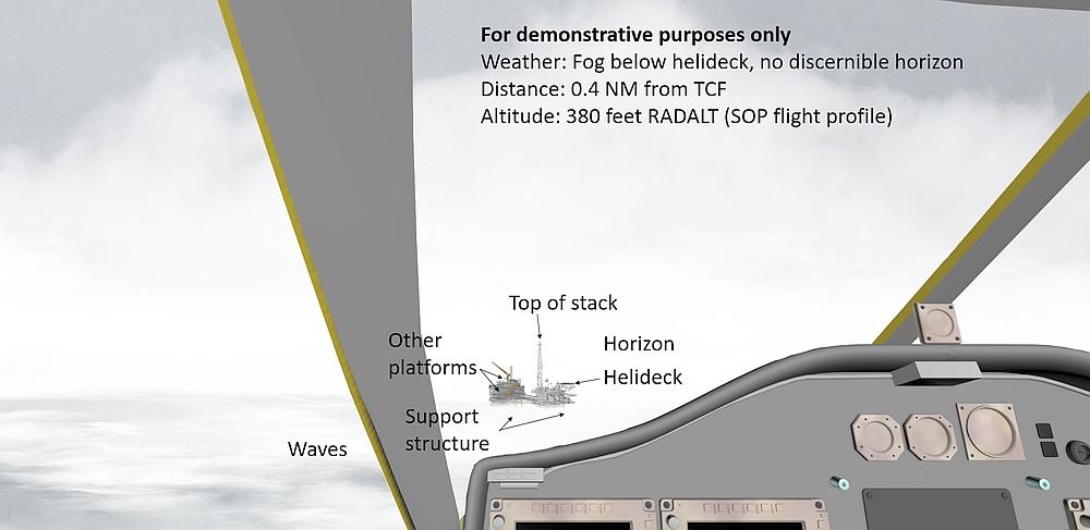
Source: TSB
Appendix G – Representation of clear weather conditions on final approach

Source: TSB
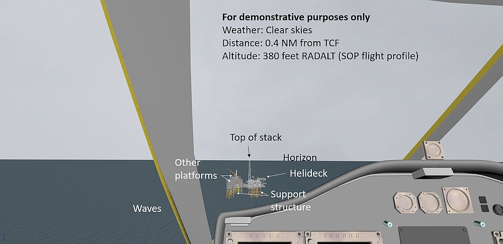
Source: TSB
Glossary
- AAIB
- Air Accidents Investigation Branch (United Kingdom)
- AC
- alternating current
- AFCS
- automatic flight control system
- AGL
- above ground level
- AHRS
- attitude and heading reference system
- AMS
- avionics management system
- APU
- auxiliary power unit
- ARA
- airborne radar approach
- ASL
- above sea level
- ATT
- attitude hold mode
- AVC
- active vibration control
- CARs
- Canadian Aviation Regulations
- CFD
- coupled flight director
- CFIT
- controlled flight into terrain
- CHL
- Canadian Helicopters Limited
- CHO
- Canadian Helicopters Offshore
- COM
- company operations manual
- CVR
- cockpit voice recorder
- CYHZ
- Halifax/Stanfield International Airport, Nova Scotia
- DC
- direct current
- DVE
- degraded visual environment
- EFVS
- enhanced flight vision systems
- EGPWS
- enhanced ground proximity warning system
- EICAS
- engine indication and crew alerting system
- FAF
- final approach fix
- FDR
- flight data recorder
- FMS
- flight management system
- fpm
- feet per minute
- HFDM
- helicopter flight data monitoring
- HTAWS
- helicopter terrain awareness and warning system
- HUMS
- health and usage monitoring system
- IFR
- instrument flight rules
- IMC
- instrument meteorological conditions
- inHg
- inches of mercury
- KIAS
- knots indicated airspeed
- M
- magnetic
- MFD
- multi-function display
- MPFR
- multi-purpose flight recorder
- NM
- nautical mile
- Nr
- main rotor rpm
- OFP
- operational flight plan
- PF
- pilot flying
- PFD
- primary flight display
- PM
- pilot monitoring
- RADALT
- radar altitude
- RCAF
- Royal Canadian Air Force
- RFM
- rotorcraft flight manual
- SAR
- search and rescue
- SAS
- stability augmentation system
- SM
- statute mile
- SOPs
- standard operating procedures
- T
- true
- TC
- Transport Canada
- TCF
- Thebaud platform
- TSB
- Transportation Safety Board of Canada
- VFR
- visual flight rules
- VMC
- visual meteorological conditions
- VMINI
- instrument flight minimum speed
- VRS
- vortex ring state