
Air transportation safety investigation report A22O0060
Loss of control and collision with terrain
Diamond Aircraft Sales USA Inc.
Diamond Aircraft Industries GmbH DA 42 NG, N591ER
London Airport, Ontario
The Transportation Safety Board of Canada (TSB) investigated this occurrence for the purpose of advancing transportation safety. It is not the function of the Board to assign fault or determine civil or criminal liability. This report is not created for use in the context of legal, disciplinary or other proceedings. See Ownership and use of content.
-
Table of contents
Summary
At approximately 1329 Eastern Daylight Time on 25 May 2022, the Diamond Aircraft Industries GmbH DA 42 NG aircraft (United States registration N591ER, serial number 42.081) departed Runway 09 at London Airport, Ontario, on a local test flight following a major overhaul that had been completed at the Diamond Aircraft Industries Inc. facilities at the airport.
During the takeoff, when the aircraft became airborne, the aircraft yawed abruptly to the left. The pilot attempted to correct for the unexpected yaw but had difficulty maintaining directional control of the aircraft. The pilot attempted to make an emergency landing on Runway 27; however, during the approach, the pilot continued to have difficulty controlling the aircraft and instead attempted to land on Taxiway A before ultimately landing on the grass between the runway and the taxiway.
When the aircraft touched down hard on the grass, the rudder and the left-wing aileron mass balance weight broke off. The landing gear collapsed, and the aircraft slid to a stop approximately 265 feet from the initial impact point. The pilot was not injured. The aircraft was substantially damaged.
During the initial examination of the aircraft following the incident, it was discovered that the rudder moved in the opposite direction of pilot input.
1.0 Factual information
1.1 History of the occurrence
On 01 October 2021, the occurrence aircraft, a Diamond Aircraft Industries GmbH DA 42 NG, arrived at the Diamond Aircraft Industries Inc. Approved Maintenance Organization (AMO) located at London Airport, Ontario (CYXU). The aircraft was to undergo a 2000-hour inspection, including a mechanical and structural inspection, and general refurbishing. The maintenance activities of this major overhaul included, but were not limited to, partial disassembly of the aircraft, replacement of both engines, overhaul of both propellers, and replacement of all rudder cables. During the work, it was noted that the rudder cable guide tubes were worn, so they were also replaced. An annual inspection of the aircraft was also scheduled to be completed.
On 25 May 2022, following the completion of all of the maintenance work, the occurrence aircraft departed Runway 09 at CYXU at approximately 1329Footnote 1 for a test flight. During the takeoff, when the aircraft became airborne, it yawed abruptly to the left.
The pilot attempted to correct for the unexpected yaw by adding full right rudder and full right aileron input, but he could not maintain directional control of the aircraft. Despite the right control inputs, the aircraft continued to yaw and bank to the left at an estimated height of about 500 feet above ground level (AGL).
The pilot initially intended to return to land on Runway 09 and, believing that there was a problem with one of the engines, began adjusting the throttle levers to troubleshoot the situation. When this did not resolve the problem, the pilot considered the possibility that the controls were providing reverse direction to pilot input.
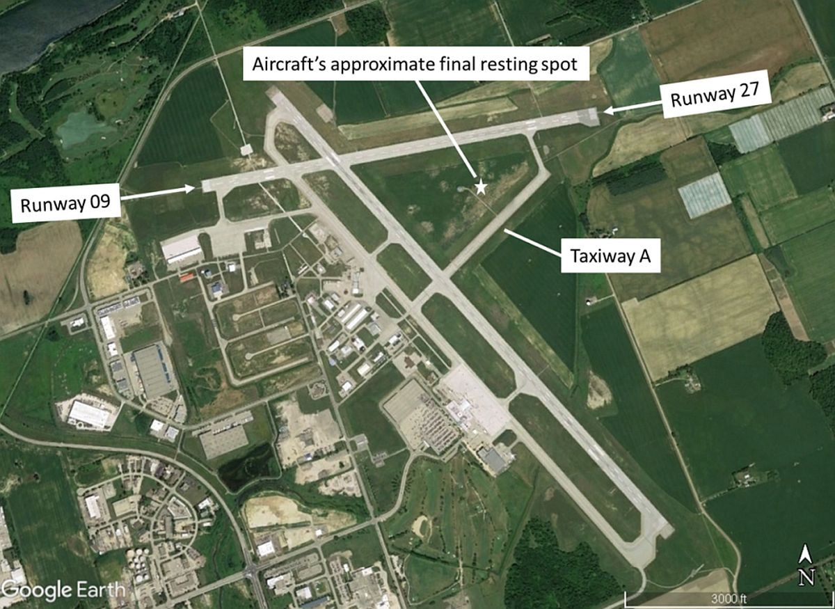
The pilot declared an emergency with air traffic control (ATC) and then intended to land on Runway 27; however, he could not regain complete control of the aircraft and instead attempted to land in a southwest direction on Taxiway A. He eventually landed on the grass between the runway and Taxiway A (Figure 1). On touchdown, the landing gear collapsed and the aircraft slid approximately 265 feet before coming to a stop.
In the initial examination of the aircraft following the incident, it was discovered that during the recent maintenance activities, the rudder guide tubes were installed running parallel to each other instead of crossing over at the rear of the fuselage as prescribed in the Airplane Maintenance Manual. Consequently, when the rudder cables were threaded through these guide tubes, they were connected to the same side of the rudder lower mounting bracket in the rear of the aircraft instead of to the opposite side. Despite subsequent maintenance and pre-flight inspections, the incorrect installation went unnoticed, resulting in the rudder moving in the opposite direction of pilot input.
1.2 Injuries to persons
The pilot was alone on board. He was not injured.
1.3 Damage to aircraft
The aircraft was substantially damaged. The rudder and the left-wing aileron mass balance weight broke off and the landing gear collapsed. There was damage to both propellers, engine nacelles, and various sections on the underside of the fuselage.
1.4 Other damage
There was no other damage.
1.5 Personnel information
1.5.1 Pilot
The occurrence pilot held both a commercial pilot licence issued by Transport Canada (TC) and a commercial pilot certificate issued by the Federal Aviation Administration (FAA) of the United States (U.S.). He also held an aircraft mechanic certificate issued by the FAA with airframe and powerplant ratings, and he had a valid inspection authorization from the FAA, which allowed him to perform inspections, such as an annual inspection, on a U.S.-registered aircraft and approve its return to service.
All of the pilot’s licences and certificates were valid in accordance with their respective existing regulations.
The pilot did not work on the aircraft during the overhaul and refurbishment, but he did sign off the FAA annual inspection.
1.5.2 Aircraft maintenance personnel
Although the maintenance work performed on the occurrence aircraft involved several aircraft maintenance engineers (AMEs), technicians, and apprentice technicians over the course of the overhaul, only 2 AMEs, 1 technician, and 1 apprentice AME were involved in the replacement of the rudder cable guide tubes and rudder cables, which took place in early January 2022.
1.5.2.1 Aircraft maintenance engineers
The AME who certified both the inspection of the rudder cable replacement and the final maintenance release of the aircraft held a valid AME licence issued by TC, with an M1 rating. He also held an aircraft certification authority (ACA) issued by Diamond Aircraft Industries Inc.’s AMO. An ACA is an authorization granted by the AMO permitting an AME to sign a maintenance release pertaining to work done on the aircraft or parts to be installed on it.Footnote 2 He was the team lead on the weekend shift and verbally approved the request by the apprentice AME to replace the rudder cable guide tubes.
The second AME signed the final independent inspection of the flight controls and engine controls. He held a valid AME licence issued by TC, with an M1 rating. He also held an ACA issued by Diamond Aircraft Industries Inc.’s AMO.
1.5.2.2 Technician
The technician who signed for the rudder cable replacement task was authorized to perform work on the aircraft. He also held a shop certification authority (SCA), an authorization issued by the AMO permitting a person who does not hold an AME licence to sign a maintenance release pertaining to parts intended for installation on an aircraft.Footnote 3 The technician held a foreign licence and was in the process of obtaining a Canadian AME licence. He had many years of experience working as an AME for foreign airlines and was the weekday shift team lead for the maintenance work done on the occurrence aircraft. He assigned maintenance tasks according to the work order and supervised the work that was done. He completed the rudder cable installation the day after the apprentice AME had replaced the guide tubes.
1.5.2.3 Apprentice aircraft maintenance engineer
The apprentice AME (called “the apprentice” from now on) had completed AME training at a TC-approved school. He had started working at the Diamond Aircraft Industries Inc.’s AMO in October 2021, and had performed various maintenance tasks, which were recorded in his AME logbook. He was not authorized under an SCA or an ACA and was not trained in company procedures or applicable regulatory requirements under the AMO.
The apprentice discovered the worn rudder cable guide tubes on the occurrence aircraft during his weekend shift, then removed and replaced them with new ones.
1.6 Aircraft information
The Diamond Aircraft Industries GmbH DA 42 NG is a 4-seat, low-wing, retractable-gear, all-composite aircraft. It is powered by 2 Austro E4B diesel engines with 3-bladed MT hydraulic constant-speed propellers.
| Manufacturer | Diamond Aircraft Industries GmbH |
|---|---|
| Type, model, and registration | DA 42, DA 42 NG, N591ER |
| Year of manufacture | 2006 |
| Serial number | 42.081 |
| Total airframe time | 5371.6 |
| Engine type (number of engines) | Reciprocating Austro E4B (2) |
| Propeller (number of propellers) | MT 3-bladed (2) |
| Maximum allowable take-off weight | 4189 lb (1900 kg) |
| Recommended fuel types | Jet A, Diesel |
| Fuel type used | Jet A |
There were no recorded defects outstanding at the time of the occurrence.
The aircraft’s weight and centre of gravity were within the prescribed limits.
1.7 Meteorological information
The weather was suitable for the flight under visual flight rules. The hourly aerodrome routine meteorological report issued at 1300 for CYXU indicated winds from 110° true at 15 knots. Visibility was 15 statute miles. There were broken clouds at 3400 feet and 15 000 feet AGL. The temperature was 20 °C and the dew point was 12 °C. The altimeter setting was 30.20 inches of mercury.
Weather was not considered to be a factor in this occurrence.
1.8 Aids to navigation
Not applicable.
1.9 Communications
Not applicable.
1.10 Aerodrome information
Not applicable.
1.11 Flight recorders
The aircraft was not equipped with a flight data recorder or a cockpit voice recorder, nor was either required by regulation.
1.12 Wreckage and impact information
Following the occurrence, TSB investigators examined the aircraft at the Diamond Aircraft Industries Inc.’s facilities at CYXU and observed that the rudder cable guide tubesFootnote 4 had been installed incorrectly.
The system description section of the Airplane Maintenance Manual (AMM) explains that the “two fuselage cables go through Teflon tubes in the rear fuselage. The cables attach to the rudder lower mounting bracket. The cables cross over each other in the rear fuselage”Footnote 5,Footnote 6 (Figure 2).
This configuration ensures the correct fuselage cable routing to the rudder so that the left rudder pedal controls the left rudder deflection, and the right rudder pedal controls the right rudder deflection. However, in this occurrence, the guide tubes were installed straight through, not crossed over. Consequently, pressing the right rudder resulted in a rudder deflection to the left, and vice versa. The improper cable routing did not affect the nose wheel steering system, which uses its own linkages attached to the rudder yoke assembly.
![Rudder controls in the fuselage, with location of crossing guide tubes circled. The solid red lines in the circle indicate the actual installation (cables not crossed), while the dashed lines indicate the proper installation (cables crossing over). (Source: Diamond Aircraft Industries GmbH, <em>DA 42 NG Airplane Maintenance Manual</em>, Revision 5 [22 December 2021], Section 27-20: Flight Controls - Rudder, p. 9, with TSB annotations)](./images/a22o0060-figure-02.jpg)
1.13 Medical and pathological information
According to information gathered during the investigation, there was no indication that the pilot’s performance was affected by medical or physiological factors.
1.14 Fire
There was no indication of fire either before or after the occurrence.
1.15 Survival aspects
Not applicable.
1.16 Tests and research
Not applicable.
1.17 Organizational and management information
1.17.1 Diamond Aircraft Industries
1.17.1.1 General
Diamond Aircraft Industries GmbH is a privately owned company that designs aircraft and aeronautical products, manufactures aircraft and components, and provides maintenance services to the aviation industry. The company is headquartered in Wiener Neustadt, Austria, and the Canadian branch, Diamond Aircraft Industries Inc., is located in London, Ontario. The Canadian branch holds both a Manufacturer Certificate and an AMO Certificate issued by TC for activities conducted under Canadian Aviation Regulations (CARs) Subpart 561 (Manufacturer of Aeronautical Products) and Subpart 573 (Approved Maintenance Organizations).
Diamond Aircraft Industries Inc. is authorized to manufacture complete aircraft and aeronautical products for the DA 20 series and DA 40 series of aircraft, as well as the DA 62 aircraft. The AMO Certificate authorizes Diamond Aircraft Industries Inc. to conduct maintenance in the following categories:
- aircraft (non-specialized work on small airplanes)
- avionics (auto-flight and radio systems)
- instruments
- non-destructive testing
- propeller
- structures
- welding
The AMO operates separately from the manufacturing portion of the company, but under the same certificate number. At the time of the occurrence, approximately 34 maintenance personnel worked at the AMO.
1.17.1.2 Maintenance personnel
Diamond Aircraft Industries Inc.’s AMO employs both AMEs and technicians.
AMEs are those individuals who hold a valid TC AME licence and can be authorized to hold an ACA. Their typical duties include regular aircraft maintenance, certification of work accomplished, and overseeing and mentoring technicians.
Technicians are those individuals who have either completed a TC-approved AME training program or hold a valid foreign AME licence. Technicians without a foreign licence can participate in an apprenticeship program to become an AME. This requires them to complete certain maintenance tasks, acquire a predetermined amount of experience, and write knowledge-based exams before TC will issue an AME licence. There is no requirement for technicians to become licensed AMEs if they do not wish to. Experienced technicians can be issued an SCA provided that they meet the company’s requirements and have all the required training.
Apprentices work under the direct supervision of an AME or a more senior technician while they gain experience on the aircraft.
1.17.1.3 Training and authorization
1.17.1.3.1 General
The company’s TC-approved Maintenance Policy Manual (MPM) states that
[a]ll staff will undergo training when they first begin work with the AMO. The initial training will consist of:
- Familiarization with the organization’s policies, procedures and any necessary regulatory requirements.
- Human factors
- Parts traceability and identification
- Maintenance Safety
- Occurrence reportingFootnote 7
1.17.1.3.2 Apprentice aircraft maintenance engineer
The MPM lists the apprentice’s responsibilities as follows:
- To carry out maintenance, repair and modifications as directed by an AME or the PRM [person responsible for maintenance]
- To assist with any function of the AMO when directed
- To work in accordance with this manual and all procedures.
- To ensure any data, instructions, guidance or other documentation used is the most current revision for the purpose of the task being carried out.
- To complete worksheets for work accomplished.
- To report unserviceable items to the Person Responsible for Maintenance.Footnote 8
The apprentice who replaced the rudder cable guide tubes had been hired at the end of October 2021. The investigation determined that, while he received some on-the-job training, there was no record of him having received the training listed in the MPM at the time he performed the work on the rudder control system in January 2022.
1.17.1.3.3 Aircraft certification authority and shop certification authority holders
The MPM describes the training required for ACA and SCA holders, and states the following:
prior to the issuance of an ACA/SCA, an applicant must complete a practical examination. […] The practical exam shall reflect a maintenance task considered within the scope of duties to be performed by the applicant. The exam should consist of the following:
- Demonstration of proper techniques, and industry standards to complete the task.
- Demonstration of the ability to correctly reference maintenance manuals […]
- Demonstration the ability to correctly complete aircraft technical records […].Footnote 9
Diamond Aircraft Industries Inc.’s AMO could not provide records of this required practical examination for either of the ACA or SCA holders involved in the rudder cable replacement, the independent inspection, and the maintenance release of the aircraft.
1.17.1.4 Work assignments
There are no formal company procedures for assigning maintenance tasks. Work orders are based on an agreed-upon scope of maintenance work for a specific client contract (e.g. maintenance tasks as part of aircraft overhaul).
A team lead is assigned to each aircraft along with a group of maintenance personnel, which may consist of AMEs, technicians, and apprentices. The team lead assigns tasks to the team members each day. The team lead also ensures that apprentices know how to do the assigned tasks, provides guidance as needed, and oversees the work of apprentices.
Before beginning an assigned task, maintenance team members sign in to a computer system under the work order for the aircraft. Equipment and parts used are scanned into the system to monitor inventory and client billing.
1.17.1.5 Maintenance
The maintenance procedures to be followed are detailed in the MPM, which specifies that “[a]ll maintenance shall be carried out in accordance with CAR/AWM [Canadian Aviation Regulation / Airworthiness Manual] 571 and where appropriate the regulatory requirements for the country in which the aircraft is registered.”Footnote 10
The MPM also states that “[a]ll maintenance is tracked and documented through a work order and the work orders are tracked through a log.”Footnote 11
With respect to discrepancies found during maintenance work, the MPM states:
All discrepancies discovered during the completion of the maintenance tasks shall be documented on a discrepancy sheet. The discrepancy sheet will detail:
- the type of discrepancy
- the individual that found it
- the date
- the rectification of the discrepancy
- the inspection and approval of the rectification
- the date of rectificationFootnote 12
1.17.1.6 Documentation
The relevant paperwork required to complete an aircraft overhaul, including discrepancy sheets and some specialized instructions and check sheets, is contained in a work order package. Included in the package is a set of dual inspectionFootnote 13 check sheets that Diamond Aircraft Industries Inc. uses to track all items that might require a dual inspection. To reduce the size of the completed work order package, the discrepancy sheets list only reference numbers to the relevant sections in the AMM regarding the removal, installation, and inspection of parts.
The work station is equipped with a computer where maintenance personnel can look up and print all references required for the work being completed.
The discrepancy sheet includes 3 main columns:
- Discrepancy / MX Action: provides space to write a description of the discrepancy or the maintenance task to be completed, along with a cell to be stamped or initialed by the person who identified the discrepancy;
- Rectification / MX Action: provides space to write what rectification or maintenance actions were performed, and includes a cell to indicate the reference data used for the work; and
- Certification: provides cells to be stamped or initialed by the person who performed the work, the person who inspected the work, and the person who performed the dual inspection, where applicable.
Each sheet has space for 4 items. The following statement is at the bottom of each sheet and has to be stamped and dated by the releasing ACA holder: “All discrepancies/Rectifications/MX Actions on this page have been reviewed by the releasing ACA.”Footnote 14
The investigation determined that several signatures and stamps, including some related directly to the work on the rudder, were missing throughout the work order package for the overhaul of the occurrence aircraft. In addition, numerous tasks were signed off as having been completed long after the work was accomplished. The investigation also determined that information was missing on the status of the work in progress at the end of the day when the rudder cable guide tubes were replaced. The MPM states:
A discrepancy can also include work that is only partially completed but needs to be left due to the end of shift or an assignment to other duties. This is to ensure that there is continuity of the work being carried out and that the removal of any item left out of the control of an individual can be tracked.Footnote 15
It should be noted that, while the work order package contained numerous discrepancies, the maintenance release and independent inspections signed by the respective ACA holders certifies that all work was accomplished in accordance with existing regulations.
1.17.2 Civil aviation authorities
1.17.2.1 Regulatory requirements
Table 2 presents the CARs provisions that are relevant to this occurrence.
| Provision | Text |
|---|---|
| Paragraph 571.02(1)(a) of the CARs | “[…] a person who performs maintenance or elementary work on an aeronautical product shall use the most recent methods, techniques […] that are specified for the aeronautical product in the most recent maintenance manual or instructions for continued airworthiness developed by the manufacturer of that aeronautical product.” |
| Paragraph 571.03(b) of the CARs | “A person who performs maintenance or elementary work on an aeronautical product shall ensure that […] the technical record is accurate with respect to any outstanding elements of the work performed, in particular, the need to secure any fastening device that was disturbed to facilitate the work.” |
| Paragraph 571.03(1)(g) of the CARs Standards | “[W]here a task is partially completed, a general description of any outstanding work, including the specific location of any parts/systems that have been disturbed, is to be recorded. Where the open work lists, inspection sheets or job cards used to accomplish the work clearly indicate any outstanding work, they are acceptable for meeting this requirement.” |
| Subsection 571.11(6) of the CARs | “If a maintenance release is signed by a person in respect of work performed by another person, the person signing the maintenance release must personally observe the work to the extent necessary to ensure that it is performed in accordance with the requirements of any applicable standards of airworthiness […].” |
| Subsection 573.06(1) of the CARs | “An approved maintenance organization (AMO) certificate holder shall implement a training program to ensure that persons authorized to perform or supervise the performance of any function under this Subpart are trained in respect of the regulations, the standards and the AMO procedures applicable to that function.” |
| Subsection 573.08(4) of the CARs | “Where a task undertaken by an AMO is divided into sub-tasks, the person appointed pursuant to section 573.03 shall establish a system of task control to ensure that all of the sub-tasks are completed prior to the signing of a maintenance release in respect of the completion of that task.” |
Because the occurrence aircraft was registered in the U.S., it was subject to the special conditions listed in an agreement between the FAA and TC.Footnote 16 One of the conditions applicable in this case was that “[m]aintenance and modifications must be approved for return to service in accordance with the requirements of CAR 571.10, Maintenance Release.”Footnote 17 Subsection 571.10(1) of the CARs states that
[n]o person shall sign a maintenance release […] or permit anyone whom the person supervises to sign a maintenance release, unless the standards of airworthiness applicable to the maintenance performed and stated in Standard 571 – Maintenance have been complied with […].Footnote 18
1.17.2.2 Guidance material
In addition to the regulatory requirements, TC has issued other guidance over the years related to the issue of improperly rigged engine and flight controls. These include an Airworthiness NoticeFootnote 19 and an article in the Aviation Safety – Maintainer.Footnote 20
1.7.2.3 Regulatory surveillance
In April 2020, TC conducted a targeted inspection of Diamond Aircraft Industries Inc. to assess the risks based on the level of operation during the COVID-19 pandemic. The company was identified as low risk for surveillance planning purposes given that it experienced a significant decrease in activity and reduction in staff.
In early March 2022, TC conducted a process inspection of Diamond Aircraft Industries Inc. that evaluated the regulatory requirements related to quality assurance for both the AMO Certificate and the Manufacturer Certificate. The surveillance was conducted remotelyFootnote 21 and concluded that they were both in compliance with the regulatory quality assurance requirements.
1.18 Additional information
1.18.1 Rudder cable guide tube and cable installation and inspection processes
The investigation examined the processes for the installation of the rudder cable guide tubes and rudder cables as well as the inspection to test for correct range of movement for the rudder control system.
1.18.1.1 Rudder cable guide tube installation
The rudder cable guide tubes are not normally replaced by maintenance personnel during the course of regular maintenance because they are rarely found to be defective, and there is no specific requirement to change or inspect them at regular intervals.
The AMM describes the fuselage cables and guide tubes and states that the “cables cross over each other in the rear fuselage.”Footnote 22 The rudder cables are routed immediately alongside one another in the rear fuselage.
The AMM also provides some troubleshooting guidance, which suggests that rudder stiffness or catching may be caused by the rudder cables chaffing in the guide tubes. To solve the issue, the AMM suggestsFootnote 23 to replace the rudder cables and guide tubes; however, there is no method or procedure in the AMM specific to replacing the guide tubes.
If needed, installation drawings can be requested from the manufacturing division of Diamond Aircraft Industries Inc. The DA 42 Illustrated Part Catalog, which was available to occurrence maintenance personnel, provides the part number for the guide tube material.
To install rudder cable guide tubes, one rudder cable is first removed from the aircraft. Next, the clamps securing the ends of the guide tube are loosened and the old guide tube is pulled out. New guide tube material is then guided through the fuselage, cut to length, and then secured with the clamps. The procedure is repeated for the other guide tube.
The investigation determined that during the course of the overhaul of the occurrence aircraft, an apprentice working the weekend shift was assigned the task of replacing the rudder cables on 09 January 2022. The apprentice pointed out to the weekend shift team lead, an ACA holder, that the rudder cable guide tubes were damaged and was then verbally authorized to replace them; however, neither the team lead nor the apprentice entered the guide tube discrepancy on the work order discrepancy sheet as required by the MPM.
The apprentice proceeded to remove both of the aft fuselage rudder cables, then removed the guide tubes, which can be accomplished without being able to see how they are routed through the rear fuselage. New guide tube material was obtained and the guide tubes were installed and secured.
This was the first time the apprentice changed the rudder cable guide tubes on a DA 42 and he was not aware that they had to cross over each other. The apprentice’s previous experience with rudder controls at Diamond Aircraft Industries Inc. was on a DA 20 aircraft. The rudder cables on that aircraft run parallel to each other.
The team lead who supervised the apprentice’s work on the rudder cable guide tube installation had previous experience changing the rudder cable guide tubes and cables on DA 42 aircraft and was aware that the rudder cable guide tubes crossed over. The team lead did not provide the apprentice with any reference material, such as the manufacturer’s installation drawings. The team lead also did not ensure that the apprentice knew and understood that the rudder cable guide tubes crossed over each other in the rear fuselage, as described in the AMM.
On the day the work was completed, the apprentice was being supervised by his team lead, who held an ACA.
1.18.1.2 Rudder cable installation
The AMM details the steps for replacing the rear rudder cables that run through the guide tubes. The procedure involves cutting the connectors off of one of the old rudder cables and pulling the old rudder cable out of the guide tube. A new cable is then fed through the guide tube, new connectors are installed, and the rudder cable is connected to the respective fittings. The procedure is repeated for the next cable. Once both cables have been replaced, they are adjusted to the correct tension. Two of the steps are a test for the correct range of rudder movement,Footnote 24 and an inspection of the rudder controls that have been adjusted. If required by the airworthiness authority, a duplicate inspection should also be performed.Footnote 25
The system description section in the AMM shows a detailed figure of the rudder controls in the fuselage, which includes a view of the guide tubes and dashed lines showing that they cross over each other toward the aft section of the fuselage (Figure 2, above). The system description also mentions that the rudder cables cross over in the aft section. However, the troubleshooting section, which suggests replacing the guide tubes in case of rudder control stiffness, does not refer to either the system description or the applicable figure in the same section.
In addition, the cable installation steps are for one cable at a time. The installation procedure does not specify to connect the left rudder cable to the right side of the rudder lower mounting bracket and vice versa.
As part of the overhaul of the occurrence aircraft, all rudder cables were replaced with new ones. The apprentice who was assigned to replace the rudder cables did not complete the full rudder cable installation on the day the work was assigned because the guide tubes had to be replaced first. At the end of the work shift, no information about the partial work completed or the guide tube replacement was recorded on the discrepancy sheet. This type of information is normally recorded so that the next person working on the system will have a clear understanding of the status of the work that remains to be done.
According to the work order, the replacement of the rudder cables was signed off as completed on 16 February 2022; however, the replacement was actually accomplished from 09 to 11 January 2022. The replacement of the rudder cables was conducted, and then later stamped as completed, by the team lead of the weekday shift, who held an SCA. The independent inspection was stamped as completed by an ACA holder. The investigation was unable to determine if all steps listed in the AMM, particularly the inspection of the controls that had been adjusted and a test for the correct range of movement, had been completed, given that the rudder cables did not cross in the rear fuselage.
1.18.1.3 Rudder control system test for correct range of movement
The AMM outlines the procedures for checking the rudder for correct range of movement.Footnote 26 It is very difficult to both move the rudder pedals and see the rudder move from inside the cockpit. Although not stated in the AMM or required by regulations, it should be noted that it is beneficial to have 2 people perform the check: one in the cockpit actioning the command throughout the full range of movement, and the other monitoring the surface to confirm the proper direction and full range of movement. It is important that the communication between the 2 people performing the check be clear, and both need to agree that the surface is moving in the direction commanded.
It is possible, and within the regulations to have this task performed by 1 person, but it requires devising a method, or using special tooling, to hold the pedals in the required positions and then going to the rear of the aircraft to check that the rudder has the correct position and deflection for the given step in the procedure.
The first 4 items of the AMM procedure set the aircraft up to do the checks. This includes placing the aircraft on stands to facilitate the movement of the rudder, which is connected to the nose wheel steering and more difficult to move under the weight of the aircraft. Items 5 to 7 of this check require setting the pedals in different positions to check the range and direction of travel of the rudder. The first of these steps is checking that the rudder is centred with the pedals centred. The next steps check that the rudder deflects to the left at least 24° with the pedal set fully left and then that the rudder deflects to the right at least 24° with the pedal set fully right.
The investigation determined that there was variability in the performance of the test for correct range of movement at the company. For example, the test, which benefits from having 2 people perform it, would sometimes be conducted by only 1 person. The investigation was unable to determine if special tooling was available when 1 person conducted the test alone. In addition, when conducted by 2 people, the maintenance personnel positioned at the rear of the aircraft would not always specify to the person at the controls in the cockpit which pedal to set (i.e. left or right) and observe that the rudder moved in the direction corresponding to the set rudder pedal.
In this occurrence, 1 person (the team lead) completed the rudder cable replacement and performed the check for correct range of movement by moving the rudder surface manually to check the range of deflection and then moving the rudder pedals to ensure the free movement of the system.
1.18.1.4 Independent inspection of flight control system
After work has been completed on a flight control system, such as the rudder, and the work has been certified, an independent inspection of the controls must be performed. The certification of the work and the subsequent independent inspection are referred to as the dual inspections. The MPM states the following:
Whenever maintenance performed on an aircraft disturbs the engine or flight controls an independent check of the controls shall be performed. All independent inspections shall be carried out by a properly authorized ACA/SCA with the action being recorded on the work order.
Dual Inspections shall be entered into the appropriate logbook with a maintenance release.Footnote 27
Even though the MPM is not detailed on what needs to be verified as part of an independent inspection, this section is in keeping with the requirements of CARs Standard 571.10, which provides the applicable standards of airworthiness for various types of work. With respect to work that disturbs engine or flight controls, the applicable standard of airworthiness is as follows:
That the system has been inspected for correct assembly and correct locking of any parts disturbed by the maintenance performed, including an operational check for proper sense and range of motion of the engine or flight controls has been accomplished, by at least two persons, and the technical record contains the signatures of both persons.
(amended 2010/12/30)
Information Note:
One of the signatures required by this section may be that of the person who has signed the maintenance release.Footnote 28
According to the work order discrepancy sheet, there were signatures and stamps dated 16 May 2022, indicating the dual inspections were completed. The individuals who signed for the dual inspections were qualified to do so according to the requirements of the MPM.
As previously mentioned, only 1 person conducted the test for correct range of movement during the certification of the work. However, the investigation was unable to determine whether a 2nd person was involved in the independent inspection to help with the range of movement test or whether the aircraft was on stands at the time. Neither of the inspections detected that the guide tubes were parallel to each other instead of crossed, that the rudder cables were connected to the same side of the rudder lower mounting bracket in the rear of the aircraft instead of to the opposite side, or that the rudder moved in the opposite direction of pilot input.
1.18.1.5 Annual inspection
During the course of the overhaul, the occurrence pilot, who held an FAA inspection authorization, conducted an annual inspection of the aircraft as required by the FAA. The inspection included checking the “[f]light and engine controls—for improper installation and improper operation.”Footnote 29 No discrepancies were identified by the pilot when the flight controls were inspected.
1.18.1.6 Pre-flight inspection
Before the first flight of the day, pilots are required to carry out a pre-flight inspection of the aircraft. The checklists to follow for the inspection are in the Airplane Flight Manual. Among them are an internal cabin check and walkaround of the aircraft.Footnote 30
As part of the cabin check, pilots are to “check free and correct movement up to full deflection”Footnote 31 of the flight controls. For the rudder, this item is difficult to accomplish with weight on wheels given the connection to the nose wheel steering. As well, the design of the fuselage for this aircraft and many other aircraft makes it very difficult for pilots to see the rudder move while they are moving the rudder pedals when seated in the cockpit. Properly checking the rudder for correct movement is difficult without the assistance of a 2nd person, standing outside the aircraft, to watch for correct rudder movement.
Additionally, the before takeoff checklist includes an item to check the “unrestricted free movement, correct sense”Footnote 32 of the flight controls. As previously stated, this would be hard to do for a pilot seated in the aircraft and ready for takeoff.
On the day of the occurrence, the pilot carried out the pre-flight inspection alone and did not find any discrepancies with the aircraft.
1.18.2 Human factors
1.18.2.1 Potential task errors
The rudder cable guide tube replacement and test for correct range of movement involve mechanical knowledge, maintenance rules, as well as visual and physical techniques. Both processes are therefore vulnerable to knowledge-based, rule-based, and skill-based errors.
Knowledge-based performance is largely conscious, occurring as technicians learn new situations and outcomes. As training progresses, rules will be learned to produce more regulated if-then performance. Knowledge-based and rule-based errors may occur because of previous experience or insufficient training and documented procedures. Technicians may not know how to deal with certain scenarios, they may follow rules that do not apply to the task, or they may omit rules that do apply, such as not following known procedures.
Organizational training and documented maintenance procedures are key to communicating and reinforcing required knowledge and rules. However, if such documentation and training do not accurately describe the required knowledge or rules, then the actual performance may differ from what is required. Further, if there is no system in place to capture such performance deviations, then repeated practice will serve to reinforce and strengthen such incorrect behavioural habits.
As technicians gain experience and practice, task performance will become more automatic, which enables them to develop—to some degree—the skills required to perform the actions where they respond appropriately upon perceiving relevant cues such as, for example, when A happens, B will occur. During this process, each step in the sequence automatically prompts the next step in the sequence with minimal use of attentional resources. Skill-based errors, such as not detecting that a maintenance task has not been properly completed during inspection, may occur if technicians are interrupted or if they are biased by preconditions, such as expectation and assumptions.
Performance errors can be mitigated by appropriate defences, such as suitable education, training, procedures, equipment, operating environment, scheduling, supervision, and safety management. These defences can reduce the probability of an error and detect errors should they occur.
2.0 Analysis
In this occurrence, the pilot experienced difficulties controlling the aircraft immediately after takeoff. Through the investigation, it was observed that the rudder cable guide tubes had been installed parallel to each other instead of crossing over each other and, as a result, the rudder cables moved the rudder in the opposite direction to pilot input.
This analysis examines the training provided to the apprentice aircraft maintenance engineer (called “the apprentice” from now on) involved in the work, and then focuses on the organizational factors that contributed to the incorrect installation of the rudder cable guide tubes and rudder cables, including rudder cable guide tube installation guidance and maintenance records. Next, the analysis discusses the rudder control system checks, including the range of movement tests. Finally, it examines the certification of work and, more specifically, the certification of work accomplished by another person.
2.1 Training
The apprentice who replaced the rudder cable guide tubes had joined the organization approximately 4 months before the work was performed. The investigation was unable to find any records of the apprentice receiving the initial training required by the company’s Transport Canada-approved Maintenance Policy Manual (MPM).
In addition, Diamond Aircraft Industries Inc.’s Approved Maintenance Organization (AMO) could not provide records of the practical examination for either of the aircraft certification authority (ACA) or shop certification authority (SCA) holders involved in the rudder cable replacement, the independent inspection, and the maintenance release of the aircraft.
During the replacement of the rudder cable guide tubes, the apprentice was working under the supervision of the team lead of the weekend shift. However, the apprentice had limited familiarity with the applicable company procedures and practices, such as recording incomplete work on the discrepancy sheets, and may not have known his responsibilities for maintenance performed under the AMO.
Finding as to risk
If maintenance personnel are not trained on company procedures and applicable regulatory requirements before being authorized to perform or certify maintenance, there is a risk that the aircraft will not be airworthy when it is returned to service.
2.2 Rudder cable guide tube installation
The investigation determined that the rudder cable guide tubes had been installed parallel to each other instead of crossing over in the rear of the fuselage, as specified in the Airplane Maintenance Manual (AMM). As a result, the rudder cables moved the rudder in the opposite direction of pilot input.
The apprentice involved in this occurrence had previous experience installing rudder cables on DA 20 aircraft and assumed that the rudder cables on the DA 42 were similarly run, that is, parallel to each other. When the guide tubes were removed, the apprentice did not notice that they crossed over in the rear of the fuselage, likely because he did not expect them to be. He did not ask for any guidance.
The AMM does not contain specific procedures for installing the rudder cable guide tubes. Although there were schematics and a written description indicating that the guide tubes and rudder cables crossed, the apprentice did not refer to them. In addition, the team lead of the weekend shift did not ensure that the apprentice was aware and understood that the rudder cable guide tubes crossed over each other in the rear fuselage and did not supervise the installation of the guide tubes.
The design of the aircraft is such that the guide tubes can be installed incorrectly. That is to say, the guide tubes can be installed in parallel, rather than crossing each other, without interfering with the aircraft structure or systems. For a technician without experience on this model of aircraft, the parallel installation could appear to be a normal and logical installation.
The team lead of the weekday shift completed the rudder cable installation the day after the apprentice had replaced the rudder cable guide tubes.
Findings as to causes and contributing factors
The apprentice who installed the rudder cable guide tubes did so without the aid of specific procedures, guidance, or supervision. As a result, the rudder cable guide tubes were installed incorrectly, running parallel to each other instead of crossing over at the rear of the fuselage as prescribed in the AMM.
When the rudder cables were threaded through the rudder cable guide tubes, they also ran in parallel when connected to the rudder lower mounting bracket in the rear of the aircraft. As a result, the rudder moved in the opposite direction of pilot input.
2.3 Certification of work
By signing a maintenance release on the replacement of the rudder cables, the ACA holder certified that the work met the applicable standards of airworthiness for this test. The investigation determined that the test for correct range of movement performed for the certification of the work was conducted by only 1 person, the team lead of the weekday shift, who held an SCA. Given that there were no special tooling or devices called for or used during the procedure, it would have been very difficult for 1 person to validate the correct rudder and pedal position.
The aircraft maintenance engineer who signed the maintenance release for the certification of the major overhaul work was qualified and authorized by the organization. He had extensive experience on the aircraft and had certified rudder cable replacements on the same model of aircraft multiple times in the past without experiencing any issues.
2.3.1 Certification of work accomplished by another person
In this occurrence, the rudder cable guide tube replacement and the installation of the rudder cables were performed by individuals other than the person certifying the work. The ACA holder who certified the work was not present during the performance of the work and was not aware of the guide tube replacement before certifying the work. Even though it is possible to inspect most of the work after it has been completed, there are some aspects of the rudder cable installation that may be difficult to validate due to their location on the aircraft, especially when the person certifying the work is not aware of the work performed on the system.
For the steps that are difficult or impossible to validate once the work is completed, it may be necessary for the person signing the maintenance release for the certification of the work, to observe the work being completed, to the extent necessary to ensure the work meets the applicable standards of airworthiness.
Finding as to a risk
If the person signing a maintenance release for work accomplished by another person does not observe the work to the extent necessary to ensure that it is performed in accordance with the applicable standards of airworthiness, there is a risk that the aircraft will not be airworthy when it is returned to service.
2.4 Maintenance records
The investigation determined that there were missing or incomplete maintenance records in the aircraft work package. Company policies and procedures are specific on the requirements for recording maintenance. Some of the forms and documents used by the company, such as the discrepancy sheet and dual inspection check sheet, were missing information related to the status of the work.
In addition, documentation of the rudder cable guide tube replacement was missing from the maintenance records. The task was completed as part of the rudder cable replacement, which was only partially completed at the end of the work shift. As a result, the rudder cable replacement was left for the maintenance personnel on the following shift to complete. Without records of the work performed on the system, the status of the work was unclear for the person completing the task and was misleading for the inspection and certification of the work.
Finding as to causes and contributing factors
The replacement of the rudder cable guide tubes was not recorded, likely because the overall maintenance task was incomplete at the end of the work shift. As a result, the personnel who later certified the work and conducted the independent inspection were not aware of the guide tube replacement and did not check to ensure it had been completed correctly.
2.5 Rudder control system checks
2.5.1 Inspection during certification of work
The AMM for the DA 42 NG details the procedure to test for the correct range of movement of the rudder control system. This test is required during the certification of the work and the independent inspection. The test describes the correlation between the pedal positions and the rudder surface positions. However, the investigation determined that there was variability in the performance of the test. For example, maintenance personnel positioned at the rear of the aircraft would not always specify to the person at the controls in the cockpit which pedal to set (i.e., left or right) and observe that the rudder moved in the direction corresponding to the set rudder pedal. In addition, the test was sometimes completed with only 1 person instead of 2.
The rudder cable guide tubes protect and route the rudder cables from the yoke assembly on the control bulkhead rearward to the rudder lower mounting bracket. In addition, if properly installed, their design prevents the possibility of installing the rudder cables incorrectly. They are routed immediately alongside one another as they pass through the rear fuselage, making the fact that they cross very difficult to detect visually.
If the guide tubes are installed correctly, the test for correct range of movement may reveal an improper cable installation, which could result in limited travel in one direction or the other (i.e., reduced range of movement), play in the system if there is not enough tension on the rudder cables, or rudder stiffness or catching caused by rudder cables chaffing in the guide tubes. However, the directional movement of the rudder would not be affected during the test. Rudder cable guide tubes are rarely replaced. The maintenance personnel likely assumed that, as long as the rudder had the full range of movement during the test without stiffness or play in the system, the rudder cables were properly installed due to the design.
During the certification of the work, it was established that the test to verify the correct range of movement was performed by 1 person. However, the investigation was unable to determine whether a 2nd person was present during the independent inspection to assist with the range of movement assessment. Considering that sometimes only 1 person conducted the independent inspection, and that the incorrect installation of the rudder cables went undetected, it is likely that only 1 person was involved in this particular instance.
Finding as to causes and contributing factors
During certification of the maintenance work performed, the mis-rigged rudder was not detected due to the assumption that the rudder cables were properly installed, the rudder having a proper range of movement, and that likely only 1 person performed the test for correct range of motion during the dual inspections.
2.5.2 Annual and pre-flight inspections
During the overhaul, the occurrence pilot, who held an inspection authorization issued by the Federal Aviation Administration of the United States, conducted an annual inspection, which included checking the flight controls for proper installation and proper operation. There were no discrepancies identified with any of the flight controls, including the rudder.
The pre-flight inspection requires a check of the flight controls' free and correct movement up to full deflection. The before takeoff checklist also includes an item to check the unrestricted free movement and correct direction (sense) of the flight controls. For the rudder, this may be difficult to accomplish with weight on wheels given the connection to the nose wheel steering. As well, the design of the fuselage for this aircraft and many other aircraft makes it very difficult for pilots to see the rudder move while they are moving the rudder pedals when seated in the cockpit. Properly checking the rudder for correct movement usually requires the assistance of a 2nd person, standing outside the aircraft, to watch the rudder when it is being moved by the pilot in the cockpit.
On the day of the occurrence, the pilot carried out the pre-flight inspection alone and did not find any discrepancies with the aircraft.
Finding as to causes and contributing factors
It is very difficult to see the rudder surface from the cockpit, and the rudder pedals from the tail area. As a result, the flight control portions of the annual and pre-flight inspections, which were accomplished by a single individual, did not identify that the rudder was rigged in reverse.
Finding as to risk
If procedures requiring the inspection of flight controls do not provide specific instructions regarding how to ensure the surface is moving in the correct direction, flight controls that have been rigged in reverse may not be recognized.
The aircraft taxied normally for takeoff on Runway 09; but, when it became airborne, it abruptly yawed to the left. The pilot attempted to correct the direction of the aircraft by adding full right rudder and full right aileron; however, the aircraft continued to yaw and bank to the left. The pilot declared an emergency and attempted to return to land on Runway 27 at London Airport. Unable to regain complete control of the aircraft, he landed on the grass between Runway 27 and Taxiway A.
Finding as to causes and contributing factors
After takeoff, the aircraft yawed in the opposite direction expected by the pilot. In an attempt to regain directional control of the aircraft, the pilot increased rudder input to the right; however, the aircraft continued to yaw and bank to the left. Consequently, the pilot conducted an emergency landing, which resulted in substantial damage to the aircraft.
3.0 Findings
3.1 Findings as to causes and contributing factors
These are conditions, acts or safety deficiencies that were found to have caused or contributed to this occurrence.
- The apprentice who installed the rudder cable guide tubes did so without the aid of specific procedures, guidance, or supervision. As a result, the rudder cable guide tubes were installed incorrectly, running parallel to each other instead of crossing over at the rear of the fuselage as prescribed in the Airplane Maintenance Manual.
- When the rudder cables were threaded through the rudder cable guide tubes, they also ran in parallel when connected to the rudder lower mounting bracket in the rear of the aircraft. As a result, the rudder moved in the opposite direction of pilot input.
- The replacement of the rudder cable guide tubes was not recorded, likely because the overall maintenance task was incomplete at the end of the work shift. As a result, the personnel who later certified the work and conducted the independent inspection were not aware of the guide tube replacement and did not check to ensure it had been completed correctly.
- During certification of the maintenance work performed, the mis-rigged rudder was not detected due to the assumption that the rudder cables were properly installed, the rudder having a proper range of movement, and that likely only 1 person performed the test for correct range of motion during the dual inspections.
- It is very difficult to see the rudder surface from the cockpit, and the rudder pedals from the tail area. As a result, the flight control portions of the annual and pre-flight inspections, which were accomplished by a single individual, did not identify that the rudder was rigged in reverse.
- After takeoff, the aircraft yawed in the opposite direction expected by the pilot. In an attempt to regain directional control of the aircraft, the pilot increased rudder input to the right; however, the aircraft continued to yaw and bank to the left. Consequently, the pilot conducted an emergency landing, which resulted in substantial damage to the aircraft.
3.2 Findings as to risk
These are conditions, unsafe acts or safety deficiencies that were found not to be a factor in this occurrence but could have adverse consequences in future occurrences.
- If maintenance personnel are not trained on company procedures and applicable regulatory requirements before being authorized to perform or certify maintenance, there is a risk that the aircraft will not be airworthy when it is returned to service.
- If procedures requiring the inspection of flight controls do not provide specific instructions regarding how to ensure the surface is moving in the correct direction, flight controls that have been rigged in reverse may not be recognized.
- If the person signing a maintenance release for work accomplished by another person does not observe the work to the extent necessary to ensure that it is performed in accordance with the applicable standards of airworthiness, there is a risk that the aircraft will not be airworthy when it is returned to service.
4.0 Safety action
4.1 Safety action taken
The Board is not aware of any safety action taken following this occurrence.
This report concludes the Transportation Safety Board of Canada’s investigation into this occurrence. The Board authorized the release of this report on . It was officially released on .