Flooding and subsequent grounding
Bulk carrier John I
Off the southwest coast of
Newfoundland and Labrador
The Transportation Safety Board of Canada (TSB) investigated this occurrence for the purpose of advancing transportation safety. It is not the function of the Board to assign fault or determine civil or criminal liability. This report is not created for use in the context of legal, disciplinary or other proceedings. See Ownership and use of content. Masculine pronouns and position titles may be used to signify all genders to comply with the Canadian Transportation Accident Investigation and Safety Board Act (S.C. 1989, c. 3).
Summary
On 14 March 2014, the bulk carrier John I became disabled off the southwest coast of Newfoundland and Labrador due to flooding in the engine room. The vessel drifted approximately 41 nautical miles before grounding on the Rose Blanche Shoals the following day. There were no injuries, and all 23 crew members were evacuated by helicopter. It was reported that no pollutants were released.
Factual information
Particulars of the vessel
| Name of vessel | John I |
|---|---|
| International Maritime Organization (IMO) number | 8902486 |
| Port of registry | Panama City |
| Flag | Panama |
| Type | Bulk carrier |
| Gross tonnage | 24 606 |
| LengthFootnote 1 | 182.8 m |
| Draft at time of occurrence | Forward: 3.6 m Aft: 6.5 m |
| Built | 1991, Hyundai Heavy Industries, Korea |
| Propulsion | One 5-cylinder diesel engine, rated at 8504.4 kW, driving a single-screw propeller |
| Cargo | Ballast |
| Crew | 23 |
| Registered owner | John F. Navigation S.A., Panama |
| Managing company | Ceren Denizcilik Sanayi LTD.STI, Istanbul, Turkey |
Description of the vessel
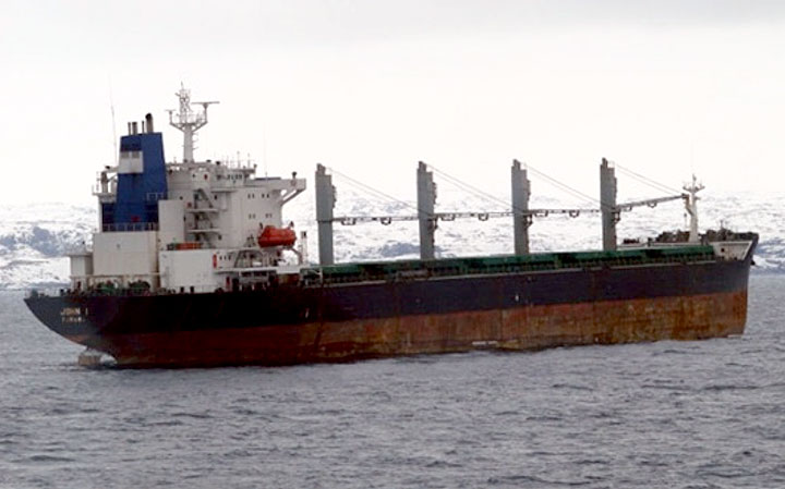
The John I is a bulk carrier built of steel with the engine room and accommodations located aft (Photo 1). The vessel has 5 double-bottom cargo holds that are serviced by 4 electric-hydraulic cranes. The bridge is fitted with navigational equipment including 2 automatic radar plotting aids, an echo sounder, and an automatic identification system. The vessel also has a simplified voyage data recorder.
History of the voyage
On 03 March 2014, the John I departed Las Palmas de Gran Canaria, Spain, headed for Montréal, Quebec, to load grain. While en route, the vessel received information from its Canadian shipping agent about entering Canadian waters. This information included a pre-arrival information report and a document entitled Mandatory Winter Navigation Information for Sea Water Cooling TypesFootnote 2 from Transport Canada (TC). This document contained, among other things, a marine safety checklist for operation in ice-infested waters and schematics of different types of cooling systems. It also specified the mandatory ice navigation publicationsFootnote 3 that vessels must carry while in Canadian waters.
On the Mandatory Winter Navigation Information for Sea Water Cooling Types document, the master was required to identify the type of sea water cooling system on board the vessel. The master initially indicated that the vessel had a type 2 sea water cooling system, but was advised by TC that a type 2 system is not adequate for navigation in ice-covered waters. The master then sent further details and a schematic of the vessel's cooling system to TC. After consulting the schematic, TC determined that the cooling system was of type 4 classification, which met the requirements for navigation in ice-covered waters.Footnote 4
On 07 March, TC authorized the vessel to enter Canadian waters and proceed to Montréal after the master agreed to familiarize the engineering crew with the operation of the cooling system and test the system prior to entering ice-covered waters. The chief engineer developed instructions for the operation of the cooling system, in the form of a checklist, and instructed the engine room officers to read and understand the checklist.
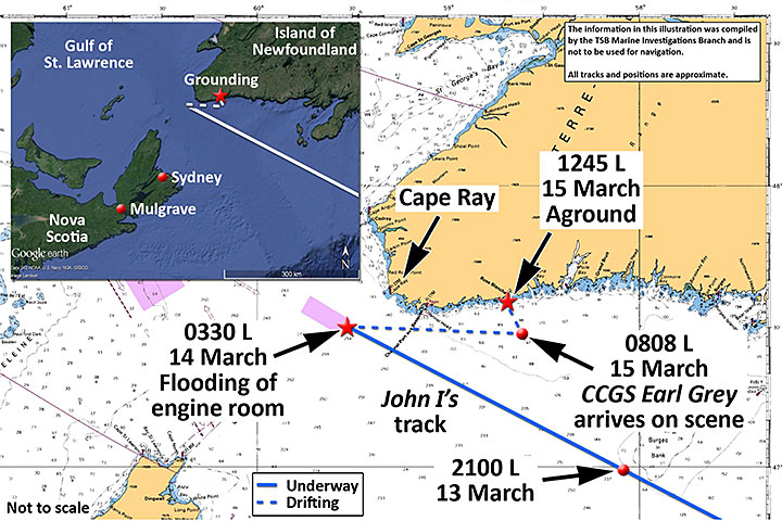
On 13 March, the vessel neared Saint-Pierre et Miquelon, France (located 14 nautical miles [nm] off the south coast of Newfoundland) where an ice advisorFootnote 5 was scheduled to embark on board late the next day. The master gave orders to slow and eventually stop propulsion, allowing the vessel to drift while awaiting the ice advisor's arrival in Saint-Pierre et Miquelon. After the vessel had been adrift for about 6 hours, the weather conditions worsened. The master consulted with the agent, and then made the decision to proceed to Les Escoumins, Quebec, without the ice advisor on board. To navigate, the master used 20 black and white photocopies (each photocopy was 21.59 cm x 27.94 cm) assembled from British Admiralty chart No. 4002 (Appendix A). The scale of the chart was 1:750 000. The investigation could not determine which edition of the chart was used. The compilation did not contain all the information necessary to navigate in proximity to the coastline in the Gulf of St. Lawrence.
In preparation for entering ice-covered waters, the chief engineer prepared an ice checklist, gave night orders to the crew, checked all of the valves for the cooling system, and opened the steam valve to the low sea chest.
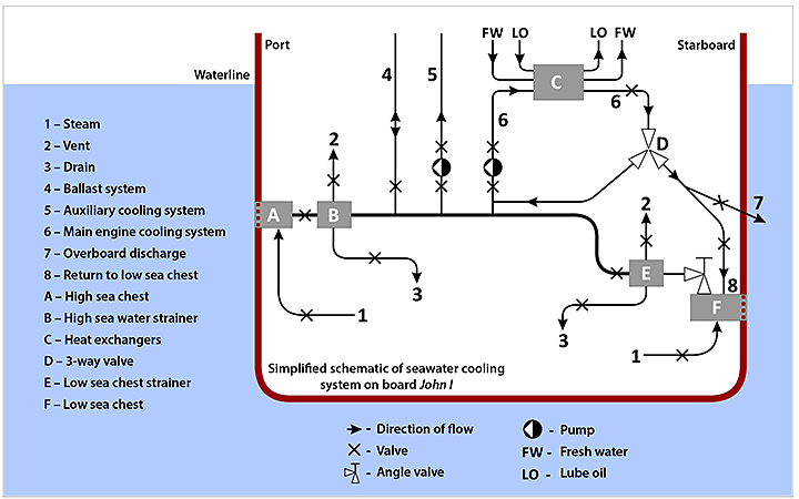
At approximately 2100,Footnote 6 the vessel entered ice-covered waters (Appendix B). The vessel's cooling system was drawing water via the low sea chestFootnote 7 at this time (Appendix C). At 2106, the master requested information from the Eastern Canada Vessel Traffic Services Zone (ECAREG) on the ice formation at the vessel's location at the time and, at 2116, received the relevant information, complete with 4 ice charts.
On 14 March, at approximately 0130, the third engineer standing watch noticed a rise in temperature in the fresh water cooling system. He called the chief engineer, who attributed the rise in temperature to a blockage in the low sea chest suction. The chief engineer closed the low sea chest valve and opened the high sea chest valve in order to lower the fresh water temperature; however, the flow of sea water through this line was also impeded.
After obtaining the master's consent to draw water from the forepeak ballast tank, the chief engineer set all the appropriate valves in the engine room accordingly (Appendix C). The master then went to the ballast control room, where he opened the necessary valves to allow water to begin circulating within the sea water cooling system, which in turn lowered the fresh water temperature. Suspecting a build-up of ice, the chief engineer unbolted the cover of the housing containing the low sea water strainer.Footnote 8 The second engineer arrived in the engine room and began assisting the crew to clear the ice and slush from the now-exposed sea water strainer.
At approximately 0320, as the crew were clearing the ice and slush, they noticed water beginning to overflow from the sea water strainer housing. The second engineer went to the low sea chest valve, where he attempted to tighten the valve by hand. Not being able to move the hand wheel, he then attempted to tighten it using an F-key,Footnote 9 at which time the valve operating mechanism failed. The hydrostatic pressure on the valve discFootnote 10 pushed the unsecured valve operating mechanism upwards, allowing sea water to enter the uncovered sea water strainer housing in an uncontrolled manner and overflow into the engine room.
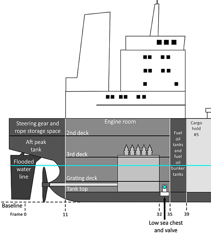
The chief engineer immediately informed the master of the situation, and the master joined him in the engine room. The chief engineer, along with the engine room crew, made multiple attempts to secure the cover on the sea water strainer housing. However, due to the rate of water ingress, these attempts were unsuccessful. Within approximately 10 minutes, the water in the engine room was approximately 4 metres deep and had reached the level of the grating deck, from which the crew were still attempting to secure the cover on the sea water strainer housing (Appendix D). Upon seeing electrical sparks, the master ordered that the vessel be blacked out and the engine room evacuated.
At approximately 0350, the crew were mustered on the upper deck and briefed on the situation. The emergency generator was started, and put on line. The chief mate prepared the crew and the vessel for possible abandonment. The master ordered the water level in the engine room to be monitored and the adjacent compartments to be checked for water ingress. At around 0410, the master informed the managing company of the situation. The company began making arrangements to secure a tug to assist the vessel. The company also began making arrangements for contractors to assist with restoring electrical power and preparing the vessel for towing.
At approximately 0556, the master advised Port aux Basques Marine Communications and Traffic Services (MCTS) of the situation. MCTS in turn relayed the details to the Joint Rescue Coordination Centre (JRCC) in Halifax, Nova Scotia, and added that a commercial tug was being arranged to assist the vessel. MCTS also notified TC and the Canadian Coast Guard's (CCG) Environmental Response (ER). JRCC requested that the vessel provide updates every 2 hours. At this time, the vessel was approximately 9 nm off Cape Ray, Newfoundland and Labrador (Appendix B), and the winds were northwesterly at 20 knots. The vessel was drifting easterly, parallel to the coast.
By 1130, the company had contracted the tug Ryan Leet to assist the vessel, and preparations for its departure were underway. The tug, which was in warm lay-up with a reduced crew, was scheduled to depart from the Mulgrave Marine Terminal in Nova Scotia at 0030 the following day.
At 2009, JRCC became aware of a forecasted increase in winds for the following day, which could cause the vessel to drift towards the island of Newfoundland. In addition, JRCC determined that if the John I began drifting towards the shore, the Ryan Leet, which had not yet departed, would not arrive in time to prevent the vessel from grounding. At 2100, the vessel reported to MCTS that it was drifting easterly at approximately 1.5 knots. One hour later, JRCC tasked the Canadian Coast Guard Ship (CCGS) Earl Grey, which was docked in Sydney, Nova Scotia, to assist the John I. The CCGS Earl Grey departed 30 minutes later.
On 15 March at 0355, the Ryan Leet left Mulgrave with an estimated time of arrival on scene of 1800. However, while en route, the tug encountered poor weather and ice conditions that caused it to push its estimated time of arrival back 3 times, with a final estimate given of 0600 on 16 March.
At 0700, the winds were at 2 knots from the south, and the John I was drifting northwesterly at 0.5 knots towards the Rose Blanche Shoals, which were approximately 7 nm away.
The CCGS Earl Grey arrived on scene at approximately 0800 and maintained a position approximately 1 nm from the vessel. At 1010, the CCGS Earl Grey informed the John I that the vessel could go aground within the next 3 to 4 hours and stated that the Ryan Leet would not arrive in time to provide assistance. The CCGS Earl Grey also informed the master that there were shoals off Rose Blanche and offered to tow the vessel further from the shoreline. The master informed the CCGS Earl Grey that the shoals were not indicated on his chart. He requested the current depth of water under the vessel, as his depth sounder was not functional at the time.
At 1054, the master informed the CCGS Earl Grey that he had advised the company of the situation and the company was attempting to have the tug arrive earlier. The master then stated that he was considering the option of going to anchor. The CCGS Earl Grey advised the John I of the forecasted 40- to 45-knot southeasterly winds later that day and communicated that they had light towing gear that could be used to establish a tow in good weather only. The master replied that he would relay this information to the company.
At 1112, JRCC contacted the master of the John I and advised that there was no time left to consult with the company, given the forecast of increasing southeasterly winds. JRCC also advised that anchoring should be considered a last resort. The master replied that he would get back to them in 10 minutes. He then asked the agent to inquire about the costs associated with accepting towing by the CCG.
At 1137, the CCGS Earl Grey informed the master that the John I was approximately 2 nm from the shoal. Three minutes later, the master asked the CCG about the costs of accepting a tow, to which the CCG replied there were none. The master then accepted to be towed.
A short time later, as the towline was being hauled up by the crew on the John I, part of it slipped back into the water, where it was cut by one of the propellers of the CCGS Earl Grey. The CCGS Earl Grey's fast rescue craft was then launched and its crew attempted to shackle together the towline with mooring lines lowered from the John I. During this attempt, both vessels kept drifting towards the shoals. When the depth sounder on the CCGS Earl Grey indicated less than 40 metres of water, the master of the CCGS Earl Grey aborted the attempt,Footnote 11 advising the master of the John I that he should drop the anchors.
The vessel let go its starboard anchor at approximately 1233, followed 5 minutes later by the port anchor. However, the vessel continued to drift with the wind, running aground on the Rose Blanche Shoals at approximately 1245, in position 47°35.30΄ N, 058°42.64΄ W (Appendix B). Subsequently, the crew were evacuated by a search and rescue (SAR) helicopter.
At 1610 on 15 March, as no further SAR actions were required, JRCC handed over the case to CCG ER.
The CCGS George R. Pearkes arrived on scene at approximately 2200 to relieve the CCGS Earl Grey and monitor the John I's movement, as the wind and tide had freed the vessel from the shoals. While the John I was dragging its anchors, it severed a fibre optic cable owned by a Nova Scotia high-speed internet provider.
On 16 March, the tug Ryan Leet arrived on scene at 0616, followed the next day by the contractors who had been hired to prepare the vessel for towing. By 20 March at 0820, the tug Atlantic Fir had arrived, and the 2 tugs began towing the John I towards Argentia, Newfoundland and Labrador, arriving on 22 March at 1845.
It was reported that no pollutants were released.
Damage to the vessel
The hull sustained tears, punctures, and dents. The damage was mainly concentrated on the port side of the vessel, approximately from midships to frame 32, which is located 5.6 metres aft of the engine room forward bulkhead (Appendix D). The engine room machinery and electrical components located below the flooded waterlineFootnote 12 were rendered inoperable.
Personnel certification and experience
The crew of the John I were all certified for their positions on board. Their certificates were issued by the Egyptian Authority for Maritime Safety and were compliant with the Standards of Training, Certification and Watchkeeping.Footnote 13
The master held a Master's certificate with no limitations, issued in February 2013. He had been sailing since 2002, and had joined both the company and the vessel 9 months prior to the occurrence. The master had previous experience navigating in ice-covered waters on the Azov Sea and the Black Sea.
The chief engineer held a Marine Chief Engineer certificate with no limitations, issued on 03 February 2010. He had been sailing since 1997, and began working for this company in 2005. He had 4 years of experience as a chief engineer, and had joined the vessel 6 months prior to the occurrence.
The second engineer held a Second Marine Engineer certificate with no limitations, issued on 14 November 2012. He had been sailing since 2001, and had worked for this company since 2006. He had 2 years of experience as a second engineer, and had joined the vessel 6 months prior to the occurrence.
The occurrence voyage was the master and chief engineer's first voyage into ice-covered waters in Canada.
Vessel certification
The John I was certified and equipped in accordance with existing regulations. The vessel had undergone a classification society survey on 28 July 2010, at which time it was recommended that the vessel be retained within Class. The vessel had a safety management system (SMS), and the company held a document of compliance that was valid until 14 December 2016. The vessel held a safety management certificate that was issued on 14 October 2013 and was valid until 02 October 2018.
Environmental information
At the time of the flooding, at approximately 0330 on 14 March, the skies were overcast and the temperature was just below freezing. The vessel also reported that the water was covered in ice to an extent of nearly 100% and that the prevailing winds were southwesterly at a force of 7 on the Beaufort scale. Following the flooding, the winds were primarily northwesterly, and the vessel was drifting east.
The Rose Blanche Shoals, 0.5 to 1 nm southwest of Rose Blanche Point, comprise numerous sunken rocks located 4 to 6 metres below the surface. Approaching the shoals from the south, the sea bed rises rapidly (the water depth decreases from 100 metres to less than 40 metres over a distance of approximately 500 metres).
Navigating in ice-covered waters
The CCG issues a publication entitled Ice Navigation in Canadian Waters,Footnote 14 which is intended to assist vessels operating in ice in Canadian waters. The publication provides information about regulations, shipping support services, hazards, and navigation techniques in ice. Among other things, the publication states that the propulsion plant and steering gear of the vessel must be capable of a fast and reliable response to manoeuvring orders. It also notes that engine room suction strainers should be easily removed and kept clear of ice and slush.
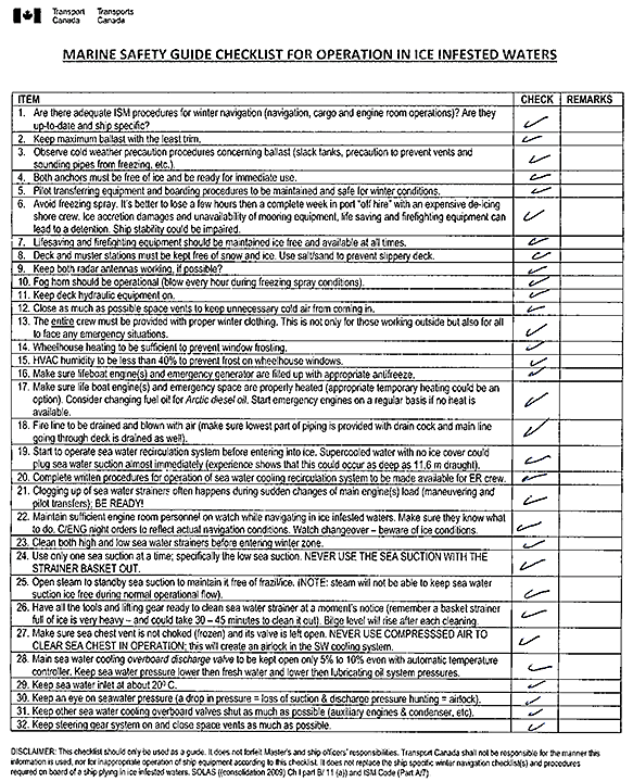
TC issues a publication entitled Mandatory Winter Navigation Information on Sea Water Cooling Types to all incoming vessels informing them of domestic regulations with respect to operating in ice-covered waters. These regulations require vessels to be equipped with a system that prevents icing and blockages in the sea chest to ensure a supply of cooling water is maintained. The publication also contains a checklist entitled “Marine Safety Guide Checklist for Operation in Ice Infested Waters” (Appendix E) that covers 32 items, among which are the following:
- the sea water inlet should be kept at 20°C, and
- the main sea water overboard discharge valve should be kept open only 5% to 10%.
Item 25 of the checklist specifies that steam and/or compressed air to the sea chest is not a defense against ice and slush build-up, given that steam and compressed air will not be able to keep the sea chest ice-free during normal operations.
The completion of the checklist from this publication and submission to TC was made compulsory for vessels transiting west of Les Escoumins, as of the winter navigation season of 2011-2012. Prior to entering Canadian waters, the master on the John I had received the Mandatory Winter Navigation Information on Sea Water Cooling Types document from TC, and had completed and returned the checklist for operating in ice-infested waters, as required. All boxes corresponding to checklist items had been checked (Appendix E).
Engine cooling system
Vessel engines operate at high temperatures and, as such, are fitted with cooling systems designed to protect the various engine parts from overheating. Overheating can cause degradation of the mechanical properties of engine parts that may lead to catastrophic failure.
The John I main engine uses lubricating oil to lubricate moving parts and chemically-treatedFootnote 15 fresh water pumped through internal passages in the engine to cool, among other things, the engine cylinders and heads. Heat from the engine parts is transferred to the lubricating oil and fresh water through the process of convection.Footnote 16 In order to dissipate heat before being recirculated through the engine, the fresh water and lubricating oil flow through heat exchangers,Footnote 17 where heat transfers to circulating sea water that is drawn in from either the low or the high sea chest, under normal operating conditions. The temperatures of the fresh water and lubricating oil cooling systems are controlled using valves that regulate the quantity of lubricating oil and fresh water flowing into the heat exchangers. These valves can be operated manually or automatically through a set of thermostatic controls.
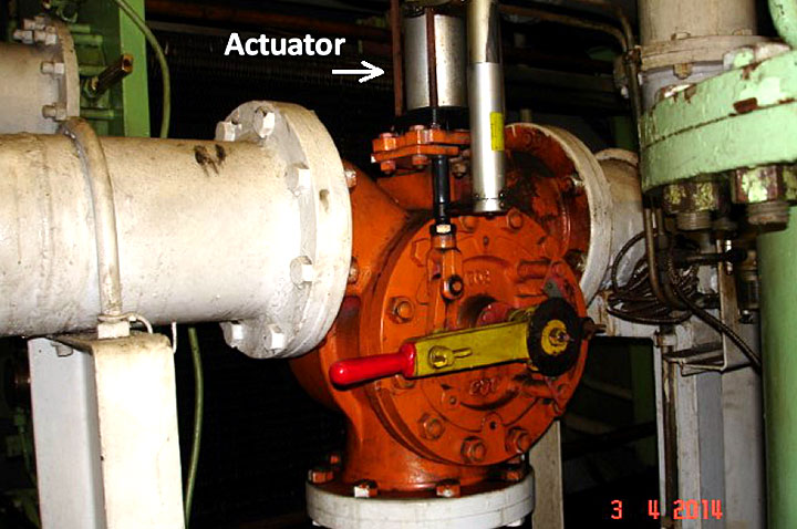
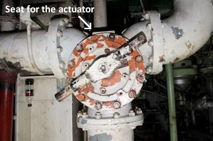
A post-occurrence examination of the John I determined that the vessel's sea water cooling system (Appendix C) was a type 4 system with an additional capability to recirculate warmed sea water to the heat exchanger via the sea water pump, a feature normally found in a type 2 system. As such, by adjusting the flow rate through the 3‑way valve (Photo 3) and subsequent valves, the warmed sea water leaving the various heat exchangers, could be
- returned directly to the main sea water pump suction, and/or
- discharged overboard, and/or
- sent to the low sea chest, where it would mix with the incoming sea water to help melt ice and slush.
The post-occurrence examination found that the 3‑way valve on the John I was set so that the warmed sea water leaving the various main engine heat exchangers was being partially discharged overboard and partially returned to the main sea water pump suction.
The examination also found that the valve that permitted sea water to recirculate to the low sea chest was closed.
The vessel's main and auxiliary sea water cooling system drawing indicates that the 3‑way valve was designed with thermostatic controls for automatic operation. With automatic operation, the thermostatic controls sense the temperature of the sea water entering the heat exchanger and then send signals to an actuator to adjust the 3-way valve in order to maintain a pre-set sea water temperature. Depending on the adjustment of the 3-way valve, the warmed sea water is automatically directed either back into the cooling system or to the sea chest/overboard discharge.
Although the seat for the actuator assembly on the 3‑way valve was still in place at the time of the occurrence and the valve was shown to be fitted with an actuator on the main and auxiliary sea water cooling system drawings, the actuator and its components had been removed (Photo 3). As such, the 3‑way valve could only be operated manually. The time at which the actuator had been removed is unknown.
Low sea chest valve operating mechanism
On the John I, the low sea chest angle valve is opened and closed via a gear mechanism. Rotation of a large gear moves the valve stem up and down through 2 collars that are threaded together to form a single unit.Footnote 18 The upper collar is made of brass and the lower is made of steel (Figure 1). The brass collar has internal threading for the valve stem, while the steel collar does not. The valve stem and collars are held in place by a bridge (secured to the valve body). The steel collar has a flange that holds the valve operating mechanism in place when an upward force is exerted on the valve disc.
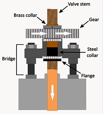
Post-occurrence, the brass and steel collars were found to have separated. Reassembly of the collars demonstrated that they did not fit together well.
The brass threads did not engage with the steel threads until the brass collar had been well inserted in the steel collar, and the threads on the bottom end of the brass collar were in poor condition; however, neither collar showed signs of thread stripping.Footnote 19
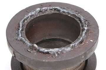
Thread locking compoundFootnote 20 residue was found on both collars; this compound was the only means of preventing disengagement of the collars. The underside of the flange on the steel collar was found to have a pre-existing weld (Photo 4).
Valve position indicators
The low and high sea chests within the sea water cooling system on the John I each have a valve that controls suction. These valves were each fitted with an extended drive shaft that could be operated using 3 hand wheels (1 located at the grating deck, 1 at the second deck, and 1 at the third deck in the engine room) (Appendix D). At each location, the extended drive shaft was fitted with a valve position indicator to indicate whether the valve was open, closed, or somewhere in between. If the sea chest valve discs were not fully closed to create a watertight seal, sea water could enter the cooling system by seeping in around the valve disc.
Each valve position indicator consisted of a fixed vertical plate marked at the top, open, and at the bottom, closed. The plate had a vertical slot, within which an indicator affixed to threads on the valve extended drive shaft would move up or down indicating the position of the valve disc as the extended drive shaft was turned (Figure 2). The post-occurrence inspection found that the vertical plate of the valve position indicator located at the grating deck was bowed outwards and its indicator was bent upwards and therefore no longer fitted within the slot in the fixed vertical plate (Photo 5).
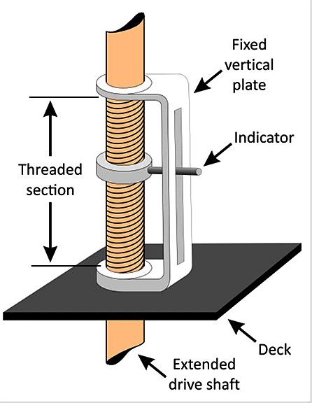
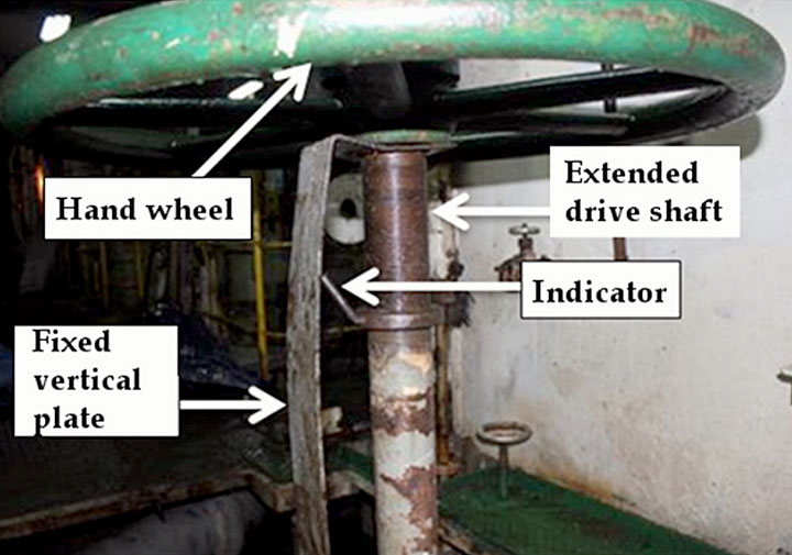
In this condition, the indicator could turn freely within the valve extended drive shaft and not be moved up or down by the effect of the threads on the shaft, preventing the indication of the position of the valve disc when in operation. The valve position indicators for the high and low sea chest valves at 5 other locations were found in various states of disrepair, rendering them unreliable (Photo 6 and Photo 7).


Safety management system
The objectives of the International Safety Management (ISM) CodeFootnote 21 adopted by the International Maritime Organization are to ensure safety at sea, prevent human injury or loss of life, and avoid damage to the environment. The ISM Code requires a company to document its management procedures and to define and document the master's responsibilities.
The company's SMS was dated 29 August 2011 and was approved by the managing director. Chapter 7 of the company's SMS manual referred to maintenance, and specified that the company had established a maintenance program and routine inspection program. The manual identified a list of critical equipment and systems that included the sea water main pumps within the cooling system.
Chapter 12 (12.2.18) dealt with cold weather precautions and indicated that the company had provided vessels with a checklist for routine precautions for operating in cold weather, snow, and ice. The checklist for the John I contained a number of precautionary measures. The only specific measure with respect to the sea water cooling system during ice navigation was the following: “Engine room has been continuously manned in case of ice blockage in the cooling systems.”
The John I also carried a Shipboard Contingency Manual for responding to emergency situations. This manual was approved by the managing company and dated 25 April 2013. The manual emphasized the following:
The ship master has the overriding authority and responsibility to take decisions with regards to safety of human life, property and the environment. Any requirement, instruction or guidance imposed by shore management must not detract him from either his authority or responsibility when dealing with safety or pollution prevention. He must not wait for approval to act.
Emergency towing in Canada
When a vessel becomes disabled in Canadian waters, it is the owner's responsibility to make arrangements with a private or commercial vessel for a tow. However, for disabled vessels where there is the potential for endangerment to lives or the environment, the CCG will evaluate the risks and provide towing assistance.
Emergency towing operations provided by the CCG are at no cost to the vessel owner. Before proceeding with emergency towing, the CCG requires that the vessel accept a standard towing agreement that outlines the risks of the operation and exempts the CCG, among other things, from responsibility for any damage caused to the vessel.Footnote 22
Powers of the emergency response authorities
Under the Canada Shipping Act, 2001 (CSA 2001), the Minister of Fisheries and Oceans, who is the minister responsible for the CCG, may take measures deemed necessary to “repair, remedy, minimize or prevent pollution damage from the vessel” where it is believed on reasonable grounds that a vessel is discharging or likely to discharge a pollutant.Footnote 23 This also includes, when it is considered necessary to do so, directing any person or vessel to take those measures or to refrain from doing so. The practice of the CCG is that these measures may be taken by the Environmental Response (ER) pollution response officer as the on-scene-commander for the incident.
As per the CSA 2001, pollution response officers also have the power to order a vessel to proceed to a designated place, by a route and in a manner specified, and to moor, anchor, or remain there for a specified period of time if the pollution response officer has reason to believe that the vessel might discharge a pollutant.Footnote 24
Rescue coordinators employed in JRCC coordinate the rescue effort, monitoring the development of the situation and, at times, making recommendations to the vessel in distress. Rescue coordinators from JRCC are empowered under the CSA 2001, and, as such, have the power to “give any directions that the rescue coordinator considers necessary to carry out search and rescue operations for that person, vessel or aircraft.”Footnote 25 This provides a coordinator with the authority to direct a vessel to provide assistance as part of the SAR response, but not to direct a vessel in distress to accept assistance, such as the taking of a tow.
Pursuant to the CSA 2001, TC inspectors, on behalf of the Minister of Transport, also have powers to direct a vessel where it is believed on reasonable grounds that the vessel will discharge or has discharged a pollutant. This includes directing a vessel to proceed to a selected place by a specified route and manner.Footnote 26
In this occurrence, JRCC, CCG ER, and TC had been alerted to the situation with the John I. It was designated as a SAR operation. According to CCG policy, environmental response is not initiated until SAR is completed, in other words, when “the persons aboard the disabled vessel have been transferred to a safe place.”Footnote 27 The CCGS Earl Grey, which was on scene, was responding as part of the SAR operation. None of the crew on board held the powers of a pollution response officer, nor were CCG ER pollution response officers or TC pollution prevention officers requested to intervene.
Reported sea water suction incidents
When vessels experience sea water suction problems, those occurrences are not required to be reported under the Canadian Transportation Accident Investigation and Safety Board Act (CTAISB). However, those facts may be reported voluntarily to the TSB. Information contained in the TSB database indicates that from 2003 to 2013, a total of 251 such incidents were reported. During that period, the highest number of reports for a single calendar year was 35 (in 2009), and the lowest was 11 (in 2013).
TSB laboratory reports
The following TSB laboratory report was completed in support of this investigation:
- LP 100/14 – Valve Examination
Analysis
Events leading to the flooding and grounding
Flooding
When the John I entered ice-covered waters, the sea water cooling system was not set to recirculate warmed sea water into the low sea chest, where it would have melted ice and slush. The sea water strainer became plugged, which prevented the circulation of sea water from the low sea chest to the various main engine heat exchangers.
In order to draw sea water from the forepeak ballast tank to cool the main and auxiliary engines, the crew attempted to close the low sea chest valve; however, the valve disc was prevented from fully closing. This was likely due to ice blocking the valve operating mechanism or because the valve disc did not form a watertight seal with the seat for other reasons (e.g., wear and tear, misalignment). The crew were not aware that the valve disc had not fully closed, nor did they have the visual means to verify that the valve disc had reached its closed position.
When the cover of the housing containing the sea water strainer was opened to clear the strainer of ice, the pressure differential forced water past the partially open valve. The water filled the sea water strainer housing and began overflowing into the engine room. The attempt to further tighten the low sea chest valve using the F-key overstressed the valve operating mechanism and caused the poorly fitting brass and steel collars around the valve stem to separate. Once the collars separated, the sea water pressure pushed the valve operating mechanism (including the valve disc, stem, brass collar and associated gear) upwards, which allowed more water to flow into the engine room and flood it until it reached a level of equilibrium with outside sea pressure. The master then ordered a blackout, and the vessel began drifting.
Grounding
As the John I drifted, the master was plotting the vessel's position; however, the on-board small-scale photocopied chart provided little detail of the hazards along the shoreline. With no other navigational information, the master was unaware of the steep rise of the sea bed and the presence of shoals along the coastline where the vessel was drifting.
After the arrival of the Canadian Coast Guard Ship (CCGS) Earl Grey, the master on the John I was advised of the shoals and offered a tow. However, the master, concerned whether there would be costs or a claim for salvage associated with the tow, conferred back and forth with the company about the next course of action, which limited the time to act.
The master had the option to anchor the vessel, but did not appreciate the difficulty of anchoring in that area under the environmental conditions at that time, as well as the limitations of the assistance that could be provided by the CCGS Earl Grey.
The CCGS Earl Grey and the Joint Rescue Coordination Centre (JRCC), knowing that the Ryan Leet was delayed and that the winds were pushing the John I towards shore, continued to impress upon the master the urgency of the situation. Neither Transport Canada (TC) nor the Canadian Coast Guard's (CCG) Environmental Response (ER), both of which had the power to direct the vessel to take action including accepting the offer to tow, were requested to intervene in the developing situation.
By the time the master accepted the tow and an unsuccessful attempt was made, the proximity of the vessel to the shoals and the steep rise of the sea bed prevented the completion of a second towing attempt. Although the John I deployed its anchors, it was unable to stay off of the shoal and went aground.
Preparing for navigation in ice-covered waters
Special precautions must be taken when a vessel is navigating in ice-covered waters, particularly when it comes to main and auxiliary sea water engine cooling systems. Without adequate defenses, the build-up of ice and slush in the sea water cooling system can occur quickly and cause the engine to overheat and shut down. As such, the crew must be aware of the dangers that cold water, ice, and slush pose with respect to the sea water cooling system and must adjust its operations accordingly.
During this voyage, there were indications that the crew were not adequately familiarized with the cooling system, nor had they properly prepared the cooling system for operating in ice-covered waters:
- The crew inaccurately identified the type of sea water cooling system on board the vessel when initially required to provide this information to TC;
- The warmed sea water leaving the various main engine heat exchangers was not being recirculated to the low sea chest to melt ice; and
- The steam valve to the low sea chest had been opened to prevent the build-up of ice and slush, despite the indication in documentation from TC that this is ineffective
Although the master had indicated that all of the precautions for navigating in ice-covered waters included on TC's checklist had been taken, some important measures to protect the cooling system were not in place. Furthermore, while the chief engineer had created an on-board checklist for the operation of the sea water cooling system, a copy of the checklist could not be obtained and, therefore, it could not be determined whether the checklist was sufficient to prevent the build-up of ice. The 3-way valve was found to be discharging the warmed sea water overboard, suggesting that the crew did not follow the checklist, the checklist did not cover all the precautions necessary, or the checklist gave erroneous instructions.
In this occurrence, without an adequate defense (warmed sea water), slush and ice built up in the sea water strainer during the 4 hours after the vessel began navigating in ice-covered waters. If the crew are not familiar with the measures necessary to prepare and operate a vessel's sea water cooling system when navigating in ice, there is a risk that the main and auxiliary engines will overheat, leading to a loss of propulsion and/or a vessel's electrical power.
Management of emergency response
In the event of an emergency where there is a threat to the safety of lives, property, or the environment, it is essential that the appropriate authorities make timely decisions and work in a coordinated fashion to manage situations. If response measures are not coordinated between authorities, crucial actions may be delayed which may result in more severe consequences.
In an emergency, the master is in the best position to judge the vessel's condition, the weather, and other factors on which to base the decisions. In fact, the John I's Shipboard Contingency Manual stipulates that the master has the overriding authority and responsibility to take decisions with regards to safety of human life, property and the environment. However, if action is not being taken in a timely manner, national authorities which are vested with the necessary powers to guard against loss of life and prevent or minimize property damage, must intervene. CCG ER pollution response officers, on behalf of the Minister of Fisheries and Oceans, may, on reasonable grounds that a vessel is likely to discharge a pollutant, “take the measures that he or she considers necessary to repair, remedy, minimize or prevent pollution damage from the vessel.”
In this occurrence, though the CCGS Earl Grey and JRCC repeatedly communicated the importance of initiating the tow and the urgency of the situation to the John I, TC and CCG ER, the authorities with legislative powers to direct a vessel to take action, were not requested to intervene, and therefore did not exercise these powers. During the time that JRCC was attempting to convince the master to accept the tow, a SAR mission was underway and, as per the practice, the transfer of responsibility to TC or CCG ER does not occur until the SAR mission is deemed to be completed.
The delay in starting the towing operation in this occurrence was a contributing factor to the grounding. The delay was caused both by the reluctance of the master to accept the offer to tow and by the way that the authorities managed the situation.
JRCC was responding to the SAR and did not have the authority to direct the master of the John I to accept the tow. CCG ER and TC, both of which had the authority to direct the vessel, were not actively involved at an earlier stage when it was clear that the time to take action was running out and the environmental risks posed by the vessel going aground were increasing. If all authorities responsible for dealing with an emergency are not involved in a timely and coordinated manner, there is a risk that response options will be limited and the situation will escalate.
Findings
Findings as to causes and contributing factors
- Warmed sea water from the heat exchanger was being both discharged overboard and returned to the pump rather than being recirculated into the low sea chest; as such, the sea water strainer became plugged with ice and slush, causing the vessel to lose sea water suction from the low sea chest.
- When the crew attempted to close the low sea chest valve, the valve disc was prevented from fully closing likely due to ice caught between the valve disc and its seat or because the valve disc did not form a watertight seal with the seat.
- Without a working indicator, the crew had no visual means to confirm that the low sea chest valve was fully closed.
- The brass and steel collars around the valve stem, which were poorly fitted, separated when the low sea chest valve operating mechanism was overstressed while being tightened.
- The pressure of the sea water pushed the valve operating mechanism upwards, increasing the rate at which water entered the open sea water strainer housing and flooded the engine room.
- With the engine room flooding, the master ordered a blackout, and the vessel began drifting.
- The master of the John I did not accept the initial offers to tow made by the Canadian Coast Guard Ship Earl Grey, but instead conferred back and forth with the Canadian Coast Guard and the company about the next course of action to take, thereby delaying the attempt to establish a tow.
- Once the master accepted the tow, the Canadian Coast Guard Ship Earl Grey'sfirst attempt to establish a towline on the John I failed; by this time the vessel's proximity to the shoal did not allow for completion of the second attempt and, although the John I let go both anchors, the vessel ran aground on the shoal.
Findings as to risk
- If crew are not familiar with the measures necessary to prepare and operate a vessel's sea water cooling system when navigating in ice, there is a risk that the main engine will overheat, leading to a loss of propulsion.
- If all authorities responsible for dealing with an emergency are not involved in a timely and coordinated manner, there is a risk that response options will be limited and the situation will escalate.
This report concludes the Transportation Safety Board's investigation into this occurrence. The Board authorized the release of this report on . It was officially released on .
Appendices
Appendix A – Photograph of the chart carried on board the John I

Appendix B – Area of the occurrence
Appendix C – Vessel's cooling system
Appendix D – John I profile up to frame 39
Note: “Flooded waterline” indicates the level of water ingress in the engine room after the flooding.