Derailment
Canadian National Railway
Freight train M37231-05
Mile 144.4, St-Laurent Subdivision
Taschereau Yard, Montréal, Quebec
The Transportation Safety Board of Canada (TSB) investigated this occurrence for the purpose of advancing transportation safety. It is not the function of the Board to assign fault or determine civil or criminal liability. This report is not created for use in the context of legal, disciplinary or other proceedings. See Ownership and use of content. Masculine pronouns and position titles may be used to signify all genders to comply with the Canadian Transportation Accident Investigation and Safety Board Act (S.C. 1989, c. 3).
Summary
On 06 November 2013, at approximately 0505 Eastern Standard Time, Canadian National freight train M37231-05 derailed 10 empty cars while travelling through a tight curve at Taschereau Yard in Montréal, Quebec. The derailed cars and the track were damaged. There were no injuries.
Factual information
The accident
On 05 November 2013, at about 2130,Footnote 1 eastbound Canadian National (CN) freight train M37231‑05 (the train) departed Belleville, Ontario, en route to CN's Taschereau Yard in Montréal, Quebec (Figure 1). The train consisted of 2 locomotives and 72 cars. It weighed approximately 7000 tons and was about 5300 feet in length. The operating crew consisted of a locomotive engineer (LE) and a conductor. Both crew members were qualified for their respective positions and met the regulatory rest and fitness requirements.

At approximately 0350 on 06 November 2013, following an 11-car setoff in Coteau, Quebec, the train resumed its journey with 61 cars marshalled behind the locomotives as follows:
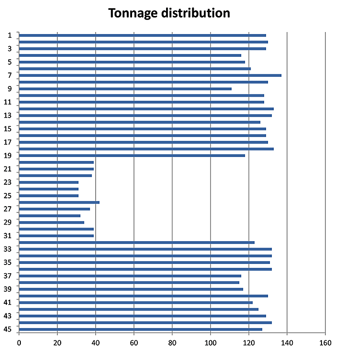
- The 1st to 19th cars were loaded, each exceeding 110 tons.
- The 20th to 31st cars were empty. This block included 7 box cars and five 80-foot-long centrebeam bulkhead flat cars, each equipped with long travel hydraulic end-of-car cushioning devices (EOCCDs).
- The 32nd to 45th cars were loaded, each exceeding 110 tons.
- The 46th to 61st cars were loaded multi-level autorack cars, each equipped with EOCCDs.
By 0440, the train had reached Taschereau Yard and the yardmaster's instructions were to proceed to the car compound.Footnote 2 The 16 cars on the tail end of the train were to be set off on track MC96 while the remaining 45 cars were to be moved to a different track.
Near the north end of track MC96, the conductor detrained and positioned himself to uncouple the trailing 16 autorack cars. The train then pulled ahead onto track CX01 and proceeded towards the receiving yard.
Upon reaching crossover switch XA52, the LE stopped the train, exited the cab and lined the crossover switch for track CX02. The LE then returned to the locomotive cab, moved the train forward onto track CX02 and stopped with the train occupying tracks CX02, CX01 and MC96 (Figure 2).

At approximately 0505, the conductor made the separation and left the tail-end 16 autorack cars on track MC96. The conductor then instructed the LE to pull ahead. The LE increased the locomotive throttle, relying on visual cues to determine the train's rate of acceleration. The locomotives moved approximately 50 feet when a train-initiated emergency brake application occurred and the train came to a stop. Subsequently, the crew determined that the 20th to the 29th cars had derailed in the body of the curve of track CX01.
At the time of the accident, the temperature was 5°C, the sky was overcast and wind speed was about 6 km/h.
Site examination
The site examination revealed the following:
- The 20th car from the locomotives (empty box car) had derailed, but remained coupled to the front of the train. This car was leaning at a 45° angle and was obstructing a crossing leading to the north exit of the yard (Photo 1).

- The following 9 empty cars (the 21st to the 29th cars) had derailed and were laying on their side. The 24th to the 29th cars were in the ditch adjacent to track CX01.
- The 29th car, an empty, 80-foot centrebeam bulkhead flat car equipped with EOCCDs, had separated from the rear portion of the train.
- The derailed cars were damaged and most of them had separated from their trucks. The knuckles and drawbars did not show any signs of distortion or rotation.
- The components of the derailed cars had been in good condition prior to the accident.
- The switch stand of crossover switch XA52 was destroyed by the 25th car.
- There were multiple wheel flange marks across the top of the inner rail. The field side of the corresponding supporting ties exhibited wheel impact damage.
- The trucks of the 29th car were located about 23 feet ahead of the markings on the top of the rail. The ballast between the two had been heavily displaced in the direction of train travel.
- The trucks of the 20th car had been dragged laterally for about 3 feet in the ballast.
Recorded information
Data from the locomotive event recorder (LER) of the lead locomotive are summarized in tables 1 and 2.
| Action | Time | Distance (feet) | Speed (mph) | Throttle | Tractive effort | Brake cylinder (psi) | Brake pipe (psi) | End of train (psi) |
|---|---|---|---|---|---|---|---|---|
| Train is stopped. | 0459:37 | 1814 | 0 | Idle | 0 | 72 | 89 | 88 |
| Throttle is advanced. | 0501:59 | 1814 | 0 | T1 | 0 | 66 | 89 | 88 |
| Throttle is advanced. | 0502:00 | 1814 | 0 | T2 | 0 | 44 | 89 | 88 |
| Throttle is advanced. | 0502:11 | 1808 | <1 | T3 | 42 | 0 | 89 | 88 |
| Throttle is advanced. | 0502:33 | 1732 | 3 | T4 | 76 | 0 | 89 | 88 |
| Action | Time | Distance (feet) | Speed (mph) | Throttle | Tractive effort | Brake cylinder (psi) | Brake pipe (psi) | End of train (psi) |
|---|---|---|---|---|---|---|---|---|
| Train brakes are applied. | 0504:17 | 401 | 10 | Idle | 0 | 0 | 82 | 83 |
| Locomotive brakes are partially applied. | 0504:27 | 270 | 8 | Idle | 0 | 15 | 83 | 83 |
| Locomotive brakes are fully applied. | 0504:46 | 100 | 4 | Idle | 0 | 71 | 75 | 81 |
| Train brakes are released. | 0504:55 | 69 | 0 | Idle | 0 | 72 | 76 | 79 |
| Throttle is advanced. | 0505:05 | 69 | 0 | T1 | 0 | 71 | 88 | 77 |
| Throttle is advanced. | 0505:06 | 69 | 0 | T3 | 0 | 57 | 88 | 77 |
| Throttle is advanced. | 0505:11 | 67 | <1 | T4 | 38 | 5 | 88 | 77 |
| Throttle is advanced. | 0505:18 | 54 | 2 | T5 | 49 | 0 | 88 | 77 |
| Throttle is reduced. | 0505:24 | 27 | 2 | T4 | 88 | 0 | 88 | 77 |
| Throttle is reduced | 0505:30 | 1 | 1 | T1 | 0 | 10 | 0 | 0 |
| Throttle is closed. | 0505:31 | 0 | 0 | Idle | 0 | 26 | 0 | 0 |
Train M37231
Train M37231 operated daily from MacMillan Yard in Toronto, Ontario, to Taschereau Yard. This train normally carried mixed freight, including autorack cars. It was marshalled using destination blocking.Footnote 3 Upon arrival at Taschereau Yard, the train would normally proceed to the car compound, where the autorack cars were set off. The remaining cars would then be moved and set off at another location in the yard.
On the morning of the occurrence, the train departed Belleville with 72 cars, and 11 cars were set off at Coteau. It then proceeded to Taschereau Yard with 61 cars, including a block of 12 empty cars, all equipped with EOCCDs, which were marshalled together in position 20 to position 31 behind the locomotives. Of these cars, the 23rd to 25th cars and the 28th and 29th cars were 80-foot-long centrebeam bulkhead flat cars (Appendix A and Appendix B).
Taschereau Yard
Taschereau Yard, located at Mile 144.4 of CN's St-Laurent Subdivision, is CN's major yard in the Montréal area. This yard integrates switching and marshalling of freight trains, intermodal operations, repair shops, a car compound and transloading facilities for bulk commodities.
Taschereau Yard is configured as follows:
- The tracks are primarily oriented in the north-south direction.
- The yard contains approximately 110 miles of track and is equipped with about 460 switches.
- The yard has a maximum capacity of 4000 cars.
- About 25 trains arrive and depart daily, transporting approximately 190 000 cars per year.
- Train movements within the yard are governed by Rule 105Footnote 4 of the Canadian Rail Operating Rules (CROR) and are limited to a maximum speed of 15 mph.
Track information
Track CX01 is U-shaped and includes a tight 15.75° curve (Figure 2). There are 5 other tracks (CX02 to CX06) that have similar configurations and are located adjacent and parallel to track CX01 for part of the curve. Track CX01 links the car compound tracks with the receiving yard tracks, and was used daily by train M37231 when setting off autorack cars. Other yard movements and road switcher movements also use track CX01, resulting in annual rail traffic of about 2 million gross tons on this track.
At the time of the occurrence, track CX01 was in good condition. The track consisted of 136-pound continuous welded rail laid on 14-inch double-shouldered tie plates with 3 spikes per plate. The rail was box-anchored every 3 ties. The ballast consisted mainly of ½-inch to 2-inch crushed rock.
Crew information
The LE had 29 years of experience in the railway industry and had been working as an LE for the last 9 years. During the past year, the LE had been operating trains between Belleville and Taschereau Yard. He would regularly set off cars in the car compound and was familiar with the curvature of track CX01. The conductor had 3 years of operating experience and was familiar with Taschereau Yard.
The day before the occurrence, on 05 November 2013 at 0218, the crew members had been called in their assigned time windowFootnote 5 to operate a train from Montréal to Belleville. They arrived in Belleville and reported off-duty at 1252. They were transported to a Belleville hotel for rest. Approximately 7 hours later (at about 2000), they were called to operate train M37231-05 back to Montréal.
In-train forces
Train slack is the amount of movement that occurs within the train as cushioning devices are compressed (buff) or extended (draft) as in-train forces are transmitted between cars. Through the gradual application of the locomotive tractive effort, the train starts moving forward one car at a time as the slack is pulled taut. Depending on the type of car and the cushioning device, the amount of slack can vary:
- For cars equipped with standard cushioning devices (draft gears), the slack is approximately 6 inches per car.
- For cars equipped with EOCCDs, the slack can be as much as 36 inches per car.
EOCCDs are designed to dampen in-train force and minimize damage to lading. However, the presence of EOCCDs on a train can significantly increase the train's total slack.
When there are blocks of cars equipped with such cushioning devices on a train, the LE must be increasingly vigilant. If care is not taken, a sudden run-in or run-out of the train's slack can result in a train pull-apart or derailment.
In this occurrence, after the autorack cars were uncoupled from the train, the train had approximately 50 feet of slack (i.e., the cushioning devices had been compressed from using the locomotive independent brake to stop the train). Consequently, when the train began to move forward, the locomotives had to move ahead about 35 feet before the 29th car could begin to move (Appendix A).
Train marshalling and handling
The Association of American Railroads (AAR) Train Make-Up Manual indicates that cars equipped with EOCCDs will add to train slack and can greatly increase in-train forces. In general, blocks of empty cars equipped with EOCCDs should not be placed ahead of large blocks of loaded cars with conventional draft gears.
In-train forces, if left unchecked, have the potential to attain levels that can lead to broken knuckles, broken couplers, damage to lading, and derailments. Railways have developed specific train handling instructions to ensure the safe operation of the train. At CN, the Locomotive Engineer Operating Manual, Form 8960, specifies in part:
G1.1 Principles
SAFETY is the most important train handling principle. Safety is maximized when in-train and track-train forces are minimized.
[…]
G1.2 Policy
[…] To operate trains according to CN principles of safety, service and asset utilization, locomotive engineers must apply their knowledge, skill and professional judgment during the course of their duties.
[…]
G2.3 Use of Throttle
Use the throttle in a manner that provides gradual slack adjustment while minimizing in-train forces.
Make throttle changes one notch at a time.
When starting the train, do not move throttle to a higher position until amperage or tractive effort indicator remains steady or decreases.
[…]
Regulate tractive effort in high curvature territory to reduce the possibility of ‘string-lining', which can occur when excessive lateral forces are created.
To regulate tractive effort, LEs are required to monitor the gauge on the locomotive control stand that displays tractive effort and to moderate their train handling accordingly.
Lateral and vertical forces
A combination of lateral (L) and vertical (V) forces exists at the wheel-rail interface (Figure 3). The ratio of lateral-to-vertical (L/V) force indicates the likelihood of a derailment. When a high lateral force and low vertical force is present (e.g., as with an empty car), the high lateral force will tend to push the wheel flange up and over the gauge face of the rail, resulting in a wheel-climb derailment.
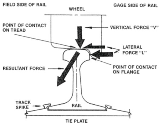
When a train is being pulled through a curve, the locomotives tend to stretch or “string-line” the train, which pulls the wheel flanges against the inside rail of the curve. This lateral force at the rail varies directly with the locomotive applied effort, track grade and degree of curvature. If the draft force generated by the locomotives is excessive or if there is a significant run-out of train slack, the L/V force can reach critical levels where car wheels climb or overturn the inside rail. Empty long centrebeam bulkhead flat cars are particularly susceptible to these forces.
String-lining derailments are caused by heavy draft loading, including steady-state draft loading or (more often) dynamic run-outs of slack. String-lining derailments exhibit the following characteristics:Footnote 6
- String-lining derailments happen in curves, not in tangent track.
- String-lining is often associated with excessive application of power in forward movements, and often involves the head-end cars of a train derailing after the train accelerates from a low speed in high curvature territory (classic scenario).
- Derailed cars are generally empty, lightly loaded, long overhang or long car/short car combinations.
- Derailed cars are pulled over the low rail, usually found in a straight line, but sometimes the low rail overturns and high wheel drops in.
- Short flange marks are found on top of the low rail, or on the web/lower fillet, depending on whether the wheel climbed or the rail rolled over.
Train movement initiation
When initiating a movement, the locomotive gauge indicates the tractive effort applied to the train. At low speeds, the movement of the locomotive provides cues that the LE can use to determine if more power should be applied. As the tractive effort increases and the train begins to move, the LE will feel vibrations in the cab, as well as the run-out of the train's slack. Since the locomotive tractive effort may stabilize before all of the cars are in motion, a further, unnecessary increase in throttle can generate high in-train forces. By relying on the movement and the tractive effort gauge before making any throttle changes, an LE can more effectively minimize in-train forces during train movement initiation.
Previous derailments at Taschereau Yard
Since 2000, on tracks CX01 to CX06, there have been 10 derailments where in-train forces likely contributed to the accident. Table 3 provides a brief summary of these derailments.
| TSB occurrence number | Occurrence date | Occurrence description | Track |
|---|---|---|---|
| R11D0100 | 15-12-2011 | During switching operations, the crew reported derailing 4 cars. All cars were 77-foot-long bulkhead flat cars equipped with EOCCDs. | CX06 |
| R10D0069 | 02-09-2010 | During switching operations, the crew reported derailing 7 loaded cars, 5 of which were loaded 80-foot-long centrebeam bulkhead flat cars. Each of the 7 cars was equipped with EOCCDs. | CX06 |
| R09D0093 | 30-12-2009 | During switching operations, the crew was advised of dragging equipment. The inspection revealed that 3 loaded centrebeam bulkhead flat cars were derailed. Each of the cars was 80 feet long and equipped with EOCCDs. | CX06 |
| R09D0019 | 24-03-2009 | The M36231-23 train crew reported derailing 8 empty cars, 3 of which were 80-foot-long centrebeam bulkhead flat cars that were equipped with EOCCDs. | CX01 |
| R05D0122 | 14-09-2005 | During switching operations, the crew reported derailing 5 empty centrebeam bulkhead flat cars, each of which measured 80 feet long and was equipped with EOCCDs. | CX05 |
| R05D0086 | 09-06-2005 | During switching operations, the crew reported derailing 7 empty centrebeam bulkhead flat cars, 6 of which measured 80 feet long and were equipped with EOCCDs. | CX05 |
| R04D0023 | 15-02-2004 | During switching operations, the crew reported derailing 16 cars. The derailment was initiated by an empty, 80-foot-long centrebeam bulkhead flat car equipped with EOCCDs. | CX05 |
| R02D0055 | 24-05-2002 | During switching operations, the crew reported derailing 4 empty centrebeam bulkhead flat cars each equipped with EOCCDs. | CX02 |
| R01D0131 | 17-12-2001 | While pulling ahead, the crew reported derailing 7 empty cars, 6 of which were 80-foot-long centrebeam bulkhead flat cars equipped with EOCCDs. | CX04 |
| R00D0085 | 03-05-2000 | During switching operations, the crew reported derailing 4 empty centrebeam bulkhead flat cars. | CX02 |
Analysis
The condition of the rolling stock and the condition of the track are not considered to have been contributory to the derailment. The analysis will focus on the in-train forces during the moments leading up to the derailment. In addition, the analysis will consider train marshalling and the configuration for track CX01.
The accident
The accident exhibited features of a string-lining derailment. The marks on the top of the inner rail and the marks on the corresponding ends of the ties are indicative of the cars climbing the inner rail, tipping onto their sides, and being pulled laterally towards the interior of the curve. The displaced ballast indicates that the cars had been pulled forward after derailing. The distance covered by each derailed car decreased from the 29th car to the 20th car. Specifically, the 29th car had been dragged for approximately 23 feet forward, while the 20th car had only moved for about 3 feet. These distances are consistent with the 29th car derailing first and then being pulled forward prior to the emergency brake application. The emergency brake application occurred when the 29th car separated from the 30th car.
Prior to the derailment, as each car in the train started to move forward through the curve on track CX01, lateral forces were being applied at each wheel flange on the inner rail. As the locomotive tractive effort increased, the lateral force exerted at each wheel flange also increased. The 20th to 29th cars located in the body of the curve began to experience high L/V forces. The high L/V forces, combined with a simultaneous run-out of train slack, caused the 29th car, an empty, 80-foot-long centrebeam bulkhead flat car equipped with end-of-car cushioning devices (EOCCDs), to derail. With the 29th car derailed and with the locomotive continuing to pull, the 9 empty cars ahead (28th to 20th) derailed. The accident occurred when the high L/V forces, located at the wheel flange interface of the 29th car and the inner rail in the body of the track CX01 curve, coincided with a simultaneous run-out of train slack, resulting in a string-lining derailment.
Train handling
Train handling directly affects the magnitude of in-train forces experienced. In this occurrence, after the stop at crossover switch XA52, a slow rate of acceleration was used as the throttle was advanced from idle to the 4th notch in about 34 seconds. With this gradual throttle manipulation, in-train forces (i.e., run-out of train slack) had been minimized.
Prior to setting off the 16 autorack cars in the car compound, both the train air brakes and the locomotive independent brakes had been used to stop the train. The locomotive independent brakes had been fully applied while the train was still travelling at 4 mph. This braking action created significant buff forces at the head end of the train, resulting in the train stopping with its slack compressed. Consequently, when pulling ahead, a slow rate of acceleration would have been required to prevent a sudden run-out of the train's slack and to avoid excessive in-train forces. Ideally, the locomotive engineer (LE) throttle manipulation should have been gradual in order to allow the slack to adjust before the locomotive full tractive effort was applied.
After the autorack cars were set off, the LE began to move the train forward and the throttle was rapidly advanced to the 5th notch in about 13 seconds. As usual, there was a slight delay between the throttle manipulations and the locomotive response, resulting in the tractive effort initially lagging the throttle position. During this period, the tractive effort gauge would have displayed the locomotive tractive effort steadily increasing. However, the LE was relying solely on the locomotive movement to assess the tractive effort and was not monitoring the tractive effort gauge while advancing the throttle. As a result, the run-out of the train's slack was abrupt as the tractive effort was greater than what was required to initiate the movement. The rapid throttle manipulation without monitoring the tractive effort gauge resulted in a significant run-out of train slack and initiated the string-lining derailment.
Train marshalling
The train was marshalled with a block of empty (light) cars ahead of a block of loaded cars. Only the block of empty cars was affected by the rapid run-out of train slack. The empty cars were also all equipped with EOCCDs, which can accentuate draft forces when subjected to a rapid run-out of train slack. The block of empty cars also contained five 80-foot-long centrebeam bulkhead flat cars, one of which was the first car to derail. This type of car has a known propensity to derail when subjected to high L/V forces while operating through curves. With a block of empty (light) cars marshalled ahead of a block of loaded cars, the empty cars experienced a significantly higher L/V force than the loaded cars.
Derailments on tracks CX01 to CX06
CN's Locomotive Engineer Operating Manual contains detailed instructions concerning the use of throttle in a manner that provides gradual slack adjustment while minimizing in-train forces. These instructions also indicate that tractive effort should be regulated in high-curvature territory to reduce the possibility of “string-lining,” which can occur when excessive lateral forces are created.
Since 2000, there have been 10 derailments on tracks CX01 to CX06. In each case, in-train forces likely played a role in the accident. As these tracks have a high degree of curvature, they present train handling challenges, especially to trains that include empty long cars. If trains are marshalled with blocks of empty long cars equipped with EOCCDs ahead of a block of loaded cars, there is an increased risk of derailment on sharp curves when in-train forces are not minimized.
Findings
Findings as to causes and contributing factors
- The accident occurred when the high lateral/vertical forces, located at the wheel flange interface of the 29th car and the inner rail in the body of the track CX01 curve, coincided with a simultaneous run-out of train slack, resulting in a string-lining derailment.
- The rapid throttle manipulation without monitoring the tractive effort gauge resulted in a significant run-out of train slack and initiated the string-lining derailment.
- With a block of empty (light) cars marshalled ahead of a block of loaded cars, the empty cars experienced a significantly higher lateral/vertical force than the loaded cars.
Finding as to risk
- If trains are marshalled with blocks of empty long cars equipped with end-of-car cushioning devices ahead of a block of loaded cars, there is an increased risk of derailment on sharp curves when in-train forces are not minimized.
Safety action
Safety action taken
Canadian National
In the weeks following the derailment, Canadian National (CN) issued Circular 2013-014 titled Switching the Automobile pad at Taschereau yard. The circular contained the following 2 specific instructions for when a train is occupying the 15% curve of track CX01:
- Ensure the train brakes are fully released before a movement is initiated.
- Ensure tractive effort does not exceed 500 A or 30 000 pounds as indicated on the loadmeter when pulling equipment in this curve.
Additionally, CN continues to monitor compliance using locomotive event recorder downloads.
This report concludes the Transportation Safety Board's investigation into this occurrence. the Board authorized the release of this report on . It was officially released on 21 January 2015.
Appendices
Appendix A – Train consist after setoff on MC96
| Position | Equipment ID | Length (feet) | Cumulative length (feet) | Weight (tons) | Cumulative weight (tons) | Cushioning device slack (inches) | Cumulative slack (feet) |
|---|---|---|---|---|---|---|---|
| CN 2290 | 74 | 74 | 210 | 0 | 0.5 | ||
| CN 5681 | 73 | 147 | 197 | 0 | 1.0 | ||
| 1 | AEX 14175 | 60 | 207 | 129 | 129 | 0 | 1.5 |
| 2 | AEX 11501 | 54 | 261 | 130 | 259 | 0 | 2.0 |
| 3 | ICG 766169 | 60 | 321 | 129 | 388 | 0 | 2.5 |
| 4 | ACFX 40564 | 64 | 385 | 116 | 504 | 0 | 3.0 |
| 5 | ECUX 860343 | 64 | 449 | 118 | 622 | 0 | 3.5 |
| 6 | EPAX 945752 | 64 | 513 | 121 | 743 | 0 | 4.0 |
| 7 | NCIX 6558 | 66 | 579 | 137 | 880 | 0 | 4.5 |
| 8 | UTCX 54231 | 68 | 647 | 130 | 1010 | 0 | 5.0 |
| 9 | CSXT 490826 | 71 | 718 | 111 | 1121 | 0 | 5.5 |
| 10 | GNTX 297462 | 71 | 789 | 128 | 1249 | 0 | 6.0 |
| 11 | AEX 14144 | 60 | 849 | 128 | 1377 | 0 | 6.5 |
| 12 | CN 382298 | 59 | 908 | 133 | 1510 | 0 | 7.0 |
| 13 | CN 396196 | 59 | 967 | 132 | 1642 | 0 | 7.5 |
| 14 | AEX 14063 | 60 | 1027 | 126 | 1768 | 0 | 8.0 |
| 15 | AEX 14117 | 60 | 1087 | 129 | 1897 | 0 | 8.5 |
| 16 | AEX 14171 | 60 | 1147 | 129 | 2026 | 0 | 9.0 |
| 17 | AEX 14199 | 60 | 1207 | 130 | 2156 | 0 | 9.5 |
| 18 | CN 396222 | 59 | 1266 | 133 | 2289 | 0 | 10.0 |
| 19 | BNSF 518799 | 71 | 1337 | 118 | 2407 | 0 | 10.5 |
| 20 | AOK 354991 | 67 | 1404 | 39 | 2446 | 30 | 11.0 |
| 21 | DWC 794965 | 67 | 1471 | 39 | 2485 | 30 | 14.0 |
| 22 | NS 472638 | 67 | 1538 | 38 | 2523 | 30 | 17.0 |
| 23 | CN 625231 | 79 | 1617 | 31 | 2554 | 20 | 20.0 |
| 24 | CN 625506 | 79 | 1696 | 31 | 2585 | 20 | 22.2 |
| 25 | BCOL 730288 | 79 | 1775 | 31 | 2616 | 20 | 24.3 |
| 26 | TOBX 889260 | 68 | 1843 | 42 | 2658 | 30 | 26.5 |
| 27 | IC 533196 | 68 | 1911 | 37 | 2695 | 30 | 29.5 |
| 28 | BCOL 730854 | 79 | 1990 | 32 | 2727 | 20 | 32.5 |
| 29 | CNA 623051 | 80 | 2070 | 34 | 2761 | 20 | 34.7 |
| 30 | AOK 354780 | 67 | 2137 | 39 | 2800 | 30 | 36.8 |
| 31 | WC 22111 | 67 | 2204 | 39 | 2839 | 30 | 39.8 |
| 32 | SMW 832755 | 60 | 2264 | 123 | 2962 | 0 | 42.8 |
| 33 | GATX 18424 | 59 | 2323 | 132 | 3094 | 0 | 43.3 |
| 34 | KMEX 5015 | 59 | 2382 | 132 | 3226 | 0 | 43.8 |
| 35 | KMEX 9592 | 60 | 2442 | 131 | 3357 | 0 | 44.3 |
| 36 | GATX 18433 | 59 | 2501 | 132 | 3489 | 0 | 44.8 |
| 37 | PROX 39065 | 67 | 2568 | 116 | 3605 | 0 | 45.3 |
| 38 | PROX 36445 | 67 | 2635 | 115 | 3720 | 0 | 45.8 |
| 39 | PROX 98610 | 67 | 2702 | 117 | 3837 | 0 | 46.3 |
| 40 | TEIX 5822 | 64 | 2766 | 130 | 3967 | 0 | 46.8 |
| 41 | ACFX 36723 | 64 | 2830 | 122 | 4089 | 0 | 47.3 |
| 42 | WLPX 6720 | 64 | 2894 | 125 | 4214 | 0 | 47.8 |
| 43 | DOWX 20763 | 64 | 2958 | 129 | 4343 | 0 | 48.3 |
| 44 | KMEX 5066 | 59 | 3017 | 132 | 4475 | 0 | 48.8 |
| 45 | CN 414114 | 55 | 3072 | 127 | 4602 | 0 | 49.3 |