Main-track derailment
Canadian National
Freight train G84042-09
Mile 73.6, Fort Frances Subdivision
Nickel Lake, Ontario
The Transportation Safety Board of Canada (TSB) investigated this occurrence for the purpose of advancing transportation safety. It is not the function of the Board to assign fault or determine civil or criminal liability. This report is not created for use in the context of legal, disciplinary or other proceedings. See Ownership and use of content. Masculine pronouns and position titles may be used to signify all genders to comply with the Canadian Transportation Accident Investigation and Safety Board Act (S.C. 1989, c. 3).
Summary
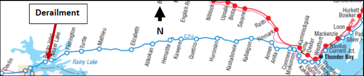
On 10 November 2013, at approximately 1727 Central Standard Time, Canadian National freight train G84042-09, travelling eastward on the Fort Frances Subdivision, derailed 40 loaded grain cars at Mile 73.6, near Nickel Lake, Ontario. There were 2 separate groups of derailed cars, 12 cars in one group and 28 cars in the other. Several of the derailed cars ruptured, spilling grain. There were no injuries.
Factual information
The accident
Eastbound Canadian National (CN) freight train G84042-09 (the train) originated at Melville, Saskatchewan, on 09 November 2013. The train consisted of 184 loaded grain cars. It weighed 24 432 tons and was about 11 058 feet in length. The distributed powerFootnote 1 (DP) train was pulled by 2 head-end locomotives and 1 remote locomotive, which was positioned between the 104th car and the 105th car.
On 10 November at 0956,Footnote 2 the train departed Symington Yards in Winnipeg, Manitoba, en route to Thunder Bay, Ontario. The train was to be operated over the Sprague, Fort Frances, and Kashabowie subdivisions. There was a crew change at Fort Frances, Ontario. The relief crew members, consisting of a locomotive engineer (LE) and a conductor, were rules-qualified. The crew was called at 0900 on Sunday, 10 November, for 1100. They travelled from Neebing (Thunder Bay) to Fort Frances by taxi, arriving at around 1430. They were ordered at 1500 and departed Fort Frances at 1647. The LE had Saturday off and had a good rest Saturday night. The conductor had been off work approximately 24 hours before being called on Sunday morning. The LE had 22 years of experience on the territory and was familiar with operating long, DP trains. This train (G84042-09) was the longest that the LE had operated.
At 1727, the train derailed at Mile 73.6 of the Fort Frances Subdivision, near Nickel Lake, Ontario (Figure 1). At the time of the occurrence, the temperature was −10°C and it was snowing lightly.
Site examination
During the site examination, the following was determined:
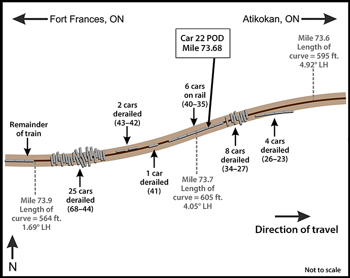
- A total of 40 cars had derailed in 2 blocks (Figure 2).
- The first block involved 12 derailed cars (23rd to 34th cars). The 23rd to the 26th cars had derailed to the south, losing their trucks but remaining upright, straddling the south rail near the beginning of a 4.92° right-hand (RH) curve. The 27th to 33rd cars were jackknifed across the roadbed. The lead set of wheels on the 34th car had derailed.
- About 30 feet west, the next 6 cars, (35th to 40th cars) had remained on the track.
- About 60 feet west, the second block involved 28 derailed cars (41st to 68th cars). The trailing truck of the 41st car had derailed to the south and was straddling the rolled south rail. The next 2 cars, ALNX 396156 and CN 389268, had derailed onto their sides to the north side of the track. The following 25 cars (44th to 68th cars) had jackknifed between a 4.05° left-hand (LH) curve and a 1.69° curve, and were positioned within an area of approximately 10 car lengths.
- There was a broken knuckle between the 41st car and the 42nd car.
- Approximately 1100 feet of track was destroyed.
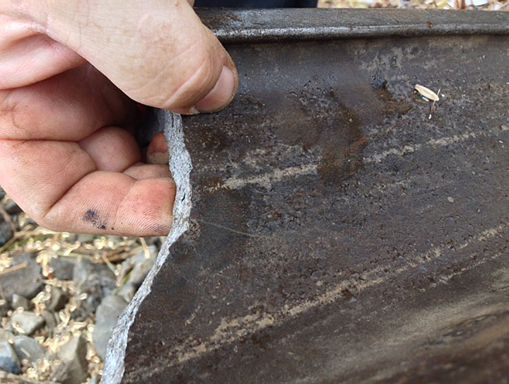
- There were wheel flange marks on the web of the high rail of the 4.05° LH curve (Photo 1).
- There were wheel flange marks on the head of the low rail of the 4.05° LH curve (Photo 2).
- The reported point of derailment (POD) was at Mile 73.68, between the 4.05° LH curve and the 4.92° RH curve, approximately 3 miles west of the Nickel Lake siding.
- The 115-pound high rail, laid in 1991, had 14 mm of head wear and 6 mm of flange wear. CN's track standardsFootnote 3 indicate that the sum of the vertical and flange wear for 115-pound rail shall not exceed 21 mm.
- The 115-pound low rail, laid in 1994, had 13 mm of head wear and no flange wear. CN's track standards indicate that vertical wear for 115-pound rail shall not exceed 16 mm.
- The surface of the rail head exhibited vertical fatigue cracks along the gauge face, longitudinal cracks down the centre, and grinding marks.
- Tie defect countFootnote 4 in the vicinity of the derailment was 15%.
- The nearest rail flange lubricatorFootnote 5 was located at Mile 76.2.
Recorded information
On the day of the occurrence, the train passed 3 hot-box detectors on the Fort Frances Subdivision (i.e., at Mile 120.6, 110.6 and 96.4). Earlier, the train had passed a wheel impact load detector at Sainte-Anne (Mile 127.01 of the Sprague Subdivision). No alarms were encountered at these wayside detectors.
Data from the locomotive event recorder (LER) for the lead locomotive were examined. Based on the LER data and related information, Table 1 provides a summary of events prior to and during the derailment.
| Time | Event |
|---|---|
| 1709:51 | Throttle was increased from position 7 to position 8. Brake-pipe pressure was 90 psi. |
| 1726:48 | Sudden speed change from 37 mph to 36 mph and back to 37 mph in 1 second. |
| 1726:49 | Undesired emergency brake application (UDE) was triggered. |
| 1726:52 | Loss of air on lead locomotive. Train speed was 37 mph.Footnote 6 There was a 0.5 to 1.4 mph/s deceleration. |
| 1726:52–1727:00 | Cars 23 to 26 were pulled to the south side of the track on the tangent track approaching the 4.92° RH curve. The train separated between cars 22 and 23. Cars 27 to 34 derailed and piled up on the 4.05° LH curve. |
| 1727:00 | UDE arrived at the end of train (EOT) (i.e., the sense and braking unit [SBU]). The entire train was in emergency braking. |
| Starting from about 1727:00 | Cars 42 and 43 buckled out of the train line. Car 41, in turn, derailed and separated from cars 40 and 42. Cars 44 to 68 continued rushing forward, derailed and jackknifed across the grade. |
| 1727:02 | Throttle was reduced to position 7. |
| 1727:13 | Throttle was reduced to position 4. |
| 1727:14 | Throttle was reduced to high idle. |
| 1727:46 | About 54 seconds after the loss of air, the head end of the train (i.e., the locomotives and the first 22 cars) stopped after travelling about 1800 feet. |
The lead locomotive, an EMD SD70M-2, was equipped with a pneumatic control switch, which delays the power knock-down by 20 seconds during a train-line–initiated emergency. In this occurrence, throttle-8 power had remained applied for 10 seconds after the train went into emergency and before the LE started to reduce the throttle. The throttle was progressively reduced to position 4 over the next 11 seconds when power was cut after the 20-second pneumatic control switch delay timed out. The head-end locomotives and the remote locomotive received the emergency signal at about the same time (i.e., at 1726:52). Approximately 8 seconds later, the EOT (i.e., SBU) initiated an emergency from the tail end after recognizing the drop in brake-pipe pressure.
Follow-up testing determined that the automatic radio emergency command (initiated at the head of the train) did not reach the EOT (SBU) due to an interruption in Train Information and Braking System (TIBS)Footnote 7 communications.Footnote 8
Wheel-slip alarms had sounded throughout the trip. This alarm occurs when a wheel in the locomotive consist is slipping (i.e., due to lack of adhesion). In most situations, wheel slip can be detected and corrected automatically. The automatic wheel-slip detection system on the locomotive will reduce the power to the traction motors and will apply sand to the rails until the wheel(s) stop slipping.Footnote 9 Automatic sanding had been on and was occurring intermittently throughout the trip.
At the time of the emergency braking, the train brakes and the independent locomotive brake both activated. The locomotive brakes were not bailed off (i.e., released). CN's Locomotive Engineer Operating Manual, Form 8960, Section G 2.8, requires the independent or locomotive brakes to be released when the head end of the train is stretched to avoid a run-in, and actuated or applied when the head end of the train is bunched to prevent the head end from running out as the train slows.
Train G84042-09
Before the derailment, the train was being operated in a stretched condition over relatively flat terrain. It was being operated in DP synchronous mode and had a horsepower/ton (HPT) ratio of 0.5. The HPT ratio is based on train service design to ensure that the minimum number of locomotives is used to power the train. The HPT ratio is determined by dividing the total available horsepower of the operating units by the tonnage of the train.Footnote 10
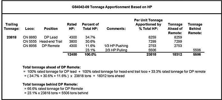
To configure a DP train, some Class 1 railways use the “push ½ and pull ½” rule of thumb. In contrast, CN's DP placement guideline calls for the remote locomotive to be placed in the train such that it pushes 1/3 of its tonnage rating (not entire train tonnage) and pulls 2/3.
For the occurrence train, the calculated tonnage to be placed in front of the DP remote (Appendix A) includes
- 100% of the rated tonnage for the lead locomotive (34.7% based on total horsepower [HP]);
- 100% of the rated tonnage for the head-end trail locomotive (30.6% based on total HP in this case); and
- 33.3% of the rated tonnage for each locomotive in the DP remote consist (11.6% based on total HP in this case).
For the occurrence train, the remote locomotive was acting as 1 of 3 contributing locomotives. Given that the total tonnage for the train needed to be suitably apportioned across all 3 locomotives:
- The position of the remote locomotive took into consideration the switching plan at Thunder Bay terminal. Since 1 long train cannot fit into any 1 inbound track, splitting the train at the DP creates 2 trains that can be accommodated at the terminal.
- The calculation using tonnage ratings of the head-end and remote locomotives determined that the optimal tonnage ahead of the remote locomotive was 18 312 tons and 5506 tons behind the remote locomotive.
However, train G84042-09 was marshalled with 12 828 tons ahead of and 10 990 tons behind the remote locomotive. Based on CN's DP placement guideline, the remote locomotive was positioned too far ahead. CN's guideline also includes a latitude factor of +/-25%. Given the latitude factor, the minimum tonnage ahead would have been 16 936 tons and the maximum tonnage behind would have been 6883 tons. The occurrence train had been configured with 4108 tons more behind the remote locomotive than the guideline stipulated.
Distributed power train operations on the Fort Frances Subdivision
CN risk assessments were conducted in 2011 and 2012 on DP train operations for 224-car coal trains between Bickerdike, Alberta, and Prince Rupert, British Columbia. The risk level was rated low. CN engineering confirmed that bridges and infrastructure were adequate for the intended operation. CN main lines, including the Winnipeg-to-Thunder Bay route, are all rated for 286 000-pound loading. The risk assessment stated that “expansion to other routes will require a review of specific and/or additional hazards to be addressed through a separate risk assessment applicable to that route.” CN advised that the assessment was also applicable to the Winnipeg-to-Thunder Bay route.
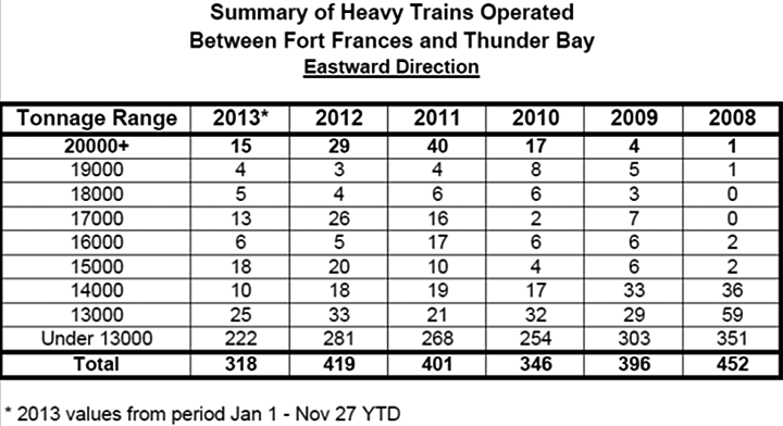
Compared with long, conventional trains, DP trains increase operational safety by reducing in-train forces, rolling friction, rail wear in curves, and the risk of rail rollover. Table 2 provides a summary of heavy train operations on the Fort Frances Subdivision for the 6-year period from 2008 to 2013.
At the time of the occurrence, CN had been moving as much grain as possible from Prairie grain terminals to Thunder Bay before winter; 2013 had been a record crop year for grain.
Long DP trains had been operating over the Fort Frances Subdivision for several years prior to this occurrence. Operation of this type of train often required forward planning by the LE to avoid excessive in-train forces. Forward planning involved knowing the terrain and being aware of the total HP, of the tonnage of the train, and of where the empty cars and loaded cars were positioned in the train.
While en route, situational awareness was also important as the LE had to be aware of
- where the trailing portion of the train was located on the terrain;
- where the DP was located; and
- what restrictions, if any, were coming up (e.g., signal indication, slow orders, and work limits).
With the forward-planning information, the LE determines what actions to take to control the speed of the train in a given situation. CN's train handling guidelines (CN Form 8960) are designed to help keep in-train forces to a minimum.
During the week before the occurrence, 3 similar DP trains had travelled eastward between Fort Frances and Thunder Bay:
- On 04 November, train G84041-04 consisted of 145 loaded grain cars and weighed 19 446 tons.
- On 08 November, train G84042-08 consisted of 195 loaded grain cars and weighed 25 751 tons.
- On 09 November, train C77251-06 consisted of 151 loaded grain cars and weighed 20 979 tons.
A review of the LER data for these trains determined that
- All 3 trains had been operated at a speed that was slightly higher than permitted (i.e., up to 35 mph) through the derailment area; and
- The train crews had been using throttle manipulation to moderate speed in order to comply with the 30-mph permanent slow order.
For eastward trains approaching the derailment location, the terrain can be categorized as having a mild descending grade with tight reversing curves and some short sections of tangent track. Near the POD, Mile 73.6, the track gradient transitions into a mild ascending grade (0.2% to 0.3%) for the next mile with tight reversing curves, followed by 1 mile of moderate descending grade, transitioning into a steeper climb (0.6%) from about Mile 71.7 to the crest at Mile 71. Due to these physical characteristics, eastward trains proceeding beyond the POD can expect the tight curvature and ascending grades to have a retarding effect on their progress.
Equipment information – CN 388054
The 22nd car, CN 388054, was a covered hopper car with a 286 000-pound capacity and was built in September 1995. CN mechanical records indicate that
- The A-end Barber S2-HD truck had been fully reconditioned and placed under the car in November 2006;
- The number 4 wheel set had been equipped with new CJ-36 wheels and reconditioned roller bearings in November 2012; and
- The number 4 wheel set had been placed under CN 388054 in January 2013.
Examination of CN 388054 at the accident site determined the following:
- The trailing truck on this car was the first to derail.
- The high rail of the 4.05° LH curve had likely rolled out or broken, allowing the trailing L-4 wheel to drop down and ride on the web and base of the high rail, spreading the high rail behind it as it proceeded. The L-4 wheel then re-railed itself, as CN 388054 was found with all wheels on the rail.
On 11 December 2013, a teardown inspection of the A-end truck was conducted at CN Symington Shop in Winnipeg. The following was determined
- The A-end truck was in like-new condition with little to no wear in the constant contact side bearings, side wedges, bolster gibs, and bolster bowl.
- There was no indication that the truck had been binding or skewing.
- The wheels had a good tread profile.
- Impact marks were present on the L-4 wheel flange and tread (Photo 3). The marks were consistent with the wheel impacting a broken rail and/or rail anchors.
- On the L-4 wheel, there was abrasion throughout the rim face circumference and flange (Photo 4).


Track information
In the vicinity of the derailment, the track had a permanent slow order (between Mile 73.1 and Mile 79.7) where the maximum freight train speed was 30 mph. On the Fort Frances Subdivision, there were five 30-mph permanent slow orders, which had been placed due to curvature and undulating grades. At these locations, the track was Class 3 track. The annual tonnage over the Fort Frances Subdivision was about 11 million gross tons.
At the derailment site, there were 2 reversing curves separated by 182 feet: a 4.05° LH curve and a 4.92° RH curve. The high rail in the 4.05° LH curve was 1989/1991 115-pound Sydney continuous welded rail, and the low rail was 1994 115-pound Sydney and Algoma continuous welded rail. The rails were laid on 14-inch tie plates, spiked on wood ties, and anchored every tie. The ballast was crushed rock in good condition.
The 4.05° LH curve was situated in an area where level track began to ascend at a 0.3% grade. This curve was 605 feet long, and the average superelevation was 0.35 inch.
Track inspection and maintenance
In the vicinity of the derailment, Transport Canada had conducted an inspection on 25 April 2012. No track defects were noted.
During the most recent track geometry inspection (09 July 2013), it was determined that
- Within the 4.05° LH curve, there was 117 feet of wide gauge over ½ inch, 136 feet of wide gauge over ¾ inch, and 23 feet of wide gauge over 1 inch;
- Within the 4.92° RH curve, there was 175 feet of wide gauge over ½ inch, 41 feet of wide gauge over ¾ inch, and 10 feet of wide gauge over 1 inch; and
- Within the 2 curves, there were minor, non-actionable high-rail cantFootnote 11 anomalies.
As specified in the Transport Canada–approved Track Safety Rules, the maximum gauge for Class 3 track is 57¾ inches (i.e., 1¼ inches wide).
To correct the wide gauge defects in the curves, 260 feet of track had been re-gauged on 06 September 2013. The re-gauging work involved removing high-rail gauge spikes, pulling the high rail down into gauge, hand-adzing new seats for the tie plates, filling spike holes with glue, and fully spiking all 6 holes in the tie plates. Hand-adzing ties is common, but not as exact as that done by machine and may result in uneven or excessive rail cant. The minor, non-actionable high-rail cant anomalies, which were identified during the 09 July track geometry inspection, would have been corrected by the gauging work. No additional track geometry inspection had been conducted between 06 September and 10 November to verify the effectiveness of the gauging.
On 11 October 2013, a rail flaw detection test had been conducted. No rail defects were detected in the area of the derailment. Between 2010 and 2013, rail flaw detection through the derailment area had been conducted 15 times. For the 3 tests conducted in 2013 (i.e., 21 March, 12 June and 11 October), 6 defects were detected, but none between Mile 73 and Mile 74. Most of the rail defects detected on the Fort Frances Subdivision involved crushed heads in the older tangent rail, bolt-hole cracks in jointed rails, and defective welds.
On 05 November 2013, the track had been visually inspected by hi-rail. No defects were observed in the derailment area.
Rail grindingFootnote 12 had been conducted on the Fort Frances Subdivision in early May 2013 before the gauging work was performed.
A Transportation Technology Center, Inc./Norfolk Southern report (TD-11-052, Root Cause of Rail Roll/Reverse Rail Cant) determined that certain track maintenance tasks (e.g., gauging, rail cant restoration and tie renewal) can result in track conditions that are susceptible to high lateral forces, reducing the track structure's ability to resist gauge-widening forces. In curves, these track maintenance activities tend to move the contact position of the wheel towards the field side of the high rail and towards the gauge side of the low rail. The high rail will tend to have strong 2-point contact, resulting in poor curving performance. Vertical load applied to the field side of rail, due to poor wheel/rail profile contact, results in low rail base/rail height (B/H) ratiosFootnote 13 (Figure 3) and a high risk of rail rolloverFootnote 14 unless the rail profile is corrected by rail grinding.

Curve superelevation
As a train negotiates a curve, it is desirable for the vehicles (i.e., locomotives, cars) to tilt inward towards the centre of the curve. This can be achieved by elevating the outer rail. If all trains were to operate at the same speed through the curve, the ideal condition for smooth riding and for minimum rail wear would be to elevate the high rail such that, at that speed, the centrifugal force on the high rail (outer) and the low rail (inner) are equal (i.e., equilibrium speed). This is known as “balanced superelevation.”
However, there will normally be different types of traffic at different speeds. In curves, trains travelling slower than the equilibrium speed will result in higher-than-normal wear on the low rail. Conversely, trains travelling faster than the equilibrium speed will result in higher-than-normal wear on the high rail. The mix of traffic and train performance on a rail line are elements to consider when determining the superelevation of the curve.
The CN standard for curve superelevation is RM-1305, which specifies (in part) the following:
- The maximum superelevation that can be applied on a curve has to be the balanced superelevation or 5 inches, whichever is less.
- The minimum superelevation that can be applied on a curve shall be the greater of ½ inch, 2 inches below the balanced elevation for freight timetable speed, 3 inches below the balanced elevation for passenger timetable speed, or 6 inches below the balanced elevation for LRC (Light Rapid Commuter) timetable speed. The elevation can be anywhere within this range.
In this occurrence, the 4.05° LH curve was 605 feet long with average superelevation of 0.35 inch. Based on CN standards
- The minimum superelevation for 30 mph on a 4.05° curve would be the balanced superelevation of 2.5 inches less 2 inches or 0.5 inch. With an actual superelevation of 0.35 inch, the equilibrium speedFootnote 15 was 11 mph. At 0.35-inch actual superelevation and 2 inches superelevation imbalance, the design speed was 28.8 mph, which is just less than the speed for the permanent slow order (i.e., 30 mph).
- For a speed of 37 mph, the balanced superelevation of a 4.05° curve is 3.9 inches. To operate at this speed, the minimum superelevation on the curve would have been the greater of 0.5 inch, or 3.9 inches less 2 inches or 1.9 inches).
Lateral and vertical forces at the wheel/rail contact
A combination of lateral (L) and vertical (V) forces exist at the wheel/rail contact (Figure 4). The ratio of lateral-to-vertical (L/V) forces provides an indication of the likelihood of a derailment. The probability of a derailment increases as the L/V ratio increases. A high lateral force, combined with a low vertical force (e.g., empty cars), will tend to push the wheel flange up and over the gauge face of the rail (i.e., wheel climb), or push the rail outward with sufficient force to cant the rail outward and roll over the rail.

The traditional L/V threshold for wheel climb (empty car) is 0.82. For rail rollover (loaded car), the L/V threshold is 0.65. If the resultant force acts beyond the outer edge of the rail base, wheel climb or rail rollover may occur.
In curves, the following situations will affect the lateral and vertical forces:
- When there is wear on the gauge face of the high rail, 2-point contact between the wheel and the rail may occur when flanging around the curve, lowering the L/V threshold for wheel climb or rail rollover.
- The wheel flanges, centrifugal forces and frictional curving forces of wheel truck assemblies will exert lateral force on the high rail. In-train forces (i.e., buff and draft forces) can also exert lateral force on the track.
- As lateral forces try to tip the rail over, the rail is restrained by its torsional stiffness and by the weight on adjacent wheels.
- Raising the high rail (i.e., superelevation) compensates for centrifugal force by shifting some car weight to the low rail, reducing the lateral force (centrifugal) and the vertical force on the high rail.
- Lubricating the gauge side of the low rail will reduce frictional curving forces that may cause high rail rollover or low rail wheel drop-in.
- For a wheel to drop in, there must be either a significant increase in lateral load on the track or a significant reduction in lateral strength of the track.
Train dynamic analysis
CN analyzed the emergency brake propagation and had a third-party simulation analysis conducted for the train travelling through the 4.05° LH curve. Track geometry data from the 09 July track geometry inspectionFootnote 16 were used. Other input included train marshalling, speed, train handling information, and a moderately worn rail profile. The following was determined:
- Just before the derailment, there was minimal slack action and low-level in-train forces. This was the expected result given that the train had been travelling over relatively flat terrain in throttle 8 in a steady-state and stretched condition. The grades and curves in the area were not known to be problematic for train handling.
- The tail end of the train went into emergency braking about 8 seconds after the head end of the train due to a front-to-rear TIBS communication interruption. The EOT emergency was initiated in response to the drop in brake-pipe pressure at the last car (i.e., going to 0 psi), rather than in response to the head-of-train input and display unitFootnote 17 receiving an emergency radio command.
- Air propagation calculations indicate that the UDE had initiated in the vicinity of the 22nd and 23rd cars.
The in-train forces leading up to the derailment were also analyzed. For this analysis, the rail was assumed to be new and dry and the wheel profiles to be half-worn, new profiles. The following was determined:
- Longitudinal forces on the derailed cars were 70 000 pounds at the time of the derailment. This force level was considered low and not causal.
- No slack (buff) action occurred anywhere in the train at the time of the derailment.
- Calculated L/V wheel ratioFootnote 18 was below 0.35 while the cars were traversing the point of derailment.
- Maximum lateral wheel forces did not exceed 15 000 pounds. This level of lateral forces is considered moderate and sustainable by well-maintained track.
The effect (if any) of the broken knuckle between the 41st and 42nd cars on the derailment was analyzed. It was determined that
- The onset of high force levels started about 20 seconds after the UDE was initiated, making it unlikely that the UDE event preceded the derailment; and
- Given the additional distance travelled during the 20-second interval and the low level of in-train forces prior to the derailment, the broken knuckle likely did not occur before the derailment, but occurred due to excessive forces during the derailment sequence.
Another train dynamic analysis was conducted to assess the L/V forces for the train travelling through the 4.92° RH curve. This analysis was also based on the 09 July track geometry information along with a severely worn-curve high-rail profile and the wheel profiles of the trailing wheels of the 22nd car. The following was determined:
- L/V derailment conditions were not present. Although the wheel L/V ratio of 0.43 exceeded that of the previous simulation (<0.35), the maximum truck-side L/VFootnote 19 was 0.21, which was less than the B/H ratio of 0.32, indicating a low potential for rail rollover.
- The maximum lateral wheel force (i.e., considered moderate and sustainable by well-maintained track) was calculated to be 16 400 pounds and was not significantly higher than the previous analysis.
These results were applicable for both the 4.92° RH curve and the 4.05° LH curve.
TSB Laboratory examination
Two pieces of broken rail and part of a coupler assembly (between the 41st and 42nd cars) were recovered and sent to the TSB Laboratory for examination and analysis.
Examination of the broken rail determined the following:
- All rail fractures were due to overstress.
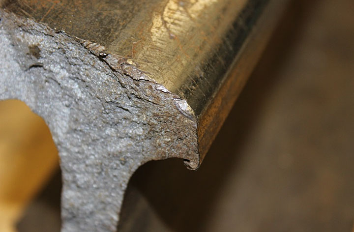
- There was a small fatigue crack on the gauge side of the larger piece of rail (Photo 5). This crack was about 7 mm wide by 3 mm deep.
- The small fatigue crack was likely associated with the light shelling on the rail-head gauge side. This small fatigue crack had acted as the initiation site for the overstress failure.
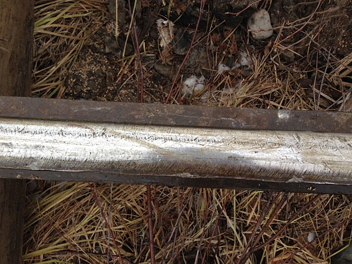
- The rail head had ½-inch vertical wear and ¼-inch flange wear.
- On the smaller piece of rail (Photo 6), which was from the high rail of the curve, there were signs of batter and wheel strike marks.

Examination of the coupler assembly determined that the coupler fractures were due to overstress.
Keeping and preservation of evidence
This derailment occurred in a relatively remote location. By the time TSB investigators arrived on site (approximately 22 hours after the occurrence), track restoration work by the railway had already started. It is recognized that the railway will want to restore service as soon as possible and that derailment wreckage must often be moved to accomplish that. In addition, for safety reasons, there may be a need to move some of the derailment wreckage to minimize further damage (e.g., during fires). If possible, before the accident site is disturbed, the position of the wreckage should be recorded and documented. This information and relevant salvaged evidence must then be preserved for the follow-up investigation.
Transportation Safety Board Regulations (the Regulations) set out the requirements for keeping and preserving evidence. The Regulations in effect at the time of the accident stated:
9. (1) Subject to subsections (2) and (3), where a reportable accident or incident takes place, the owner, operator, master and any crew member shall, to the extent possible, and until otherwise instructed by the Board or except as otherwise required by law, preserve and protect any evidence relevant to the reportable accident or incident, including evidence contained in documents as defined in subsection 19(16) of the Act.
(2) Subsection (1) shall not be construed as preventing any person from taking necessary measures to ensure the safety of any person, property or the environment.
(3) Where evidence relevant to a reportable accident or incident has to be interfered with pursuant to subsection (2), the person directing, supervising or arranging the interference shall, to the extent possible in the circumstances, and prior to the interference, record the evidence by the best means available.
(4) Where any person required to do so pursuant to subsection (1) preserves and protects evidence relevant to a reportable accident or incident, no other person referred to in that subsection is required to preserve or protect that evidence.
Analysis
There was no indication that a mechanical failure on any of the rolling stock contributed to the accident. The analysis will focus on train dynamics, distributed power (DP) long-train operation, track conditions, and rail conditions.
The accident
Despite extensive review of the collected information, a clear cause for the derailment was not identified. The point of derailment (POD) was in the area of a 4.05° left-hand (LH) and a 4.92° right-hand (RH) curve. The reason for the undesired emergency brake application was not determined. The train dynamics analysis identified lateral-to-vertical (L/V) ratios that were not sufficiently large for a rail rollover or wheel-climb derailment. The longitudinal forces and lateral forces were considered low to moderate. Inspection of the trailing truck of the 22nd car revealed no abnormal conditions that may have led to the derailment.
Many unit trains operate over the Fort Frances Subdivision. A unit train consist is usually uniform (i.e., all cars are of the same design and loading). Each rail car on a unit train will normally respond to track irregularities in the same manner as the previous car, thereby concentrating the cumulative impacts at locations of track irregularities. Long unit trains with high load capacity provide the track little or no opportunity for elastic recoveryFootnote 20 during their passage. As a result, loaded high-capacity rail cars in unit trains can accelerate the degradation of the track structure.
The derailment likely initiated when the high rail of the 4.05° LH curve rolled out, allowing the trailing L-4 wheel of the 22nd car (CN 388054) to drop down and ride on the web and base of the high rail, spreading the high rail behind it as it proceeded. The L-4 wheel then re-railed itself as CN 388054 was found with all wheels on the rail. There were 2 blocks of derailed cars separated by 6 non-derailed cars. The last 25 cars to derail were jackknifed across the roadbed, suggesting a run-in after the initial derailment and separation of the lead cars. Due to the 8-second delay in activation of the end of train braking, the tail end of the train continued to move forward after the head-end portion of the train and the remote locomotive began to brake, resulting in the jackknifing of the second group of cars.
The effects of train dynamics, DP long-train operation, track conditions, and rail conditions were analyzed. The following was determined:
- The 4.05° LH curve was elevated for a speed of 28.8 mph. With the train operating at 37 mph, which was 7 mph over the posted speed limit of 30 mph, the curve was under-elevated for this speed. This resulted in more lateral forces being exerted on the high rail. While these forces were considered moderate and sustainable by well-maintained track, they were not sustainable for the worn-curve high rail.
- With the increase in the number of long, heavy trains operating over the subdivision (since 2010), and with some trains operating at speeds that are slightly higher than permitted, higher lateral forces would have been exerted on the high rail of the under-elevated 4.05° LH curve. In addition, the rate of wear on the high rail would have increased. The high rail had 14 mm of head wear and 6 mm of flange wear, which was just within Canadian National's (CN) allowable track standard (i.e., the sum of the vertical and flange wear for 115-pound rail shall not exceed 21 mm). For a high rail that was reaching its wear limits, 2-point contact at the wheel/rail interface likely occurred, resulting in a lower L/V derailment threshold.
- The curve had been re-gauged about 2 months before the derailment. However, the heavy loaded unit trains would have accelerated the degradation of the spike fasteners' ability to resist lateral-force gauge widening and rail rollover.
- Each of these factors on its own would not likely have resulted in the derailment. However, when acting in combination, these factors may have been sufficient to create the necessary derailment conditions. The derailment likely occurred due to a high lateral-force rail rollover from a combination of train speed on the under-elevated curve, lowered L/V threshold due to 2-point contact on the worn high rail, and degraded rail fastener resistance to dynamic wide gauge.
Effect of rail cant restoration and gauging on the wheel/rail interface
Rail cant restoration and gauging tend to move the contact position towards the field side of high and low rails if the rail profile is not corrected by rail grinding. In this occurrence, rail grinding of the curves was done before the rail cant restoration and gauging, and not after these maintenance activities. If rail grinding is not performed following rail cant restoration and gauging, 2-point contact at the wheel/rail interface can occur, resulting in higher lateral forces and increasing the risk of rail rollover.
Train handling and braking during the derailment
In this occurrence, the second group of derailed cars comprised 25 cars that were jackknifed across the grade. Prior to the derailment, there was minimal slack action as the train had been travelling over relatively flat terrain in a stretched condition. There had been no brake application prior to the emergency that would have resulted in excessive buff forces. However, due to a front-to-rear Train Information Braking System communications interruption, there was an 8-second delay for the tail end of the train to initiate emergency braking. When the train is stretched, to prevent wheel slide or excessive in-train buff forces from the cars rapidly bunching up behind the locomotive, the locomotive brakes could be bailed off (i.e., released), which did not occur. The delay in braking from the tail end of the train and the fact that the locomotive brakes were not bailed off allowed the braking cars to bunch up, creating a jackknifing situation that increased the severity of the derailment.
Distributed power long-train operation
CN's DP placement guideline indicates that a remote locomotive should be placed in the train such that it pushes 1/3 of its tonnage rating and pulls 2/3. For the occurrence train, the optimal tonnage ahead of the remote locomotive was 18 312 tons, and the optimal tonnage behind the remote locomotive was 5506 tons. Based on CN guidelines, train G84042-09 was marshalled with the remote locomotive positioned too far ahead.
The benefits of a DP train include the minimization of in-train forces during train operations and the quicker application of air brakes throughout the train when braking. The full benefits of operating the occurrence train were not realized by placing the remote locomotive too far forward in the train. However, the placement of the DP remote locomotive, while not in accordance with CN guidelines, did not contribute to the derailment.
Preservation of evidence for investigations
Many derailments occur in isolated locations that are difficult to access. Local railway personnel will normally arrive on site shortly after the occurrence. In comparison, it can take a considerable amount of time for Transportation Safety Board of Canada (TSB) investigators to arrive. In this occurrence, the derailment site was in a remote location. By the time TSB investigators arrived on scene, restoration work was already under way.
It is recognized that the railway will want to restore service as soon as possible and that wreckage must be moved to accomplish that. However, prior to disturbing the derailment site, the position of the wreckage and its movement should be recorded and documented. Transportation Safety Board Regulations indicate that every person with possession of or control over evidence relating to a transportation occurrence must keep and preserve the evidence unless the Board provides otherwise. Then, once TSB investigators arrive on scene, the salvaged evidence would be available for the investigation.
CN personnel will normally make efforts to locate the POD and determine the cause of the derailment, including locating broken rails of interest. In this occurrence, only 2 pieces of rail were recovered, neither of which proved conclusive. Due to CN's track restoration activities, the TSB was not able to examine the undisturbed derailment site, including key portions of the track, to verify the cause of the derailment. This situation had been encountered in a previous TSB investigation (TSB Railway Investigation Report R09W0033). When evidence from occurrence sites is not preserved, the TSB may be hindered in determining the causes and contributing factors, and in identifying safety deficiencies in the transportation system.
Findings
Findings as to causes and contributing factors
- The derailment likely initiated when the high rail of the 4.05° left-hand curve rolled out, allowing the trailing L-4 wheel of the 22nd car (CN 388054) to drop down and ride on the web and base of the high rail, spreading the high rail behind it as it proceeded.
- With the train operating at 37 mph, the curve was under-elevated for this speed, resulting in more lateral forces being exerted on the high rail.
- With the high rail that was reaching its wear limits, 2-point contact at the wheel/rail interface likely occurred, resulting in a lower lateral-to-vertical derailment threshold.
- Heavy loaded unit trains, operating at or slightly over permitted speed, would have accelerated the degradation of the spike fasteners' ability to resist lateral-force gauge widening and rail rollover.
- The high lateral-force rail rollover likely occurred from a combination of train speed on the under-elevated curve, lowered lateral-to-vertical threshold due to 2-point contact on the worn high rail, and degraded rail fastener resistance to dynamic wide gauge.
Findings as to risk
- If rail grinding is not performed following rail cant restoration and gauging, 2-point contact at the wheel/rail interface can occur, resulting in higher lateral forces and increasing the risk of rail rollover.
Other findings
- The delay in braking from the tail end of the train and the fact that the locomotive brakes were not bailed off allowed the braking cars to bunch up, creating a jackknifing situation that increased the severity of the derailment.
- The placement of the distributed power remote locomotive, while not in accordance with Canadian National guidelines, did not contribute to the derailment.
- When evidence from occurrence sites is not preserved, the Transportation Safety Board of Canada may be hindered in determining the causes and contributing factors, and in identifying safety deficiencies in the transportation system.
This report concludes the Transportation Safety Board’s investigation into this occurrence. the Board authorized the release of this report on . It was officially released on 03 March 2015.
Appendices
Appendix A - G84042-09 horsepower and tonnage calculation